

Page 1

PRO 4 MINI
MULTI CHANNEL WIRELESS SYSTEM
WITH CDM4 DISTRIBUTION MODULE
OPERATING INSTRUCTIONS
and trouble-shooting guide
LECTROSONICS, INC.
Rio Rancho, NM
Page 2

INTRODUCTION
The PRO 4 mini system is a high quality wireless microphone system designed primarily for motion picture and
television production - both in the studio and in the field. The design features included are the direct result of
suggestions garnered during many conversations with industry engineers, cameramen, and audio producers.
These suggestions, together with meticulous attention to design and construction details, have resulted in a system
that offers portability, versatility, and "bullet-proof" reliability of operation.
The PRO 4 mini system consists of a CDM4 RF/power distribution module and a rechargeable battery pack
installed in a compact machined aluminum housing. The PRO 4 mini system is available with up to four CR185
wireless receivers and companion transmitters, or by itself to combine existing CR185 receivers. The system
comes in a padded, reinforced naugahyde carrying case. Zippered front and rear panels provide easy access to
controls and connectors.
Problems such as interaction of receivers, intermodulation and desensitization, etc. have been eliminated through
creative engineering and superior design. The integral CDM4 distribution modules provides convenience of
operation from a single antenna and power supply without degrading the performance of the CR185 receivers. In
fact, the additional RF filtering in the CDM4 module actually improves the already outstanding selectivity of the
CR185 receivers.
The PRO 4 mini makes portable multi-channel wireless simple and trouble-free.
TABLE OF CONTENTS
INTRODUCTION .......................................... 2
GENERAL TECHNICAL DESCRIPTION .......................... 2
FRONT PANEL DESCRIPTION ................................ 3
REAR PANEL DESCRIPTION ................................. 4
INSTALLATION ........................................... 5
OPERATING INSTRUCTIONS ................................. 5
TROUBLESHOOTING ....................................... 6
SPECIFICATIONS ......................................... 7
SERVICE AND REPAIR ..................................... 8
RETURNING UNITS FOR REPAIR ............................. 8
WARRANTY ....................................... Back cover
1
Page 3
GENERAL TECHNICAL DESCRIPTION
The PRO 4 mini consists of two sub-systems; the housing which contains the gel-cell power supply and the
modules, and the CDM4 RF/power distribution module.
The housing is built of machined aluminum and covered with a vinyl carrying case. The handle is bolted directly to
the top aluminum panel of the case for security. The 6V, 4.8 Ah Panasonic LCR-456-P lead-acid gel-cell batteries
are connected in series to provide 12 Vdc power to all the modules installed into the system. These batteries were
selected for their recharge characteristics and reliability under extreme conditions.
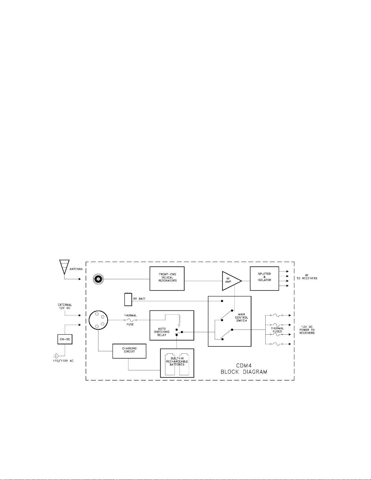
The CDM4 RF/power distribution module is the heart of the PRO 4 mini system. Helical resonators in the front end
of the RF section attenuate out-of-band RF signals preventing intermodulation and front end overload. Following
the resonators is a low noise, low gain RF amplifier designed to evenly compensate for splitter losses in the stage
that follows. A precision splitter/isolator divides the RF signal into four isolated signals preventing spurious RF
coupling between receivers. The splitter/isolator is termination independent which prevents mismatched or
disconnected RF outputs from affecting the other receivers.
Power can be supplied to the CDM4 module from four possible sources. The primary source is the gel-cell battery
pack built into the bottom of the housing. Power may also be provided through an external DC power source of 12
to 20 Vdc of either polarity. When an external source is connected, an internal relay automatically disconnects the
internal battery pack. If that DC source fails or is disconnected, the system automatically reverts to the internal
batteries. AC power can be provided through the CH-50 charger included with the unit. While operating in the AC
mode, the internal batteries are also recharged. The individual receivers and the CDM4 module can also be
operated from internal 9V alkaline batteries housed inside each unit’s battery compartment. In this mode of
operation, all receivers and the CDM4 have to be manually switched for "internal" power. All power circuits are
protected by internal auto-reset fuses in the CDM4. Should the power to one receiver fail, the others will continue
to operate.
Figure 1 - PRO 4 mini Block Diagram
2
Page 4

FRONT PANEL DESCRIPTION
ANTENNA LEADS - These BNC terminated leads provide isolated RF signals for each receiver installed in the
system.
ANTENNA - The helical antenna provided with the unit attaches to this BNC connector directly with a twist lock
motion. Other 50 Ohm antennas designed for the VHF high band may also be used.
POWER SWITCH - The power switch has three positions. The OFF position turns off power to all modules in the
system. The MAIN/EXT position activates the system and draws power from the gel-cell batteries located in the
bottom of the system or from an external 12 Vdc power source. This power is distributed to all receivers installed
in the system. The INT 9V position activates the CDM4 module only, drawing power from the CDM4’s internal 9v
battery.
EXT LED - This LED will light when power is provided from an external 12 Vdc power supply.
12V LED - This LED indicates operation from the internal gel-cell batteries.
CHARGING LED - This LED lights when the gel-cell batteries are being charged with the CH-50 charger. It will
extinguish when the batteries achieve full charge.
AC LED - This LED indicates the unit is plugged into AC with the CH-50 charger. It remains on as long as the
charger is connected, regardless of the battery charge state.
INSTALLATION SCREWS - These screws are used for receiver installation and removable. See page 5 for further
instructions.
Figure 2 - PRO 4 mini Front Panel
3
Page 5
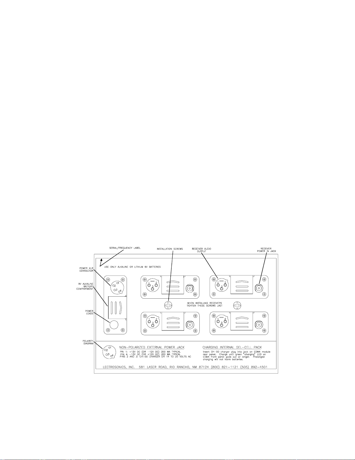
REAR PANEL DESCRIPTION
SERIAL/FREQUENCY LABEL - This label indicates the serial number of the CDM4 module. It also indicates the
RF pass-band of the unit. IMPORTANT - The CR185 receivers installed in the unit must fall between the
frequencies indicated on the label. Serious signal loss results if the receivers are outside the RF passband.
POWER XLR CONNECTOR - This 4 pin Switchcraft D4M connector is the power input jack for both the CH-50 AC
charger and for external 12V power. Pins 1 and 4 are used for 12 Vdc input. Pins 2 and 3 are utilized for 14 to 20
Vac charging voltage.
POLARITY DIAGRAM - The polarity diagram on the lower panel indicates the wiring connections for the 4 pin XLR
power connector. Use this diagram when connecting your own external power source to the system.
9V ALKALINE BATTERY COMPARTMENT - The CDM4 module can operate from an internal 9V alkaline battery.
Only alkaline or lithium batteries are recommended. Poor results may be expected with other battery types. This
compartment opens by pressing in and to the right. The compartment will adjust to various battery sizes.
POWER LEADS - These connectors provide power for the individual receivers. Insert the connectors into the jack
provided on each receiver.
INSTALLATION SCREWS - The two large counter-sunk phillips head screws in the central area between the
receivers are used for receiver installation and removable. See page 5 for further instructions.
RECEIVER AUDIO OUTPUT - Supplies a balanced, low impedance output at microphone level. The audio signal
is output on pins 2 and 3, while pin 1 is ground. The output level of this jack is controlled by the OUTPUT control
on the front panel of the receiver. The connector is a standard XLR type.
RECEIVER POWER IN JACK - Connects to the POWER LEAD for powering the receiver from the PRO 4 mini
source. A diode bridge is used in the external power input, so that the CR185 will operate properly from either
polarity.
Figure 3 - PRO 4 mini Rear Panel
4
Page 6

INSTALLATION
The CDM4 RF/power distribution module is permanently installed into the housing assembly and should never need
to be removed except in the rare case of repair. Removal of the CDM4 module requires case disassembly and is
not recommended.
The PRO4 mini is designed to contain up to four CR185 receivers. Installation of these receivers is quite simple.
First, loosen but do not remove the two large counter-sunk phillips head screws in the front and two in the rear
panels of the housing. These screws are located in the horizonal center band of metal between the receivers.
(See Figures 2 and 3) Insert the CR185 receivers, front end first (the end with the antenna connection), in through
the rear panel. Seat the front end of the receiver into the recessed lip of the PRO4 mini front panel. Make certain
the antenna cables are positioned properly through the slot to the right of each opening. The rear panel of the
receiver will extend the same amount as the rear panel of the CDM4 module when the unit is properly seated.
Repeat this for each receiver to be installed. After each receiver is in place, tighten the front panel screws first.
These screws should be fairly snug but excessive force should be avoided and is unnecessary. You are
compressing a natural rubber tension tube. Then tighten the rear panel screws. Press firmly on the front of each
receiver to be certain that there is no slippage and the receivers are secure.
At the front panel, attach the antenna leads to each receiver, making sure the BNC connector is securely twisted
and locked into place. Set the power switch on the CR185’s to the EXT position. Antenna leads serving empty
slots do not need to be terminated.
At the rear panel, insert the power connectors into the power jack of each receiver. Note that the battery
compartment of each receiver may still be opened. It is recommended that each receiver have a fresh battery in
place to serve as backup power in the event that the PRO 4 mini battery pack or external power source fails for
any reason.
OPERATING INSTRUCTIONS
After all the receivers have been installed, check to be sure that the receivers have their power switch set to EXT.
Audio leads should be balanced audio cables leading to the mixer or recorder.
Turn the system on by switching the power switch on the CDM4 module to MAIN-EXT. The power indicator LEDs
should light on all the receivers and the CDM4. If the internal gel-cell batteries are the power source, the 12V LED
will light. If the CH-50 charger is connected and plugged into an AC source, the AC, 12V, and perhaps the
CHARGING LEDs will be on as well. If the power source is an external 12 Vdc power supply, the EXT LED will be
on.
Operate the wireless microphone according to the instructions included with the systems.
After use, recharge the system with the CH-50 adapter. The system incorporates industrial quality gel-cells which
can be recharged regardless of length of use. There are no "memory" problems with these batteries. The
CHARGING LED will activate to indicate the batteries are charging and will extinguish when the batteries are at full
charge.
The CH-50 charger may also be used for AC operation.
The external 12 Vdc power supply may be connected to the system through the 4 pin XLR connector on the rear
panel. The connection is made by supplying the voltage through pins 1 and 4. Polarity is not critical since each
CR185 receiver contains a diode bridge at their external power input. When an external 12 Vdc supply is used the
EXT LED activates. The internal batteries are automatically bypassed by a relay.
In emergencies, the system may also be operated from the internal 9V alkaline batteries in the individual receivers
and the CDM4. Switch all units to the INT power switch position. Operating time should be about 4 to 5 hours with
an alkaline battery, 8 to 10 hours with lithium.
5
Page 7

TROUBLESHOOTING
SYMPTOM POSSIBLE CAUSE
NO POWER LEDs OR AUDIO 1) Power switch in the OFF position. Switch to
MAIN/EXT.
POWER LED LIGHTS ON CDM4
BUT NO LIGHTS ON CR185’s
NO POWER LEDs, ALL
CONNECTIONS CHECK OK
POWER AND MODULATION LEDs ON,
BUT NO AUDIO
POWER LEDs ON, NO MODULATION LEDs 1) Transmitters not on or in mute position. Check
POOR SIGNAL/NOISE OR DROPOUTS 1) Antenna leads not connected, Check antennas.
1) Power leads in back not connected to receivers.
Check power connections.
1) Gel-cell battery charge too low. Either switch
to INT 9V setting on CDM4, use an external 12 Vdc
power supply, or operate on 110 Vac with the CH-50
charger. If the internal batteries are used, be sure
that all the CR185 receivers are switched to INT
power as well.
1) No audio connection to recorder or mixer. Check
connections.
transmitters.
2) Transmitters have dead batteries, check batteries.
2) Main antenna improperly connected. Check antenna.
3) Antenna "blocked" or in poor RF location. Try moving
the system or the antenna.
4) Transmitter modulation improperly set. Check mod
levels.
INTERNAL GEL-CELLS NOT CHARGING 1) Check charger - Output voltage should be 14 to 20
VAC.
6
Page 8

SPECIFICATIONS
CDM4 RF/POWER DISTRIBUTION MODULE
RF Gain:
RF Output:
Filtering:
Third Order Intercept:
Power Input:
Power Consumption:
Connectors:
Short Circuit Protection:
1.5 dB
Four outputs, 50 Ohm, BNC
Two section helical resonator
+25 dBm
12 to 20 Vdc (either polarity)
Pins 1 and 4 on XLR power jack
CH-50 adapter for AC operation
14 to 20 Vac, 50/60 Hz, 1/2 Amp
Pins 2 and 3 on XLR power jack
16 to 22 Vdc 1/2 Amp
45 mA (plus 55 mA for each CR185 receiver)
Total 265 mA
RF: BNC
POWER INPUT: 4 pin XLR (Switchcraft D4M)
POWER OUTPUT: 2.5mm power jack
A/D Electronics part # ADC-014
Auto-reset thermal fuses (6)
PRO4 MINI SYSTEM
Construction:
Dimensions:
Weight:
Batteries:
Operating Time per Charge:
Machined aluminum panels, housings, and
mechanical parts.
6x8x9 inches (in carrying case)
14.25 lbs including 4 CR185 receivers
Two 6V, 4.8 Ah rechargeable gel-cells
Panasonic LCR-456-P
14.5 Hours
7
Page 9

SERVICE AND REPAIR
If your system malfunctions, you should attempt to correct or isolate the trouble before concluding that the
equipment needs repair. Make sure you have followed the setup procedure and operating instructions. Check out
the inter-connecting cords and then go through the TROUBLE SHOOTING section in the manual
We strongly recommend that you do not try to repair the equipment yourself and do not have the local repair shop
attempt anything other than the simplest repair. If the repair is more complicated than a broken wire or loose
connection, send the unit to the factory for repair and service. Don’t attempt to adjust any controls inside the units.
Once set at the factory, the various controls and trimmers do not drift with age or vibration and never require
readjustment. There are no adjustments inside that will make a malfunctioning unit start working.
LECTROSONICS service department is equipped and staffed to quickly repair your equipment. In-warranty repairs
are made at no charge in accordance with the terms of the warranty. Out of warranty repairs are charged at a
modest flat rate plus parts and shipping. Since it takes almost as much time and effort to determine what is wrong
as it does to make the repair, there is a charge for an exact quotation. We will be happy to quote approximate
charges by phone for out of warranty repairs.
RETURNING UNITS FOR REPAIR
You will save yourself time and trouble if you will follow the steps below:
A. DO NOT return equipment to the factory for repair without first contacting us by letter or by phone. We need to
know the nature of the problem, the model number and the serial number of the equipment. We also need a
phone number where you can be reached 8 am to 4 pm (Mountain Standard Time).
B. After receiving your request, we will issue you a return authorization number (R.A.). This number will help
speed your repair through our receiving and repair departments. The return authorization number must be
clearly shown on the outside of the shipping container.
C. Pack the equipment carefully and ship to us, shipping costs prepaid. If necessary, we can provide you with the
proper packing materials. UPS is usually the best way to ship the units. Heavy units should be "double-boxed"
for safe transport.
D. We also strongly recommend that you insure the equipment, since we cannot be responsible for loss of or
damage to equipment that you ship. Of course, we insure the equipment when we ship it back to you.
Mailing address: Shipping address:
Lectrosonics, Inc. Lectrosonics, Inc.
PO Box 15900 581 Laser Rd.
Rio Rancho, NM 87174 Rio Rancho, NM 87124
USA USA
Telephones:
Regular: (505) 892-4501
WATS: (800) 821-1121
FAX: (505) 892-6243
8
Page 10

LIMITED ONE YEAR WARRANTY
The equipment is warranted for one year from date of purchase against defects
in materials or workmanship provided it was purchased from an authorized
dealer. This warranty does not cover equipment which has been abused or
damaged by careless handling or shipping. This warranty does not apply to
used or demonstrator equipment.
Should any defect develop, we will, at our option, repair or replace any
defective parts without charge for either parts or labor. If we cannot correct the
defect in your equipment, we will replace it at no charge with a similar new item.
We will pay for the cost of returning your merchandise to you.
This warranty applies only to items returned to us, shipping costs prepaid, within
one year from the date of purchase.
This warranty gives you specific legal rights. You may have additional legal
rights which vary from state to state.
LECTROSONICS, INC.
581 LASER ROAD
RIO RANCHO, NM 87124 USA
 Loading...