

Page 1

PRO 4 CHANNEL
MULTI CHANNEL WIRELESS SYSTEM
WITH DM4/DM4D DISTRIBUTION MODULE
OPERATING INSTRUCTIONS
and trouble-shooting guide
LECTROSONICS, INC.
Rio Rancho, NM
Page 2

INTRODUCTION
The PRO 4 CHANNEL system is a high quality, multi-channel wireless microphone system designed for sound
stage, studio, and theater applications. Multi-channel problems such as interaction of receivers, intermodulation
and desensitization, etc. have been eliminated through creative engineering and superior design. The integral DM4
distribution module provides convenience of operation from a common antenna system and power supply without
degrading the performance of the receivers. In fact, the additional RF filtering in the DM4 module actually improves
the already outstanding selectivity of the R185 receivers.
The PRO 4 CHANNEL system is available in two versions Standard and Diversity. The Standard version
consists of a DM4 RF/Power distribution module and a DC power supply installed in a 19" rack mount. The
Standard version is available with up to four R185 wireless receivers and companion transmitters, or by itself to
combine existing R185 receivers.
The Diversity system consists of a DM4D RF/Power distribution module and up to four DR185 wireless receivers
and companion transmitters.
TABLE OF CONTENTS
INTRODUCTION .......................................... 2
GENERAL TECHNICAL DESCRIPTION .......................... 2
FRONT PANEL DESCRIPTION ................................ 3
REAR PANEL DESCRIPTION ................................. 4
INSTALLATION ........................................... 5
OPERATING INSTRUCTIONS ................................. 5
TROUBLESHOOTING ....................................... 6
SPECIFICATIONS ......................................... 7
SERVICE AND REPAIR ..................................... 8
RETURNING UNITS FOR REPAIR ............................. 8
WARRANTY ....................................... Back cover
1
Page 3
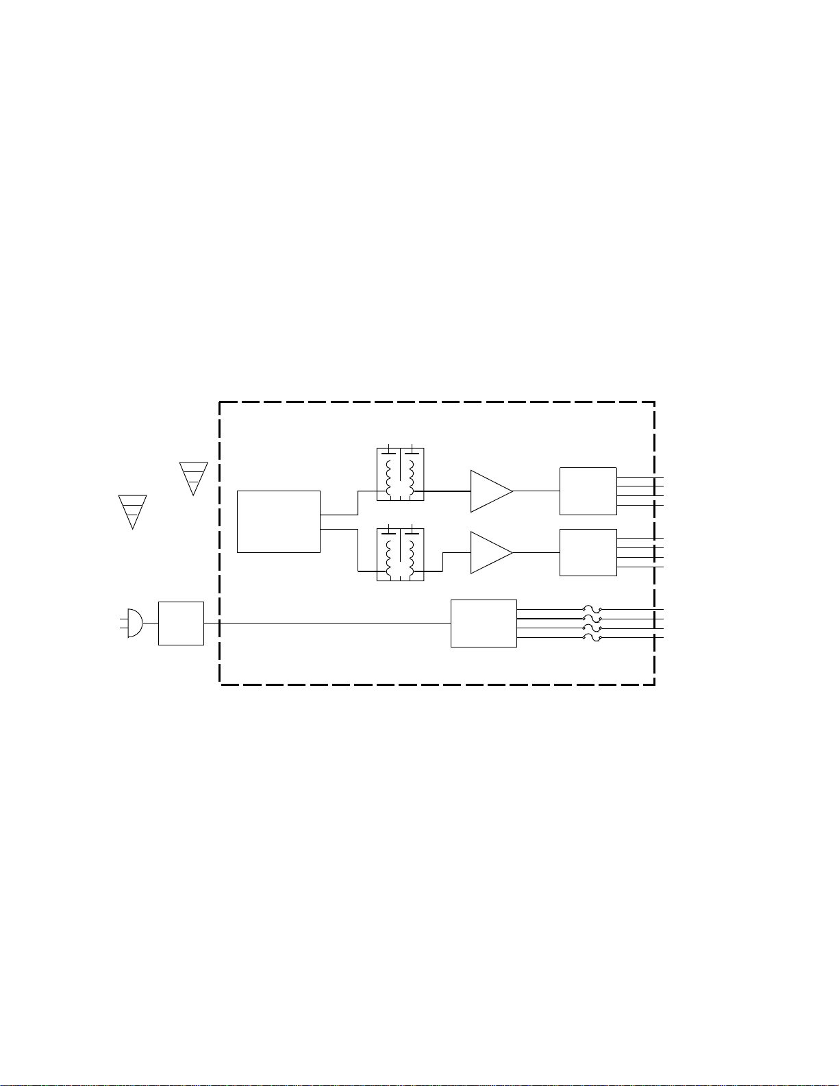
GENERAL TECHNICAL DESCRIPTION
RF FILTERING & DISTRIBUTION
POWER SUPPLY & DISTRIBUTION
POLYFUSES
REGULATOR
HELICAL
RESONATORS
SPLITTER
AND/OR
COMBINER
RF
AMP
SPLITTER
&
ISOLATOR
SPLITTER
&
ISOLATOR
RF
AMP
DM4 Diversity Module
POWER
SUPPLY
RF to
Receivers
12V DC Power
to Receivers
The PRO 4 CHANNEL consists of two sub-systems; the frame which contains the receivers, receiver mounting
hardware, and DC power supply, and the CDM4 RF/power distribution module.
The DM4 RF/power distribution module is the heart of the PRO 4 CHANNEL system. Helical resonators in the front
end of the RF section attenuate out-of-band RF signals preventing intermodulation and front end overload.
Following the resonators is a low noise, low gain RF amplifier designed to evenly compensate for splitter losses in
the stage that follows. A precision splitter/isolator divides the RF signal into four isolated signals preventing
spurious RF coupling between receivers. The splitter/isolator is termination independent which prevents
mismatched or disconnected RF outputs from affecting the other receivers.
Power is supplied to the DM4 module from the DC power supply module mounted on the frame. All power circuits
are protected by internal auto-reset fuses in the DM4. Should the power to one receiver fail, the others will
continue to operate.
Figure 1 - PRO 4 CHANNEL Block Diagram
2
Page 4

FRONT PANEL DESCRIPTION
DM4D MODULE:
POWER SWITCH - Power to the individual receivers is controlled with this switch.
PWR LED - This LED will light when power is provided from the integral DC power supply.
RECEIVER MODULE:
Please refer to the manual for your particular receiver for a complete description.
CH. 1 CH. 2
LECTROSONICS
- -
-24 20 -15 12
-7 -3
+3
0
-12dB
RF
A B
dB AUDIO LEVEL
OFF ON
AUDIO
MUTE
POWER
-20
-50
OUTPUT
ATTENUATOR
-3
I
OPT
BLEND
0dB
A B
CH. 3 CH. 4
LECTROSONICS
- -
-24 20 -15 12
-7 -3
+3
0
-12dB
RF
A B
dB AUDIO LEVEL
OFF ON
AUDIO
MUTE
POWER
-20
-50
OUTPUT
ATTENUATOR
-3
I
OPT
BLEND
0dB
A B
PRO 4 MULTI-CHANNEL
LECTROSONICS
- -
-24 20 -15 12
-7 -3
+3
0
-12dB
RF
A B
dB AUDIO LEVEL
OFF ON
AUDIO
MUTE
POWER
-20
-50
OUTPUT
ATTENUATOR
-3
I
OPT
BLEND
0dB
A B
LECTROSONICS
- -
-24 20 -15 12
-7 -3
+3
0
-12dB
RF
A B
dB AUDIO LEVEL
OFF ON
AUDIO
MUTE
POWER
-20
-50
OUTPUT
ATTENUATOR
-3
I
OPT
BLEND
0dB
A B
Figure 2 - PRO 4 CHANNEL Front Panel
LECTROSONICS
ON
POWER
LECTROSONICS, INC.
FREQUENCIES:
169.505
CH 1
171.045
CH 3
DM4
ANTENNA/POWER
DISTRIBUTION MODULE
170.245
CH 2
171.905
CH 4
3
Page 5

REAR PANEL DESCRIPTION
SERIAL/FREQUENCY LABEL - This label indicates the serial number of the DM4 module. It also indicates the RF
pass-band of the unit. IMPORTANT - The receivers installed in the unit must fall between the frequencies indicated on
the label. Serious signal loss results if the receivers are outside the RF pass-band.
ANTENNA JACK(S) - The Standard system will have one jack for connection to the antenna system. The Diversity
model will have two jacks for two separate antenna systems.
POWER LEADS - These connectors provide power for the individual receivers. Insert the connectors into the jack
provided on each receiver.
INSTALLATION SCREWS - The seven large phillips head screws are used for receiver installation and removal.
See page 5 for further instructions.
AUDIO OUTPUTS
XLR: This XLR type connector supplies a balanced, low impedance output at microphone level. The
audio signal is present on pins 2 and 3, while pin 1 is ground. The output level of this jack is
controlled by the OUTPUT ATTENUATOR control on the front panel of the receiver. Pin 2 is "hot" in
terms of polarity.
1/4": A high level (700mV max.) output at 600 Ohms. This is a three conductor jack with the tip and
ring carrying the signal and the sleeve as shield. The tip is "hot" in terms of polarity. Output from this
jack is controlled by the OUTPUT ATTENUATOR control on the front panel.
RCA: A 1 Volt "line" output at 1K Ohms. The output of this jack is not controlled by the OUTPUT
ATTENUATOR control on the front panel.
AUDIO IN This is an audio input providing a unity gain mixing bus input via a standard RCA jack. Signal applied
to this jack will appear at all three output jacks. This input is provided as a convenience in multiple channel
installations with simple mixing requirements, or for patching in another audio source (tape deck, etc.). Multiple
receivers may be "stacked" with mixed audio output by connecting the LINE OUT jack of one receiver to the AUDIO
IN of the next receiver, and so on. Up to four or five receivers may be "stacked" in this manner before noise buildup becomes objectionable.
B A B A
AB
B A B A
Antenna Antenna Receiver Receiver Receiver Receiver
B A Bal 600 Ohm Out Bal Mic Level Out Lead Line Out Audio In Bracket
(1/4" Phone Jack) (XLR) (RCA) (RCA)
MountingPower
Figure 3 - PRO 4 CHANNEL Rear Panel
4
Page 6

INSTALLATION
The PRO4 CHANNEL is designed to contain up to four receivers. Installation of these receivers is quite simple.
First, place the entire assembly face down on a firm surface and remove the large phillips head screws which hold
the mounting brackets at the rear of the unit. (See Figure 3) Place the receiver(s), front end first against the front
panel. Seat the front end of the receiver into the recessed lip of the PRO4 CHANNEL front panel. The rear panel
of the receiver will extend the same amount as the rear panel of the DM4 module when the unit is properly seated.
Repeat this for each receiver to be installed. After each receiver is in place, install the mounting brackets with the
large phillips head screws to the mounting posts.
At the rear of the unit, attach the antenna leads to each receiver, making sure the BNC connector is securely
twisted and locked into place. The Diversity model will have two antenna leads for each receiver. Be sure to
connect the ANTENNA A plugs with the ANTENNA A jacks and the ANTENNA B plugs with the ANTENNA B jacks.
Set the power switch on the receivers to the ON position. Antenna leads serving empty slots can be left open, but
best performance will be had if they are terminated with 50 Ohms.
At the rear panel, insert the power connectors into the power jack of each receiver.
OPERATING INSTRUCTIONS
After all the receivers have been installed, check to be sure that the receivers have their power switch set to ON.
Audio leads should be balanced audio cables leading to the mixer or recorder.
Turn the system on by switching the power switch on the DM4 module to ON. The power indicator LEDs should
light on all the receivers and the DM4.
Operate the wireless microphone according to the instructions included with the systems.
5
Page 7

TROUBLESHOOTING
SYMPTOM POSSIBLE CAUSE
NO POWER LEDs OR AUDIO 1) Power switch in the OFF position. Switch to ON.
POWER LED LIGHTS ON DM4
BUT NO LIGHTS ON RECEIVERS
POWER AND MODULATION LEDs ON,
BUT NO AUDIO
POWER LEDs ON, NO MODULATION LEDs 1) Transmitters not on or in mute position. Check
POOR SIGNAL/NOISE OR DROPOUTS 1) Antenna leads not connected, Check antennas.
1) Power leads in back not connected to receivers.
Check power connections.
1) No audio connection to recorder or mixer. Check
connections.
transmitters.
2) Transmitters have dead batteries, check batteries.
2) Main antenna(s) improperly connected. Check
antenna(s).
3) Antenna "blocked" or in poor RF location. Try
repositioning the antenna(s).
4) Transmitter modulation improperly set. Check mod
levels.
6
Page 8

SPECIFICATIONS
DM4/DM4D RF/POWER DISTRIBUTION MODULE
RF Gain: 1.5 dB
RF Output:
DM4: Four outputs, 50 Ohm, BNC
DM4D: Eight outputs, 50 Ohm, BNC
Filtering: Two section helical resonator per antenna
Third Order Intercept: +25 dBm
Power Input: 120 VAC
Power Consumption:
Diversity: 18 Watts
Standard: 10 Watts
Connectors:
RF: BNC
POWER OUTPUT: 2.5mm power jack
(A/D Electronics part # ADC-014)
Short Circuit Protection: Auto-reset thermal fuses
PRO4 CHANNEL SYSTEM
Construction: Machined aluminum panels, housings, and
mechanical parts.
Dimensions: 19" wide, 7" high, 8.25" deep
Weight: 17 lbs, 6ozs including 4 R185 receivers
7
Page 9

SERVICE AND REPAIR
If your system malfunctions, you should attempt to correct or isolate the trouble before concluding that the
equipment needs repair. Make sure you have followed the setup procedure and operating instructions.
Check out the inter-connecting cords and then go through the TROUBLE SHOOTING section in the
manual
We strongly recommend that you do not try to repair the equipment yourself and do not have the local
repair shop attempt anything other than the simplest repair. If the repair is more complicated than a
broken wire or loose connection, send the unit to the factory for repair and service. Don’t attempt to adjust
any controls inside the units. Once set at the factory, the various controls and trimmers do not drift with
age or vibration and never require readjustment. There are no adjustments inside that will make a
malfunctioning unit start working.
LECTROSONICS service department is equipped and staffed to quickly repair your equipment.
In-warranty repairs are made at no charge in accordance with the terms of the warranty. Out of warranty
repairs are charged at a modest flat rate plus parts and shipping. Since it takes almost as much time and
effort to determine what is wrong as it does to make the repair, there is a charge for an exact quotation.
We will be happy to quote approximate charges by phone for out of warranty repairs.
RETURNING UNITS FOR REPAIR
You will save yourself time and trouble if you will follow the steps below:
A. DO NOT return equipment to the factory for repair without first contacting us by letter or by phone.
We need to know the nature of the problem, the model number and the serial number of the
equipment. We also need a phone number where you can be reached 8 am to 4 pm (Mountain
Standard Time).
B. After receiving your request, we will issue you a return authorization number (R.A.). This number will
help speed your repair through our receiving and repair departments. The return authorization number
must be clearly shown on the outside of the shipping container.
C. Pack the equipment carefully and ship to us, shipping costs prepaid. If necessary, we can provide you
with the proper packing materials. UPS is usually the best way to ship the units. Heavy units should
be "double-boxed" for safe transport.
D. We also strongly recommend that you insure the equipment, since we cannot be responsible for loss
of or damage to equipment that you ship. Of course, we insure the equipment when we ship it back
to you.
Mailing address: Shipping address:
Lectrosonics, Inc. Lectrosonics, Inc.
PO Box 15900 581 Laser Rd.
Rio Rancho, NM 87174 Rio Rancho, NM 87124
USA USA
Telephones:
Regular: (505) 892-4501
WATS: (800) 821-1121
FAX: (505) 892-6243
8
Page 10

LIMITED ONE YEAR WARRANTY
The equipment is warranted for one year from date of purchase against defects
in materials or workmanship provided it was purchased from an authorized
dealer. This warranty does not cover equipment which has been abused or
damaged by careless handling or shipping. This warranty does not apply to
used or demonstrator equipment.
Should any defect develop, we will, at our option, repair or replace any
defective parts without charge for either parts or labor. If we cannot correct the
defect in your equipment, we will replace it at no charge with a similar new item.
We will pay for the cost of returning your merchandise to you.
This warranty applies only to items returned to us, shipping costs prepaid, within
one year from the date of purchase.
This warranty gives you specific legal rights. You may have additional legal
rights which vary from state to state.
LECTROSONICS, INC.
581 LASER ROAD
RIO RANCHO, NM 87124 USA
 Loading...