

Page 1
Octopack
Portable Receiver Multicoupler
INSTRUCTION MANUAL
Power and RF Distribution
for SRa Series Compact Receivers
Fill in for your records:
Serial Number:
Purchase Date:
Rio Rancho, NM, USA
www.lectrosonics.com
Page 2

OCTOPACK
2
LECTROSONICS, INC.
Page 3

Receiver Multicoupler
FCC Compliance
This device complies with Part 15 of the FCC Rules. Operation is subject to the following two
conditions: (1) This device may not cause harmful interference, and (2) this device must accept any interference received, including interference that may cause undesired operation.
The Octopack has been tested and found to comply with the limits for a Class B digital
device, pursuant to Part 15 of the FCC Rules. These limits are designed to provide reasonable protection against harmful interference in a residential installation. However, there is no
guarantee that interference will not occur in a particular installation. Ths equipment generates,
uses and can radiate radio frequency energy and, if not installed and used in accordance
with the instructions, may cause interference to radio receivers. Changes or modifications to
this equipment not expressly approved by Lectrosonics, Inc. could void the user’s authority to
operate it.
If this equipment does cause harmful interference to radio or television reception, which can
be determined by turning the equipment off and on, the user is encouraged to try to correct
the interference by one or more of the following measures:
• Reorientorrelocatethereceivingantenna
• Increasetheseparationbetweenthisequipmentandreceiver
• Connectthisequipmentintoanoutletonacircuitdifferentfromthatwhichthereceiveris
connected
• Consultthedealeroranexperiencedradio/TVtechnicianforhelp
Rio Rancho, NM
3
Page 4

OCTOPACK
Table of Contents
General Technical Description ..........................................................................................................................................................5
Control Panel ......................................................................................................................................................................................6
Battery Panel .......................................................................................................................................................................................7
Side Panel ...........................................................................................................................................................................................7
Receiver Installation...........................................................................................................................................................................8
Receiver Removal...............................................................................................................................................................................9
Antenna Power Jumpers .................................................................................................................................................................10
Antenna Bandwidth and Requirements .........................................................................................................................................11
Antenna/Block Reference Chart......................................................................................................................................................12
Replacement Parts & Accessories .................................................................................................................................................13
Optional Accessories .......................................................................................................................................................................14
Troubleshooting ................................................................................................................................................................................15
Specifications ...................................................................................................................................................................................16
Service and Repair ...........................................................................................................................................................................17
Returning Units for Repair ..............................................................................................................................................................17
4
LECTROSONICS, INC.
Page 5
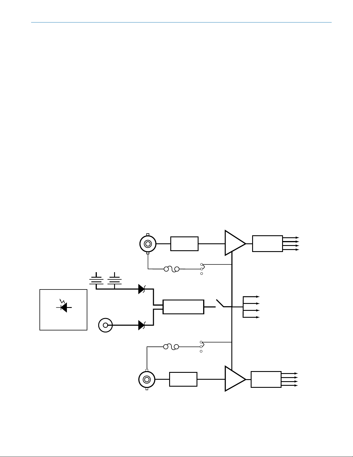
General Technical Description
RF IN
FILTER
COMPARATOR
RF IN
FILTER
RF OUT
RF OUT
SPLITTER
SPLITTER
DC OUT
BATTERIES
EXT DC
RF
AMP
300 mA
DC (+)
DC (+)
ANT PWR
ENABLE
300 mA
ANT PWR
ENABLE
BLINK: BATTERY
STEADY: EXT DC
POWER LED
RF
AMP
Receiver Multicoupler
To address an increasing demand for more wireless
channels in location production, the Octopack combines up to four SRa Series compact receivers into
a lightweight, rugged assembly with self-contained
power supply, power distribution and antenna signal
distribution. This versatile production tool provides
up to eight audio channels in a tiny package ready to
work in applications from production cart to a portable
mixing bag.
High quality antenna distribution requires the use of ultra quiet RF amps plus isolated and optimally matched
signal paths through the circuitry to ensure equal performance from all connected receivers. In addition, the
amplifiers used must be high overload types to avoid
generating IM (intermodulation) within the multicoupler itself. Octopack meets these requirements for RF
performance.
The wide bandwidth of the antenna multicoupler allows
the use of receivers over a wide range of frequency
blocks to simplify frequency coordination. Receivers
can be installed in any of the four slots, or a slot can
be left empty with no need to terminate the RF coaxial
connections. The receivers interface with the Octopack
board via the 25-pin Unislot adapter, so in many cases,
the receivers can be moved from the Octopack to a
camera without having to change the adapter.
Antenna inputs are standard 50 ohm BNC jacks. DC
power on the jacks can be switched on for use with
Lectrosonics UFM230 RF amplifiers or the ALP650
powered antenna for long coaxial cable runs. An LED
next to the recessed switch indicates the power status.
The front panel is designed to accept the standard or
the “5P” version of the receiver which provides audio
outputs on the front panel of the receiver. The second
set of audio outputs can be used for a redundant feed
to a recorder in addition to the main outputs that would
typically feed wireless transmitters in a bag system, or
a mixer on a sound cart.
The Octopack housing is constructed of machined alu-
minumwithareinforcedrear/bottompaneltoprotect
the batteries and power jack. The front panel includes
two rugged handles that protect the connectors, receiver front panels and antenna jacks.
Rio Rancho, NM
5
Page 6
OCTOPACK
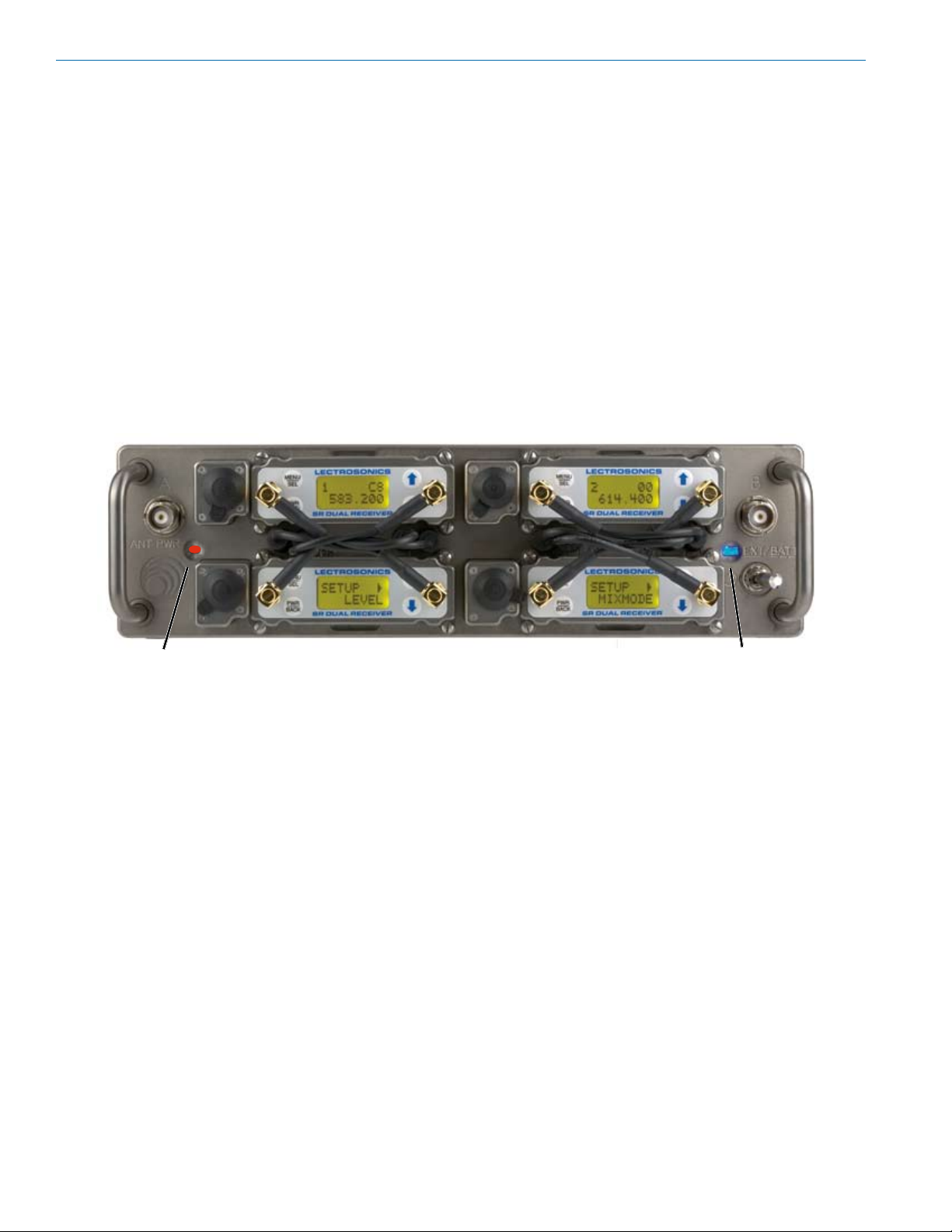
Control Panel
RF Signal Distribution
Each antenna input is routed through a high quality
RF splitter to coaxial leads on the control panel. Gold
plated right angle connectors mate to the SMA jacks
on SRa Series receivers. Frequencies of the installed
receivers should be within the frequency range of the
antenna multicoupler.
Power Indication
The power switch locks in position to prevent accidental turn off. When power is engaged, the LED next to
the switch illuminates to indicate the source, remaining
steady when external power is selected and blinking
slowly when the batteries are providing power.
Antenna Power
A recessed switch on the left side of the control panel
enables and disables DC power passed from the
power supply to the BNC antenna connectors. This
provides powering of remote RF amplifiers through
the attached coaxial cable. The LED glows red when
power is enabled.
Receiver Versions
SRa and SRa5P versions of the receiver can be
installed in any combination. Earlier versions of the
receivers with fixed antennas cannot be connected to
the multicoupler antenna feeds, however, the power
and audio connections will still be made via the 25-pin
connector.
Switch
Power Status LEDAntenna Power
6
LECTROSONICS, INC.
Page 7

Receiver Multicoupler
Battery Panel
The passband of the multicoupler is marked on the
label on the housing cover next to the battery panel.
IMPORTANT - The frequency of the receivers
installed in the unit must fall within the passband
indicated on the label. Serious signal loss can
result if the receiver frequencies are outside the
Octopack RF passband.
External DC Power
Any external power source can be used if it has the
correct connector, voltage and current capacity. Polarity, voltage range and maximum current consumption
are engraved next to the power jack.
Battery Power
Therear/bottompanelprovidesalockingpowerjack
and mounting for two L or M style rechargeable batteries. The batteries must be charged separately with the
charger supplied by the manufacture since there is no
charging circuitry in the Octopack.
Automatic Backup Power
When batteries and external DC are both connected,
power is drawn from the source with the highest voltage. Typically, the external source provides a higher
voltage than the batteries, and in the event it fails, the
batteries will immediately take over and the power
LED will begin to blink slowly. The source selection is
handled by circuitry rather than a mechanical switch or
relay for reliability.
Side Panel
Eight balanced outputs are provided on the side panel
of the multicoupler. When the receivers operate in a
2-channel mode, each jack provides a separate audio
channel. In the ratio diversity mode, the receivers
are paired, so adjacent output jacks deliver the same
audio channel.
The connectors are standard TA3M types, with the
same pinout numbering as 3-pin XLR connectors.
Rio Rancho, NM
Battery Retainer Tabs - Press to Release
External DC Power Jack
4-pin Hirose
External DC Power Jack
Coaxial Locking Type
7
Page 8

OCTOPACK
Receiver Installation
First install the SRUNI rear panel adapter.
The mating 25-pin connector inside each slot on the
Octopack provides power and audio connections.
Gently insert the receivers into the slots. A guide
around each internal connector centers the housing to
align the connector pins.
Plastic inserts are provided to cover empty slots. Sockets in the insert are sized to store loose antenna leads.
RF leads are connected to the receivers in a crisscross pattern to avoid sharp bends in the cables. The
leads are marked on the control panel as B on the
left and A on the right side of each slot. The antenna
inputs on the receivers are the opposite, with A on the
left and B on the right. The right angle connectors help
to maintain a low profile and visibility of the LCDs on
the receivers.
“A” antenna inputs
“B” coaxial feeds “A” coaxial feeds
“B” antenna inputs
Sockets in the slot covers are provided to store unused
RF leads and keep the right angle connectors clean.
8
LECTROSONICS, INC.
Page 9

Receiver Removal
Receiver Multicoupler
Disconnect all four mounting screws on
each receiver from the Octopack panel
A handy tool, constructed of Delrin, is provided to aid
in removing the receivers and to loosen overly tightened coaxial connectors.
Normally the hex nuts on the coaxial RF leads are
secured and removed by hand. The tool is provided if
the nuts cannot be removed by hand.
DO NOT overtighten the nuts with the wrench.
The open end wrench is used to loosen coaxial
connector nuts that have been overtightened.
The supplied tool is stored in a clip on the battery panel
It is difficult to remove the receivers by hand due to the
friction in the 25-pin connector in the slot and the difficulty of gripping the receiver housing. The flat end of
the tool is used to remove the receivers by prying the
housing upward in the notch next to the slot.
DO NOT remove the receivers by pulling on the
antennassincetheantennasand/orconnectors
can be damaged.
Pry the receiver housing upward in the notch to release
the 25-pin connector
Rio Rancho, NM
9
Page 10

OCTOPACK
Antenna Power Jumpers
Power for Lectrosonics remote RF amplifiers is provided by DC voltage from the power supply passed
directly to the BNC jacks on the control panel. An
illuminated switch on the left side of the control panel
enables and disables the power. A 300 mA polyfuse
protects against excessive current in each BNC output.
Install the jumpers towards the center of the circuit
board to enable the antenna power, and towards the
outside of the circuit board to disable it.
Insert jumper toward center of
board to enable antenna power
Antenna power switch glows red
when DC power is enabled.
NOTE: The control panel LED will continue to
indicate that antenna power is turned on even if
one or both jumpers is set to disable it.
Antenna power can be disabled at each of the BNC
connectors with jumpers on the internal circuit board.
Remove the cover panel to access the jumpers.
Threaded power connector
Remove the eight smaller screws from the housing
and the three larger screws from the support posts.
Jumpers are located near the corners of the board.
Antenna Power Jumpers
Enable
Insert jumper toward center of
board to enable antenna power
Enable
NOTE: No damage will occur if a standard
antenna is connected while antenna power is
enabled.
Place the ferrules on top of the support posts before
attaching the cover. Be careful not to overtighten the
screws.
Place ferrules on top
of the support posts
before attaching cover.
10
NOTE: When using any amplifier other than
Lectrosonics models, make certain that the DC
voltage and power consumption are within an
acceptable range.
LECTROSONICS, INC.
Page 11

Antenna Bandwidth and Requirements
The design of Lectrosonics wideband multicouplers
helps deal with a changing RF spectrum, however, it
also introduces the requirement for specific or more
advanced antennas to provide maximum operating
range. Simple whip antennas cut to a single frequency
block are inexpensive and effective at covering a 50 to
75 MHz band, but will not provide adequate coverage
for the entire range of a wideband antenna multicoupler. Following are the antenna options available from
Lectrosonics:
Lectrosonics Antennas:
Model Type Bandwidth
MHz
A500RA (xx) Rt. angle whip 25.6
ACOAXBNC(xx) Coaxial 25.6
SNA600 Tunable dipole 100
ALP500 Log-periodic 450 - 850
ALP620 Log-periodic 450 - 850
ALP650(w/amp) Log-periodic 537 - 767
ALP650L(w/amp) Log-periodic 470 - 692
In the table, (xx) with the whip and coaxial antenna
model numbers refers to the specific frequency block
that the antenna is precut to use. The SNA600 model
is tunable to move the center frequency of its 100 MHz
bandwidth up and down from 550 to 800 MHz.
The greater the mismatch of frequencies between
the antenna and the receiver, the weaker the signal
will be, and the shorter the maximum operating range
of the wireless system. Experimentation and checking the range before the production starts is always
a good idea, and is mandatory if the frequencies of
the antenna and receiver do not match exactly. On
many production sets, the short operating range that
is needed may allow the use of a slightly mismatched
whip antenna.
In general, using a whip antenna one block above or
below the receiver range will provide adequate range,
often with no noticeable difference from the correct
antenna.
Use the RF level meter on the receiver to check the
received signal strength. Keep in mind that the signal
level varies wildly as the system operates, so be sure
to conduct a walk test through the area to identify locations where the signal drops to very low levels.
There are also many antennas made by other companies, which are easily found by searching for their web
sites. Use search terms like “Log-periodic,” “directional,”
“broadband,” etc. A specialized type of omni-directional
antenna is called a “discone.” A DIY “hobby kit” instruction manual for building a discone is on this web site:
ALP500
* See Antenna/Block Reference
Chart on next page
Receiver Multicoupler
A500RA
(precut to block)
ACOAXBNC
(precut to block)
SNA600
ALP620
ALP650
http://www.ramseyelectronics.com/downloads/manuals/DA25.pdf
Rio Rancho, NM
11
Page 12

OCTOPACK
333231
21
22
23
24
25
26
27
28
29
30
Frequency Blocks
Colored cap
20
Note: This line should be 6.00" long.
Whip Length
944
779
470
19
Antenna/Block Reference Chart
The A8U whip UHF whip antenna is factory cut to a
specific frequency block as shown in the table below.
A colored cap and label are used on blocks 21 through
29, and a black cap and label are used on the other
blocks to denote the frequency range of each model.
The A8UKIT is is also available to construct an antenna as needed. The chart is used to cut the length correctly and for identifying the frequency of an antenna
that is not marked.
BLOCK FREQUENCY CAP ANTENNA
RANGE COLOR WHIP LENGTH
470 470.100-495.600 Blackw/Label 5.48”
19 486.400-511.900 Blackw/Label 5.20”
20 512.000-537.500 Blackw/Label 4.95”
21 537.600 - 563.100 Brown 4.74”
22 563.200 - 588.700 Red 4.48”
23 588.800 - 614.300 Orange 4.24”
24 614.400 - 639.900 Yellow 4.01”
25 640.000 - 665.500 Green 3.81”
26 665.600 - 691.100 Blue 3.62”
27 691.200-716.700 Violet(Pink) 3.46”
28 716.800 - 742.300 Grey 3.31”
29 742.400 - 767.900 White 3.18”
30 768.000-793.500 Blackw/Label 3.08”
31 793.600-819.100 Blackw/Label 2.99”
32 819.200-844.700 Blackw/Label 2.92”
33 844.800-861.900 Blackw/Label 2.87”
779 779.125-809.750 Blackw/Label 3.00”
944 944.100-951.900 Blackw/Label 2.70”
The lengths shown are specifically for the A8U whip
antenna with a BNC connector, as determined by measurements with a network analyzer. The optimal length
of the element in other designs will likely be different
than those shown in this table, but since the bandwidth
is typically wider than the specified block, the exact
length is not critical for useful performance.
12
Note: Not all Lectrosonics products are built on all of the blocks covered in
this chart.
LECTROSONICS, INC.
Page 13

Replacement Parts & Accessories
P1246 Delrin tool for receiver removal and loosening coaxial antenna leads
P1139 Blank slot cover
21746 Power cable with locking, right angle connector to stripped and tinned; 12 inch length
Receiver Multicoupler
A8U KIT Whip Antenna with BNC Connector and color coded end caps. Includes cutting template
and table for all frequency blocks.
Rio Rancho, NM
13
Page 14

OCTOPACK
Optional Accessories
Coaxial Cables
A variety of low loss coaxial cables are available to
avoid signal loss through longer runs between antenna
and receiver. Lengths include 2, 15, 25, 50 and 100
foot lengths. The longer cables are constructed of
Belden 9913F with special connectors that terminate
directly to BNC jacks, eliminating the need for adapters
that can introduce additional signal loss.
Customized RF Distribution and Routing
Customized antenna and RF distribution is easy to
configure using the UFM230 amplifier, BIAST power
inserterandseveralRFsplitter/combiners.These
professional grade components preserve signal quality
and suppress noise and intermodulation.
ARG Series Coaxial Cables
UFM230 Filter/Amp
Bias-T Power Inserter
8-Way Splitter/Combiner
4-way Splitter/Combiner
2-way Splitter/Combiner
14
LECTROSONICS, INC.
Page 15

Receiver Multicoupler
Troubleshooting
SYMPTOM POSSIBLE CAUSE
NO POWER LED INDICATION 1) Power switch in the OFF position.
2) Batteries low or dead
3) External DC source too low or disconnected
NOTE: If the power supply voltage drops too low for normal operation, the LCD on the receivers will display a “Low
Battery” warning every few seconds. When the voltage drops to 5.5 volts, the LCD will dim and the audio output level
of the receivers will decrease.
SHORT OPERATING RANGE, DROPOUTS
OR WEAK OVERALL RF LEVEL 1) Passbands of Octopack and antennas may be different;
(check RF level with receiver LCD) frequency of transmitter must be inside of both passbands
2) Antenna power switched off when external RF amplifiers are
being used
3) Antenna power interrupted by polyfuse; current consumption
of remote amplifier must be less than 300 mA on each BNC
4) Coaxial cable runs too long for the cable type
Rio Rancho, NM
15
Page 16

OCTOPACK
Specifications
RF Bandwidth (3 versions): Low: 470 to 691 MHz
Mid: 537 to 768 MHz (export)
High: 640 to 862 MHz (export)
RF Gain 0 to 2.0 dB across bandwidth
Output Third Order Intercept: +41 dBm
1 dB Compression: +22 dBm
Antenna Inputs: Standard 50 ohm BNC jacks
Antenna Power: Voltage is passed through from main power source; 300 mA polyfuse in each BNC output
Receiver RF feeds: 50 ohm right angle SMA jacks
Internal Battery Type: L or M style rechargeable
External Power Requirement: 8 to 18 VDC; 1300 mA at 8 VDC
Power Consumption: 1450 mA max. with 7.2 V battery power; (both antenna power supplies on)
Dimensions: H 2.75 in. x W 10.00 in. x D 6.50 in.
H 70 mm x W 254 mm x D 165 mm
Weight: Assembly only: 2 lbs., 9 ozs. (1.16 kg)
With 4-SRa5P receivers: 4 lbs., 6 ozs. (1.98 kg)
Specifications subject to change without notice
16
LECTROSONICS, INC.
Page 17

Receiver Multicoupler
Service and Repair
If your system malfunctions, you should attempt to correct or isolate the trouble before concluding that the equipment needs repair. Make sure you have followed the setup procedure and operating instructions. Check the interconnecting cables and then go through the Troubleshooting section in this manual.
We strongly recommend that you do not try to repair the equipment yourself and do not have the local repair shop
attempt anything other than the simplest repair. If the repair is more complicated than a broken wire or loose connection, send the unit to the factory for repair and service. Don’t attempt to adjust any controls inside the units. Once
set at the factory, the various controls and trimmers do not drift with age or vibration and never require readjustment.
There are no adjustments inside that will make a malfunctioning unit start working.
LECTROSONICS’ Service Department is equipped and staffed to quickly repair your equipment. In warranty repairs
are made at no charge in accordance with the terms of the warranty. Out-of-warranty repairs are charged at a modest flat rate plus parts and shipping. Since it takes almost as much time and effort to determine what is wrong as it
does to make the repair, there is a charge for an exact quotation. We will be happy to quote approximate charges by
phone for out-of-warranty repairs.
Returning Units for Repair
For timely service, please follow the steps below:
A. DO NOT return equipment to the factory for repair without first contacting us by email or by phone. We need
to know the nature of the problem, the model number and the serial number of the equipment. We also need a
phone number where you can be reached 8 A.M. to 4 P.M. (U.S. Mountain Standard Time).
B. After receiving your request, we will issue you a return authorization number (R.A.). This number will help speed
your repair through our receiving and repair departments. The return authorization number must be clearly
shown on the outside of the shipping container.
C. Pack the equipment carefully and ship to us, shipping costs prepaid. If necessary, we can provide you with the
proper packing materials. UPS is usually the best way to ship the units. Heavy units should be “double-boxed”
for safe transport.
D. We also strongly recommend that you insure the equipment, since we cannot be responsible for loss of or dam-
age to equipment that you ship. Of course, we insure the equipment when we ship it back to you.
Lectrosonics USA:
Mailing address: Shipping address: Telephone:
Lectrosonics, Inc. Lectrosonics, Inc. (505) 892-4501
PO Box 15900 581 Laser Rd. (800) 821-1121 Toll-free
Rio Rancho, NM 87174 Rio Rancho, NM 87124 (505) 892-6243 Fax
USA USA
Web: E-mail:
www.lectrosonics.com sales@lectrosonics.com
Lectrosonics Canada:
Mailing Address: Telephone: E-mail:
49 Spadina Avenue, (416) 596-2202 Sales: colinb@lectrosonics.com
Suite 303A (877) 753-2876 Toll-free Service: joeb@lectrosonics.com
Toronto,OntarioM5V2J1 (877-7LECTRO)
(416) 596-6648 Fax
Rio Rancho, NM
17
Page 18

OCTOPACK
18
LECTROSONICS, INC.
Page 19

Receiver Multicoupler
Rio Rancho, NM
19
Page 20

581 Laser Road NE • Rio Rancho, NM 87124 USA • www.lectrosonics.com
(505) 892-4501 • (800) 821-1121 • fax (505) 892-6243 • sales@lectrosonics.com
LIMITED ONE YEAR WARRANTY
The equipment is warranted for one year from date of purchase against defects in
materials or workmanship provided it was purchased from an authorized dealer. This
warranty does not cover equipment which has been abused or damaged by careless
handling or shipping. This warranty does not apply to used or demonstrator equipment.
Should any defect develop, Lectrosonics, Inc. will, at our option, repair or replace any
defective parts without charge for either parts or labor. If Lectrosonics, Inc. cannot
correct the defect in your equipment, it will be replaced at no charge with a similar new
item. Lectrosonics, Inc. will pay for the cost of returning your equipment to you.
This warranty applies only to items returned to Lectrosonics, Inc. or an authorized
dealer, shipping costs prepaid, within one year from the date of purchase.
This Limited Warranty is governed by the laws of the State of New Mexico. It states the
entire liablility of Lectrosonics Inc. and the entire remedy of the purchaser for any
breach of warranty as outlined above. NEITHER LECTROSONICS, INC. NOR
ANYONE INVOLVED IN THE PRODUCTION OR DELIVERY OF THE EQUIPMENT
SHALL BE LIABLE FOR ANY INDIRECT, SPECIAL, PUNITIVE, CONSEQUENTIAL,
OR INCIDENTAL DAMAGES ARISING OUT OF THE USE OR INABILITY TO USE
THIS EQUIPMENT EVEN IF LECTROSONICS, INC. HAS BEEN ADVISED OF THE
POSSIBILITY OF SUCH DAMAGES. IN NO EVENT SHALL THE LIABILITY OF
LECTROSONICS, INC. EXCEED THE PURCHASE PRICE OF ANY DEFECTIVE
EQUIPMENT.
This warranty gives you specific legal rights. You may have additional legal rights which
vary from state to state.
01 September 2010
 Loading...