

M2T
Digital IEM Transmitter
INSTRUCTION MANUAL
DanteTM is a trademark of Audinate Pty Ltd.
Fill in for your records:
Serial Number:
This device has not been authorized as required by the rules of the Federal
Communications Commission. This device is not, and may not be, offered for sale
or lease, or sold or leased, until authorization is obtained.
Purchase Date:
Rio Rancho, NM, USA
www.lectrosonics.com

M2T
Table of Contents
Introduction .............................................................................................................................................................................................3
What is Dante? .....................................................................................................................................................................................3
Panels and Features ...............................................................................................................................................................................4
M2T Front Panel ...................................................................................................................................................................................4
M2T Back Panel ....................................................................................................................................................................................4
Operating Instructions ..........................................................................................................................................................................5
IR (infrared) Port ...................................................................................................................................................................................5
USB Port ...............................................................................................................................................................................................5
Headphone Volume Adjustment ............................................................................................................................................................ 5
Dante Ports (optional) ...........................................................................................................................................................................5
Ethernet Port .........................................................................................................................................................................................5
Power Inlet ............................................................................................................................................................................................5
Navigating the Menus ...........................................................................................................................................................................5
LCD Menu Map ........................................................................................................................................................................................6
Menu Item Descriptions .........................................................................................................................................................................7
RF Enable/Level ....................................................................................................................................................................................7
RF Tuning ..............................................................................................................................................................................................7
Sync Scan .............................................................................................................................................................................................7
Sync Settings ........................................................................................................................................................................................7
Sync FlexList™ .....................................................................................................................................................................................7
Audio Level/Trim ....................................................................................................................................................................................8
Audio Input Type ...................................................................................................................................................................................8
Audio Polarity ........................................................................................................................................................................................8
Headphone Monitor ..............................................................................................................................................................................8
Front Panel Setup .................................................................................................................................................................................8
Network Settings ...................................................................................................................................................................................8
Edit Names ...........................................................................................................................................................................................8
Restore Defaults ...................................................................................................................................................................................8
About .....................................................................................................................................................................................................8
Links ......................................................................................................................................................................................................9
System Setup Procedures .....................................................................................................................................................................9
Summary of Steps ................................................................................................................................................................................9
Accessories ..........................................................................................................................................................................................10
Specifications and Features ................................................................................................................................................................11
Specifications ......................................................................................................................................................................................11
Wireless Designer Software and USB Driver .....................................................................................................................................12
Wireless Designer Software and USB Driver .....................................................................................................................................13
Software Installer ................................................................................................................................................................................13
Firmware Update Instructions .............................................................................................................................................................13
Service and Repair ...............................................................................................................................................................................14
Returning Units for Repair ..................................................................................................................................................................14
Consumer Alert for US Users - FCC Order DA 10-92
Most users do not need a license to operate this wireless microphone system. Nevertheless, operating this microphone system without a license is subject to certain restrictions: the system may not cause harmful interference; it
must operate at a low power level (not in excess of 50 milliwatts); and it has no protection from interference received
from any other device. Purchasers should also be aware that the FCC is currently evaluating use of wireless mi
crophone systems, and these rules are subject to change. For more information, call the FCC at 1-888- CALL-FCC
(TTY: 1-888-TELL-FCC) or visit the FCC’s wireless microphone website at www.fcc.gov/cgb/wirelessmicrophones.
To operate wireless microphone systems at power greater than 50mW, you must qualify as a Part 74 user and be
licensed. If you qualify and wish to apply for a license go to: http://www.fcc.gov/Forms/Form601/601.html
2
LECTROSONICS, INC.
-

Introduction
The M2T Digital Half-Rack Transmitter with analog and
optional digital Dante™ network audio inputs presents
an excellent sounding IEM system with a unique level of
performance in a wireless in-ear monitor platform. With
ultra-low latency, 24-bit audio, digital RF modulation
and two stereo digital channels, the M2T provides a
truly unique IEM product for demanding, professional
applications.
The M2T includes a USB port for firmware updates and
an IR port for fast setup. A large, high resolution, backlit
LCD and large membrane switches provide an intuitive
interface that is highly visible in daylight or dimly lit
conditions.
The half-rack transmitter provides four audio inputs which
can be individually configured to be analog or Dante
compatible. The input connectors are full size XLR/TRS
combo types for balanced line level analog signals. Input
preamp circuits use a special balanced amplifier with very
high common mode rejection to minimize hum and noise.
Analog signals are converted to an internal 24-bit digital
format which is then encoded, organized into packets,
and passed to an RF modulator. The modulated RF signal
is filtered before and after amplification to suppress outof-band noise and spurious signals.
Conventional in-ear wireless monitor systems rely
on decades-old technology: FM transmission with
multiplexed, companded audio. The M2T Transmitter
employs unique technology to provide ruler-flat frequency
response from 20 Hz to 15 kHz and maximum channel
separation. In addition, the digital audio eliminates a
compandor and the associated artifacts. The result is
crystal clear sound and extremely low distortion
of <0.15%.
The M2T is designed and developed with the professional
touring, installation, theater and broadcast customers in
mind. The transmitter chassis is all-metal. The front panel
is an aluminum extrusion with a durable powder coat
finish.
Digital IEM Transmitter
What is Dante?
Audinate’s patent pending Dante™ technology is a
flexible Internet Protocol (IP) and Ethernet based digital
AV network technology that eliminates the many bulky
cables needed to provide point-to-point wiring for analog AV installations.
With Dante, existing infrastructure can be used for high
performance audio as well as for ordinary control, monitoring or business data traffic. Digital networks utilize
standard IP over Ethernet offering high bandwidth capable of transporting hundreds of high quality channels
over Gigabit Ethernet.
Set-up and configuring the system is made easy as
well, saving enormous installation costs and long term
cost of ownership on a digital network. The physical
connecting point is irrelevant: audio signals can be
made available anywhere and everywhere. Patching
and routing now become logical functions configured in
software, not via physical wired links
Summary of Dante Benefits
• Plug-and-play technology – automatic discovery
and simple signal routing
• Reduced Cost & Complexity- No special skills
required to set up audio networking
• Sample accurate playback synchronization
• Add/remove/rearrange components at will
• Deterministic latency throughout the network
• Support mixed bit depths and mixed sample
rates over one network
• Scalable, flexible network topology supporting a
large number of senders and receivers
• Supports 1Gbps networks
• Supports a single integrated network for audio,
video, control, monitoring
• Uses inexpensive, off-the-shelf computer
networking equipment
Firmware updates are made via the USB port on the
front panel of the housing. The procedure is very simple
using a standard micro USB cable connected to a PC.
Setup and adjustment are enabled through a backlit LCD,
membrane switches and an intuitive menu structure.
Rio Rancho, NM
3
M2T
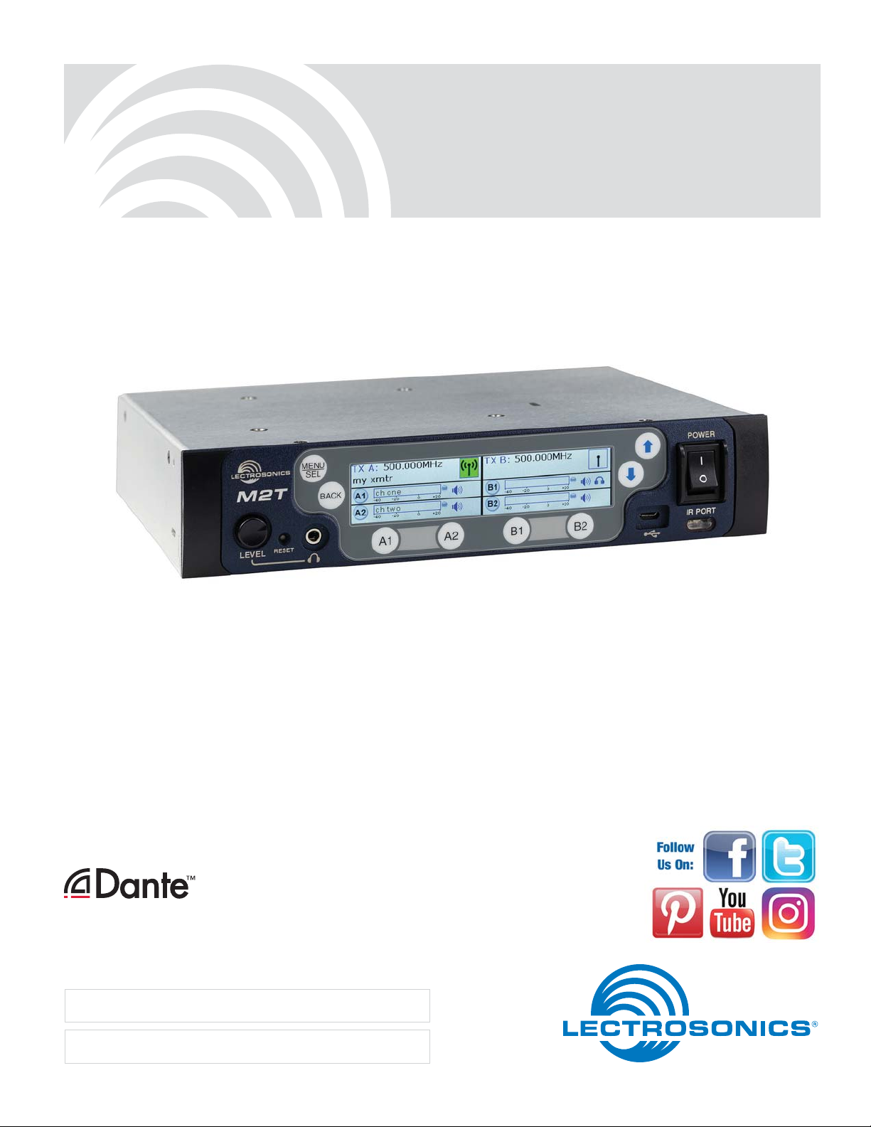
Panels and Features
M2T Front Panel
Menu/Select
Reset Button
Headphone Volume
Adjustment
M2T Back Panel
Antenna
Jack
Return to
previous screen
Headphone Jack
Dante Ports
Channel
Function Buttons
Menu navigation
buttons
USB Port
Power switch
IR Port
Antenna
Jack
XLR/TRS Combo Analog
Power Inlet
4
Input Connectors
Ethernet Port
LECTROSONICS, INC.
Digital IEM Transmitter
Operating Instructions
IR (infrared) Port
Settings, including frequency, name, limiter, mix mode,
etc. can be transferred to and from the M2T transmitter
via this port to an IR enabled receiver to simplify setup.
USB Port
For firmware updates and connection to Wireless Designer Software.
Reset Button
For MCU recovery in the event of an interrupted firmware update.
Headphone Volume Adjustment
Adjust the headphone volume, and select source with
A1, A2, B1, B2 buttons.
Antenna Output Jacks
Two standard 50 ohm BNC connectors can be used
with whip antennas or coaxial cable connected to remote antennas.
Dante Ports (optional)
A Dante Digital Audio Network Interface.
Ethernet Port
Used for setup, monitoring and control with Wireless
Designer Software.
Power Inlet
The threaded-locking DC coaxial jack accepts 9-18
VDC and draws 1.2A maximum.
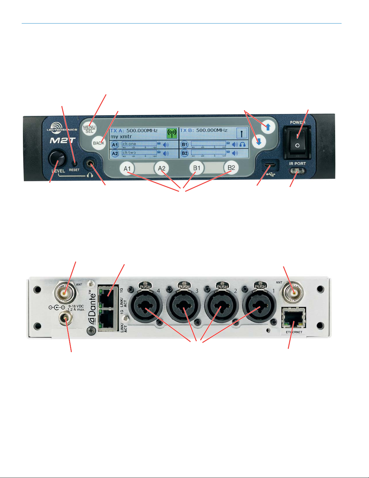
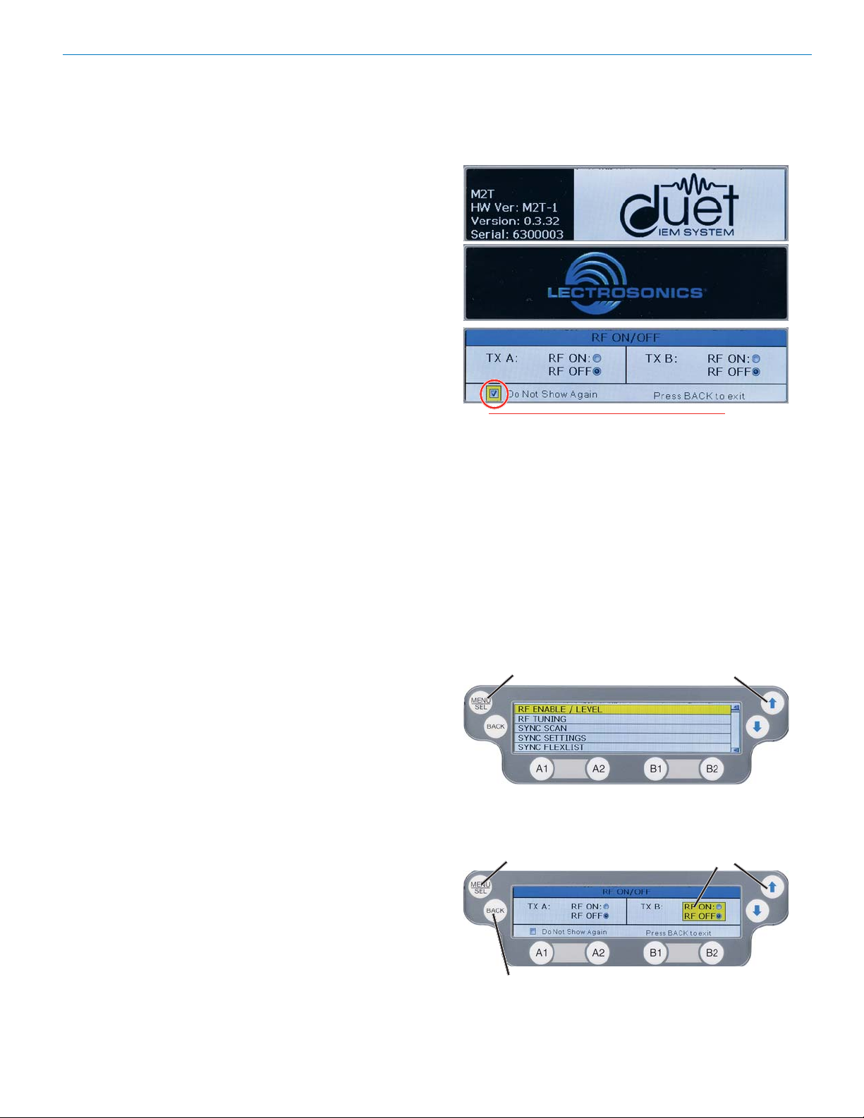
Power Screens
When powering on the M2T, there are three screens
that appear in the following order, Duet, Lectrosonics,
RF On/Off.:
WARNING: If RF ON is selected and the
user chooses to “Do Not Show Again” RF
transmissions will be on when M2T is powered
on and may interfere with frequencies already
in use. This can be reset in the FRONT PANEL
menu.
Navigating the Menus
All Menu setup items are arranged in a vertical list on
the LCD. Press MENU/SEL to enter the menu, then
navigate with the UP and DOWN arrows to highlight
the desired setup item. Refer to the menu map on the
following page.
Press MENU/
SEL to enter
the menu
Press the UP and DOWN arrows
to navigate and highlight the
desired menu item
Rio Rancho, NM
Press MENU/SEL
to enter the setup
of the highlighted
item
Press BACK
to return to
the previous
screen
Press the UP and DOWN arrows
to navigate and highlight the
desired item
5

M2T
LCD Menu Map
RF ENABLE/LEVEL
RF TUNING
SYNC SCAN
SYNC SETTINGS
SYNC FLEXLIST
AUDIO LEVEL/TRIM
AUDIO INPUT TYPE
SEL
SEL
SEL
SEL
SEL
SEL
SEL
RF ENABLE/LEVEL
BACK
BACK
BACK
BACK
BACK
BACK
BACK
SYNC SETTINGS
SYNC FLEXLIST
AUDIO LEVEL/TRIM
AUDIO INPUT TYPE
RF TUNING
SYNC SCAN
Press SEL to
select desired
adjustment step
Press SEL to
select desired
adjustment step
Press SEL to
select desired
function
Press SEL to
select desired
function
Press SEL to
select desired
function
Press SEL to
select desired
channel
Use arrow keys
to select desired
channel
Use arrow keys
to enable or
adjust
Use arrow keys
to select desired
frequency
Use arrow keys
to select desired
sync command
or tune frequency
Use arrow keys
to select desired
sync command
Press SEL to
engage function
Use arrow keys
to adjust setting
Use arrow keys
to select desired
audio setting
AUDIO POLARITY
HEADPHONE
MONITOR
FRONT PANEL
SETUP
NETWORK
SETTINGS
EDIT NAMES
RESTORE
DEFAULTS
ABOUT
SEL
SEL
SEL
SEL
SEL
SEL
SEL
BACK
BACK
BACK
BACK
BACK
BACK
BACK
AUDIO POLARITY
HEADPHONE
CONFIG
FRONT PANEL
SETUP
NETWORK
SETTINGS
EDIT NAMES
RESTORE
DEFAULTS
ABOUT
Press SEL to
select desired
channel
Use arrow keys
to select desired
headphone
output setting
Press SEL to
select desired
function
Press SEL to
select desired
adjustment step
Press SEL to
select desired
function
Use arrow keys
to select yes
or no
No selections available; for
information purposes only
Use arrow keys
to select desired
audio setting
Use arrow keys
to adjust desired
front panel
setting
Use arrow keys
to adjust desired
settings
Use arrow keys
to enter desired
name
Press SEL to
execute
LINKS
6
SEL
BACK
LINKS
No selections available; use phone to scan QR code
for more information
LECTROSONICS, INC.

Digital IEM Transmitter
Menu Item Descriptions
RF Enable/Level
Allows RF transmission to be turned on and off and set
RF levels at 10, 25 or 50 mW.
RF Tuning
Allows manual selection of the operating frequency.
Sync Scan
Receive frequency scan via IR port or tune transmitters
manually.
Sync Settings
Allows sending or retrieving setup data via IR port.
Sync FlexList™
FlexList allows the user to set up a list of profiles, by
name, in the receiver. This allows quick and easily access to listen to any of the mixes on site.
After putting the receiver into Sync Flex mode, choose
the function (add, update) and then use the transmitter
to send the profile over IR.
Screen will alert user if scan is unsuccessful.
Rio Rancho, NM
7

M2T
Audio Level/Trim
Set audio inputs at correct levels.
Easily switch between
channels with A1, A2, B1
or B2 Buttons.
Audio Input Type
Set independent channels to analog or digital (Dante).
NOTE: When selecting a Dante input, user must be
familiar with the Dante Controller from Audinate.
Front Panel Setup
Settings for the LCD brightness can be customized,
front panel lock can be turned on/off and startup RF
state can be selected..
Network Settings
Allows the user to set IP address or other network settings when needed.
NOTE: New network settings require the unit
to reboot to take effect. Making a change and
pressing the BACK key will prompt the user to
Reboot Now, Save and Exit, or Discard and Exit.
Edit Names
Edit names to match talent for easy location in the FlexList or easily identify multiple M2T transmitters in a rack.
• Use UP and DOWN Arrows to select letters and
MENU/SEL to set and move cursor.
Audio Polarity
Select normal or inverted polarity for each
audio channel.
Headphone Monitor
The headphone source can be selected here or on the
front panel, using the A1, A2, B1 or B2 Buttons.
Restore Defaults
Returns all settings to the factory defaults.
About
Displays general information about the M2T,
including serial number, and hardware, FPGA and
microcontroller versions.
8
LECTROSONICS, INC.

Digital IEM Transmitter
Links
QR codes with links to the Lectrosonics website, the
M2T User Manual online and YouTube video tutorials.
System Setup Procedures
Summary of Steps
1) Connect power using supplied DCR15/4AU power
supply.
2) Power receiver and scan RF spectrum on site.
3) Sync Scan to transfer information from receiver
to transmitter.
4) Tune transmitter to unoccupied channels in scan.
5) Sync receiver.
6) Turn on transmitter RF.
7) Send audio sources to transmitter.
Rio Rancho, NM
9

M2T
Accessories
DCR15/A4U
SNA600 Antennas
Replacement Rack Mount Hardware
10
LECTROSONICS, INC.

Specifications and Features
Specifications
RF Power Output:
• Two carriers; two audio channels each
• Power adjustable on each carrier to
10, 25 or 50 mW
Antenna Output: 2 x BNC sockets
Operating Frequencies: 470.100 – 607.975 MHz
Frequency Selection Steps: 25 kHz
Frequency Stability: ± 0.002%
Modulation: 8 PSK
Emission Designator: 200KG7E
Spurious Radiation: Compliant with ETSI EN 300 422-1
Equivalent input Noise: –128 dBV
Audio Frequency Response: 20 Hz - 15 kHz
Audio Input: -10 dBV or +4 dBu settings w/ ±5 dB trim
Audio Input Jack: 4 x combo XLR/TRS connectors
Input impedance: Line: 2k Ohm
Dante Connection: 2 x RJ45, 4 audio RX channels, internally routable
Ethernet Connection: RJ45
USB Connection: Micro USB on front panel for firmware updates
IRDA: IR transceiver for sync of receivers
Headphone jack 3.5 mm stereo jack
Power Requirements: 9-18 VDC
Power Consumption: 5 Watts
Dimensions: Height: 1.750 in. / 44.45 mm
Width: 8.375 in. / 212.7 mm
Depth: 7.750 in. / 196.8 m.
Digital IEM Transmitter
Specifications subject to change without notice.
Rio Rancho, NM
11

M2T
Wireless Designer
Software and USB Driver
Windows Installation
Download the Wireless Designer software installer
from the web sites under the SUPPORT tab at:
http://www.lectrosonics.com/US
http://www.lectrosonics.com/europe/
or use the flash drive supplied with the receiver.
These instructions are useful for the first time the software is being installed. Once the software is installed,
updates are available by simply clicking on an item in
the Help Menu. Refer to the help menu for details.
Launch the installer and follow the screen prompts.
The installer includes USB drivers, which only need to
be installed once. By default, the boxes are unchecked
in the installer, because they are not required except
for the very first time the software is installed on the
computer being used.
If it is the first time the software is being installed,
check the appropriate box to install the USB driver for
the receiver model you are connecting.
If the USB driver is installed, the software will communicate with whichever model is connected.
I Agree on the EULA (end user license agreement)
must be checked to continue the installation.
When the installation is complete, the confirmation
screen will appear. Click on Finish to complete the
installation.
12
LECTROSONICS, INC.

Wireless Designer
Software and USB Driver
Software for Mac® OS X Operating Systems
Installation
Using only the Firefox web browser, open Wireless Designer. If the Firefox Silverlight plugin has not been used
before you will be prompted to “Activate Silverlight”
before Wireless Designer loads.
Note: The Apple Safari web browser no longer
suppors installation of Silverlight applications
like Wireless Designer. Existing installations will
continue to work normally, but new installations
must be made using the Mozilla Firefox Browser.
After Wireless Designer loads, right-click on the page
and choose “Install Wireless Designer onto this computer...” from the pop-up menu. A dialog box will open to
confirm, click “Install” to proceed.
A dialog box will open to announce that Wireless Designer has been added to your downloads folder. Click
the “Open Downloads Folder” button and drag Wireless
Designer onto the Dock or into your Applications folder.
Double-click Wireless Designer to launch it. The first
time you launch it you may receive a “Wireless Designer can’t be opened...” warning. If so, click “OK” to
dismiss the warning and perform the following steps
immediately:
Open the Apple “System Preferences” application and
double-click the “Security & Privacy” icon.
Near the bottom of the “Security & Privacy” pane you
should see the message “Wireless Designer was
blocked from opening because it is not from an identified developer.”
Digital IEM Transmitter
Click “Open Anyway”. Another warning dialog box
opens, click “Open” to launch Wireless Designer. This
only needs to be done once, Wireless Designer will
launch normally thereafter.
Note: If Wireless Designer is already installed,
you must uninstall it before attempting to install a
new copy. To do this, launch Wireless Designer,
right-click and choose “Remove this application...”
from the pop-up menu. Drage the Wireless
Designer Dock icon to the desktop to remove it.
Software Installer
Installation oftware supplied on USB drive. Can also be
downloaded from the web site.
WDDISK
Firmware Update
Instructions
Firmware updates are made with a file downloaded
from the web site and a USB connection to the receiver.
Refer to Help in Wireless Designer software for the
procedure.
Rio Rancho, NM
13

M2T
Service and Repair
If your system malfunctions, you should attempt to correct or isolate the trouble before concluding that the equipment
needs repair. Make sure you have followed the setup procedure and operating instructions. Check the interconnecting
cables and then go through the Troubleshooting section in this manual.
We strongly recommend that you do not try to repair the equipment yourself and do not have the local repair shop attempt anything other than the simplest repair. If the repair is more complicated than a broken wire or loose connection,
send the unit to the factory for repair and service. Don’t attempt to adjust any controls inside the units. Once set at the
factory, the various controls and trimmers do not drift with age or vibration and never require readjustment. There are
no adjustments inside that will make a malfunctioning unit start working.
LECTROSONICS’ Service Department is equipped and staffed to quickly repair your equipment. In warranty repairs
are made at no charge in accordance with the terms of the warranty. Out-of-warranty repairs are charged at a modest
flat rate plus parts and shipping. Since it takes almost as much time and effort to determine what is wrong as it does
to make the repair, there is a charge for an exact quotation. We will be happy to quote approximate charges by phone
for out-of-warranty repairs.
Returning Units for Repair
For timely service, please follow the steps below:
A. DO NOT return equipment to the factory for repair without first contacting us by email or by phone. We need
to know the nature of the problem, the model number and the serial number of the equipment. We also need a
phone number where you can be reached 8 A.M. to 4 P.M. (U.S. Mountain Standard Time).
B. After receiving your request, we will issue you a return authorization number (R.A.). This number will help speed
your repair through our receiving and repair departments. The return authorization number must be clearly shown
on the outside of the shipping container.
C. Pack the equipment carefully and ship to us, shipping costs prepaid. If necessary, we can provide you with the
proper packing materials. UPS is usually the best way to ship the units. Heavy units should be “double-boxed” for
safe transport.
D. We also strongly recommend that you insure the equipment, since we cannot be responsible for loss of or dam-
age to equipment that you ship. Of course, we insure the equipment when we ship it back to you.
Lectrosonics USA:
Mailing address: Shipping address: Telephone:
Lectrosonics, Inc. Lectrosonics, Inc. (505) 892-4501
PO Box 15900 561 Laser Rd. NE, Suite 102 (800) 821-1121 Toll-free
Rio Rancho, NM 87174 Rio Rancho, NM 87124 (505) 892-6243 Fax
USA USA
Web: E-mail:
www.lectrosonics.com sales@lectrosonics.com
service.repair@lectrosonics.com
Lectrosonics Canada:
Mailing Address: Telephone: E-mail:
720 Spadina Avenue, (416) 596-2202 Sales: colinb@lectrosonics.com
Suite 600 (877) 753-2876 Toll-free Service: joeb@lectrosonics.com
Toronto, Ontario M5S 2T9 (877-7LECTRO)
(416) 596-6648 Fax
14
LECTROSONICS, INC.

Digital IEM Transmitter
ISEDC Notices:
Per RSS-210
This device operates on a no-protection no-interference basis. Should the user seek to obtain
protection from other radio services operating in the same TV bands, a radio licence is required.
Please consult Industry Canada’s document CPC-2-1-28, Optional Licensing for Low-Power
Radio Apparatus in the TV Bands, for details.
Ce dispositif fonctionne selon un régime de non-brouillage et de non-protection. Si l’utilisateur
devait chercher à obtenir une certaine protection contre d’autres services radio fonctionnant
dans les mêmes bandes de télévision, une licence radio serait requise. Pour en savoir plus,
veuillez consulter le document CPC-2-1-28 d’Industrie Canada intitulé, Délivrance de licences
sur une base volontaire pour les appareils radio de faible puissance exempts de licence et exploités dans les bandes de télévision.
Per RSS-Gen
This device complies with Industry Canada’s license-exempt RSSs. Operation is subject to the
following two conditions:
1) This device may not cause interference
2) This device must accept any interference, including interference that may cause undesired
operation of the device.
Le présent appareil est conforme aux CNR d’Industrie Canada applicables aux appareils radio
ex¬empts de licence. L’exploitation est autorisée aux deux conditions suivantes :
1) l’appareil ne doit pas produire de brouillage;
2) l’appareil doit accepter tout brouillage radioélectrique subi, même si le brouillage est suscep
tible d’en compromettre le fonctionnement.
Rio Rancho, NM
15

LIMITED ONE YEAR WARRANTY
The equipment is warranted for one year from date of purchase against defects in
materials or workmanship provided it was purchased from an authorized dealer. This
warranty does not cover equipment which has been abused or damaged by careless
handling or shipping. This warranty does not apply to used or demonstrator equipment.
Should any defect develop, Lectrosonics, Inc. will, at our option, repair or replace any
defective parts without charge for either parts or labor. If Lectrosonics, Inc. cannot
correct the defect in your equipment, it will be replaced at no charge with a similar new
item. Lectrosonics, Inc. will pay for the cost of returning your equipment to you.
This warranty appli
dealer, shipping costs prepaid, within one year from the date of purchase.
This Limited Warranty is governed by the laws of the State of New Mexico. It states the
entire liablility of Lectrosonics Inc. and the entire remedy of the purchaser for any
breach of warranty as outlined above. NEITHER LECTROSONICS, INC. NOR
ANYONE INVOLVED IN THE PRODUCTION OR DELIVERY OF THE EQUIPMENT
SHALL BE LIABLE FOR ANY INDIRECT, SPECIAL, PUNITIVE, CONSEQUENTIAL,
OR INCIDENTAL DAMAGES ARISING OUT OF THE USE OR INABILITY TO USE
THIS EQUIPMENT EVEN IF LECTROSONICS, INC. HAS BEEN ADVISED OF THE
POSSIBILITY OF SUCH DAMAGES. IN NO EVENT SHALL THE LIABILITY OF
LECTROSONICS, INC. EXCEED THE PURCHASE PRICE OF ANY DEFECTIVE
EQUIPMENT.
This warranty gives you specific legal rights. You may have additional legal rights which
vary from state to state.
es only to items returned to Lectrosonics, Inc. or an authorized
581 Laser Road NE • Rio Rancho, NM 87124 USA • www.lectrosonics.com
(505) 892-4501 • (800) 821-1121 • fax (505) 892-6243 • sales@lectrosonics.co
m
10 August 2017
 Loading...