

Page 1

M2R
Digital IEM Receiver
INSTRUCTION MANUAL
Fill in for your records:
Quick Start Summary
1) Install receiver batteries (pg. 6).
2) Power unit on with On/Off and Volume knob (pg. 4).
3) Scan for an available frequency (pg.9).
4) Sync the receiver with a transmitter (pg. 10).
5) Enable RF in transmitter (see transmitter manual).
6) Send audio (pg. 9).
Serial Number:
Purchase Date:
Rio Rancho, NM, USA
www.lectrosonics.com
Page 2

M2R
Table of Contents
Quick Start Summary ............................................................................................................................................................................1
M2R Digital IEM Receiver ...................................................................................................................................................................3
FlexList™ ..............................................................................................................................................................................................3
RF Front-End with Tracking Filter ..........................................................................................................................................................3
Panels and Features ...............................................................................................................................................................................4
Battery Status LED ...............................................................................................................................................................................5
RF Link LED ..........................................................................................................................................................................................5
On/Off and Volume Knob ......................................................................................................................................................................5
IR (infrared) Port ...................................................................................................................................................................................5
USB Port ...............................................................................................................................................................................................5
Battery Compartment............................................................................................................................................................................ 5
Keypad and LCD Interface ....................................................................................................................................................................5
Installing Batteries .................................................................................................................................................................................6
LCD Main Window ................................................................................................................................................................................6
LCD Menu Map ........................................................................................................................................................................................8
Menu Item Descriptions .........................................................................................................................................................................9
System Setup Procedures ...................................................................................................................................................................12
Accessories ..........................................................................................................................................................................................13
Specifications .......................................................................................................................................................................................13
Wireless Designer Software and USB Driver .....................................................................................................................................14
Wireless Designer Software and USB Driver .....................................................................................................................................15
Software Installer ................................................................................................................................................................................15
Firmware Update Instructions .............................................................................................................................................................15
Service and Repair ...............................................................................................................................................................................17
Returning Units for Repair ..................................................................................................................................................................17
NOTE: This equipment has been tested and found to comply with the limits for a Class B digital device, pursuant to
part 15 of the FCC Rules. These limits are designed to provide reasonable protection against harmful interference in
a residential installation. This equipment generates, uses and can radiate radio frequency energy and, if not installed
and used in accordance with the instructions, my cause harmful interference to radio communications. However,
there is no guarantee that interference will not occur in a particular installation. If this equipment does cause harmful
interference to radio or television reception, which can be determined by turning the equipment off and on, the user is
encouraged to try to correct the interference by one or more of the following measures:
• Reorient or relocate the receiving antenna.
• Increase the separation between the equipment and receiver.
• Connect the equipment into an outlet on a circuit different from that to which the receiver is connected.
• Consult the dealer or an experienced radio/TV technician for help.
2
LECTROSONICS, INC.
Page 3

Digital IEM Receiver
M2R Digital IEM Receiver
The M2R Digital IEM Receiver is a compact, rugged
body-worn unit providing studio-grade sound quality
for performers or any professionals needing to monitor
detailed audio wirelessly. The M2R employs advanced
antenna diversity switching during digital packet
headers for seamless audio. The receiver covers UHF
frequencies from 470.100 to 614.375 MHz and uses
digital modulation. The 24-bit digital audio stream
guarantees high resolution sound quality with wide
dynamic range, low noise floor, and solid stereo image.
The headphone jack is fed from a high-quality stereo
amplifier with 250 mW available to drive even inefficient headphones or earphones to sufficient levels for
stage performance or other noisy environments. The
receiver can select from stereo, mono from left or right
channels only, or mono from both channels, giving
the unit flexibility in terms of application as an IEM or
IFB receiver. An intuitive interface and high resolution,
color LCD on the unit provide performing artists and
audio professionals alike with a comfortable and confident user experience.
The M2R also employs 2-way IR sync, so can data
from the receiver can be sent to a transmitter and
thus onto Wireless Designer™ Software, via USB or
Ethernet. This way, frequency planning and coordination can be done quickly and confidently with on-site
RF information.
FlexList™
Additionally, the M2R includes a FlexList™ mode,
where up to 16 mixes can be accessed by name. This
feature enables a monitor engineer to quickly find and
listen to any of the performer’s mixes on the stage.
A FlexList mix is a profile of a performer’s personal
transmitter. The mix includes the performer’s name
(or whatever name the user chooses for that unit),
frequency, mixer settings and limiter settings. The mix
is easily shared via the M2R IR port, added to the list
of 16 mixes and stored until cleared by the user. The
M2R allows the user to toggle between the mixes,
making troubleshooting issues easy and efficient.
RF Front-End with Tracking Filter
A wide tuning range is helpful in finding clear frequencies for operation, however, it also allows a greater
range of interfering frequencies to enter the receiver.
The UHF frequency band, where almost all wireless
microphone systems operate, is heavily populated by
high power TV transmissions. The TV signals are immensely more powerful than a wireless microphone or
IEM transmitter signal and will enter the receiver even
when they are on significantly different frequencies
than the wireless system. This powerful energy appears as noise to the receiver, and has the same effect
as the noise that occurs with extreme operating range
of the wireless system (noise bursts and dropouts). To
alleviate this interference, front-end filters are needed
in the receiver to suppress RF energy below and
above the operating frequency.
The M2R receiver employs a selective frequency,
tracking filter in the front-end section (the first circuit
stage following the antenna). As the operating frequency is changed, the filters re-tune into six different
“zones” depending on the selected carrier frequency.
BLOCK
470 MHz
BLOCK
BLOCK
In the front-end circuitry, a tuned filter is followed by
an amplifier and then another filter to provide the selectivity needed to suppress interference, yet provide a
wide tuning range and retain the sensitivity needed for
extended operating range.
BLOCK
BLOCK
BLOCK
614 MHz
Rio Rancho, NM
3
Page 4
M2R
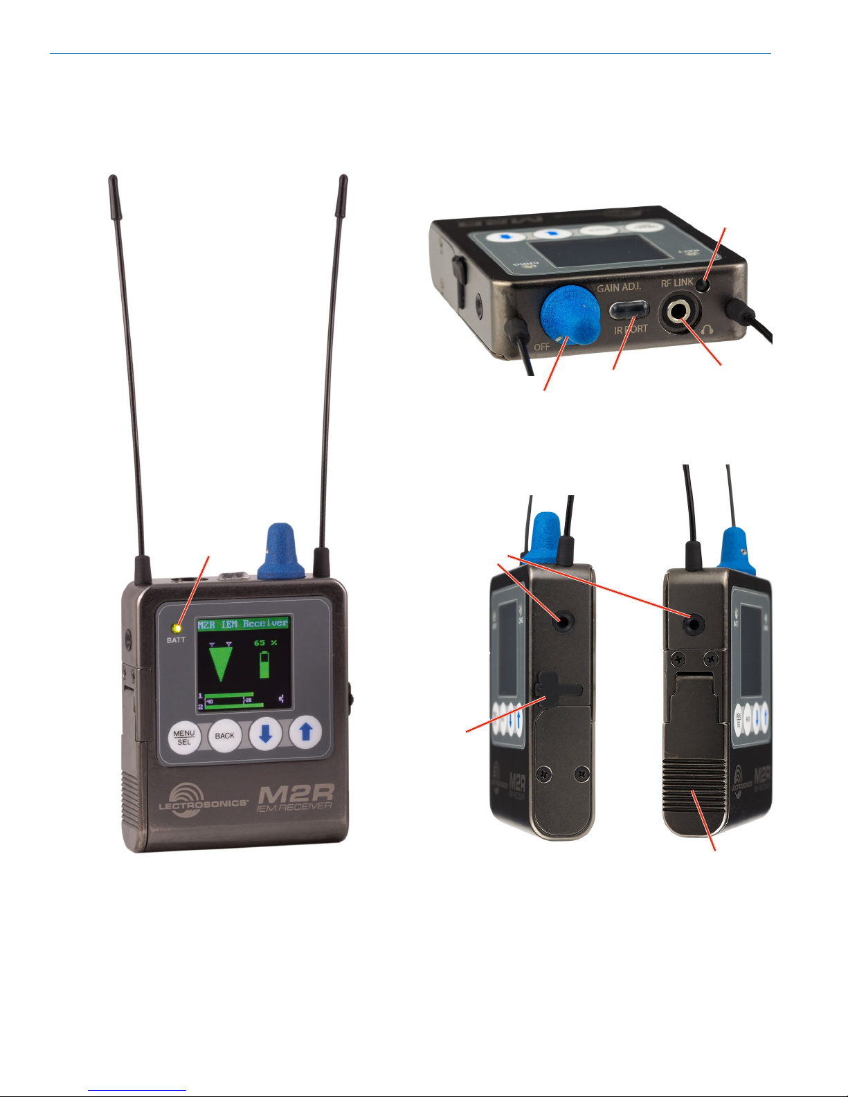
Panels and Features
RF Link LED
Battery status
LED
Belt clip
mounting
sockets
USB
port
On/Off and
volume knob
IR (infrared)
port
Headphone
output
4
Battery compartment
door
LECTROSONICS, INC.
Page 5
Digital IEM Receiver
Battery Status LED
When the battery status LED on the keypad glows
green the batteries are good. The color changes to red
at a midpoint during the runtime. When the LED begins
to blink red, only a few minutes remain.
The exact point at which the LED turns red will vary
with battery brand and condition, temperature and
power consumption. The LED is intended to simply
catch your attention, not to be an exact indicator of
remaining time.
A weak battery will sometimes cause the LED to glow
green immediately after the transmitter is turned on,
but it will soon discharge to the point where the LED
will turn red or the unit will turn off completely.
RF Link LED
When a valid RF signal from a transmitter is received,
this LED will light up blue.
On/Off and Volume Knob
Turns unit on or off and controls headphone audio
level.
IR (infrared) Port
Settings, including frequency, name, limiter, mix mode,
etc. can be transferred between transmitter and receiver. FlexList profiles can be gathered by the receiver. Frequency scan information can be sent from the
receiver to the transmitter and into Wireless Designer
software for coordination purposes.
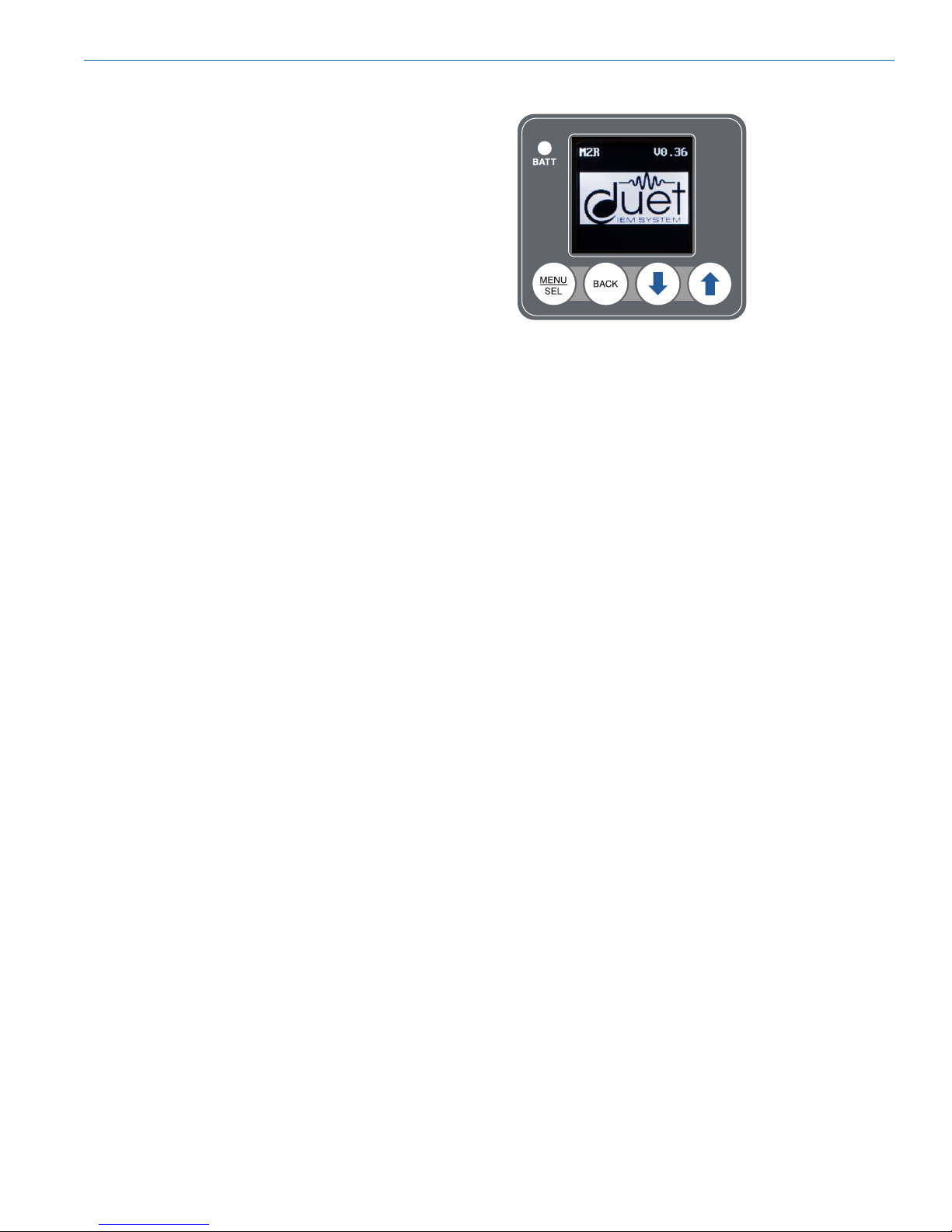
Keypad and LCD Interface
MENU/SEL Button
Pressing this button enters the menu and selects
menu items to enter the setup screens.
BACK Button
Pressing this button returns to the previous menu or
screen.
Arrow Buttons
Used to navigate the menus.
Headphone Output
A recessed, high duty cycle 3.55 mm stereo jack is
provided for standard headpohnes and earphones.
USB Port
Firmware updates via Wireless Designer are made
easy with the USB port on the side panel.
Battery Compartment
Two AA batteries are installed as marked on the rear
panel of the receiver. The battery door is hinged and
remains attached to the housing.
Rio Rancho, NM
5
Page 6

M2R
Installing Batteries
Power is provided by two AA batteries. The batteries
are connected in series by a plate in the battery door.
Slide the battery
door outward to
open it
Polarity is marked on the rear panel.
Polarity markings
LCD Main Window
Receiver
Name
RF Level
RF level
The triangle graphic corresponds to the scale on the
left side of the display. The scale indicates the incoming signal strength in microvolts, from 1 uV at the bottom to 1,000 uV (1 millivolt) at the top.
Diversity activity
The two antenna icons will alternately light up depending on which one is receiving the stronger signal.
Battery Life Indicator
The battery life icon is an approximate indicator of the
remaining battery life. For the most accurate indication,
the user should select “Battery Type” in the menu and
select Alkaline or Lithium.
Audio level
This bar graph indicates the level of the audio entering
the transmitter. The “0” refers to the level reference, as
chosen in the transmitter, i.e. either +4 dBu or -10 dBV.
Diversity
Activity
Battery life
indicator
Audio Level
6
LECTROSONICS, INC.
Page 7

Navigating the Menus
From the Main Window, press MENU/SEL to enter the
menu, then navigate with the UP and DOWN arrows to
highlight the desired setup item. Press MENU/SEL to
enter the setup screen for that item. Refer to the menu
map on the following page.
Press MENU/
SEL to enter
the menu
Digital IEM Receiver
Submenus and screens for
the selected item
Press MENU/
SEL to
enter the
setup of the
highlighted
item
Press BACK to
return to the
previous screen
Press the UP and DOWN
arrows to navigate and
highlight the desired
menu item
Decision
prompts
to save
settings
Press MENU/
SEL to
select the
highlighted
item
Press the UP and DOWN
arrows to navigate and
highlight the desired
selection
Rio Rancho, NM
7
Page 8

M2R
LCD Menu Map
The menus presented on the LCD are arranged in a
straightforward manner, with those that are likely to be
used more often located at the top of the tree.
Scan
FlexList
Frequency
Vol/Bal
Mixer
Limiter
HF Boost
SEL
SEL
SEL
SEL
SEL
SEL
SEL
BACK
BACK
BACK
BACK
BACK
BACK
BACK
wait
for
scan
FlexList
Frequency
Volume 0
Balance CNTR
Mixer
Limiter
HF Boost
SEL
pause
scan
zoom
scan
Listen
Add
Update
548.900
900
Mono Ch1
Stereo
SwapLR
Gain
Threshold
Boost
Corner
Use arrow keys
to tune to desired
frequency
Delete
Clear All
Press SEL to
select desired
adjustment step
Use arrow keys
to select desired
levels
Custom
Mono 1+2
Mono CH2
+9
+0
+0
5k
Press SEL to
choose parameter
Press SEL to
choose parameter
Press BACK to
BACK
keep or revert back
to old frequency
Use arrow keys to
select option
Use arrow keys
to select desired
frequency
Use arrow keys to
select mixer option
Keep scan freq?
Press BACK to
BACK
return to normal
operation
Use arrow keys to
adjust parameter
Use arrow keys to
adjust parameter
Keep
Revert
Meter Mode
Clear Scan Data
Backlight
Battery Type
Compat. Mode
Lock/Unlock
About M2R
SEL
SEL
SEL
SEL
SEL
SEL
SEL
BACK
BACK
BACK
BACK
BACK
BACK
BACK
Meter Mode
Clear Scan Data?
Backlight
Battery Type
Compat. Mode
Lock Settings?
About M2R
Pre-Mix
Post-Mix
No
Yes
Always On
30 Seconds
5 Minutes
Alkaline
Lithium
Duet IEM
IFB (FM)
Unlocked
Locked
No selections available;
for information
purposes only
Use arrow keys to select Pre- or
Post-Mix audio metering
Use arrow keys to accept or
reject clearing scan data
Use arrow keys to select
backlight duration
Use arrow keys to select
battery type for accurate
battery level indication
Use arrow keys to select
the desired mode
Use arrow keys to lock or
unlock front panel settings
Press SEL
to complete
8
LECTROSONICS, INC.
Page 9

Menu Item Descriptions
Scan
Use the scan function to identify a usable frequency.
The area in red has not been scanned. Allow the scan
to continue until the entire band has been scanned.
Once a full cycle has been completed, press MENU/
SELECT again to pause the scan.
Digital IEM Receiver
When a usable frequency has been selected, press
the BACK button for the option to keep your newly selected frequency or to revert to where it was set before
the scan.
Use the UP and DOWN arrows to roughly tune the
receiver by moving the cursor to an open spot. Press
MENU/SELECT to zoom in for fine tuning.
Use the UP
and DOWN
arrow keys
to move the
cursor to open
frequency
To capture this scan info in the transmitter and thus
make it available to wireless designer, use the SYNC
SCAN menu funtion in the M2T Transmitter.
Rio Rancho, NM
9
Page 10

M2R
Flex List
FlexList allows the user to set up a list of profiles, by
name, to quickly and easily listen to any of the mixes
on site individually.
Listen - choose a mix from the list and hear what is
transmitting
Add - add a mix to the available Flex List
(action performed via the IR port)
Clear All - Remove all mixes from the Flex List
Frequency
Allows manual selection of the operating frequency in
MHz and KHz, tunable in 25 kHz steps.
Update - Update settings in a mix (frequency, etc.).
Action performed via the IR port.
Delete - Remove a mix from the Flex List
Vol/Bal
Displays the volume, from 0 to 100, and adjusts the
balance to left, right or center.
Mixer Mode
This screen allows you to choose a stereo mix, mono
mix from either audio channel 1, channel 2 or both, or
custom, allowing for varied width of the signal and how
much level from each channel.
The available modes are:
• Stereo
• SwapLR
• Custom
• Mono 1&2
• Mono Ch 2
10
LECTROSONICS, INC.
Page 11

Digital IEM Receiver
Limiter
Limiter function allows the user to set volume and
dynamic range for headphone use.
Gain - The default setting (0) is linear, but if additonal
volume is needed, use the UP and DOWN arrows to
adjust the audio by up to +18 dB in 3dB steps.
WARNING: Increasing the Gain can make
headphone volume excessively loud. Use
caution when setting and using.
Threshold - Use the UP and DOWN arrows to adjust
the threshold for limiter engagement in 3dB increments.
NOTE: A common setup to play loud and bring
softer dynamics up a bit is to set the pregain at
+6 or +9 dB and set the threshold for -3 or -6dB.
HF Boost
Adjusts loudness of higher
frequencies in the audio
output as preferred by the
listener. Corner frequencies
of 5 KHz or 7 KHz can be
selected and boosted.
Clear Scan Data
Erases scan results from
memory.
Backlight
Selects the length of time
the backlight on the LCD
remain turned on: Always
on, 30 seconds, and
5 minutes.
Battery Type
Selects the type of battery
being used: Alkaline
or Lithium so the remaining
battery meter on the home
screen is as accurate as
possible.
Meter Mode
Changes the appearance of
the audio level indicator on
the main window; can show
either pre- or post mix audio
levels.
Rio Rancho, NM
Lock/Unlock
The front panel controls can
be locked to prevent unwanted changes.
About M2R
Displays general information
about the M2R, including
serial number and the
versions for both FPGA and
main firmware running in
the receiver.
11
Page 12

M2R
Default
Menu Item Setting
Flexlist Cleared
Vol/Bal Centered
Mixer Mode Stereo
Limiter Pregain 0
HF Boost 0
Meter Mode Post-Mix
Backlight Always On
Battery Type Lithium
Settings Unlock
Receiver
Name
Frequency 512.00
M2R IEM Receiver
Returns all settings to the
factory defaults as shown in
the table below.
System Setup Procedures
Summary of Steps
1) Install receiver batteries.
2) Power unit on with On/Off and Volume knob.
3) Scan for an available frequency.
4) Sync the receiver with a transmitter.
5) Enable RF in transmitter.
6) Send audio.
1 and 2) Install Receiver Batteries and Power On
Install the batteries according to the diagram marked
on the back of the housing, power on the M2R and
select the battery type in the menu. Check the BATT
LED on the control panel to verify adequate power is
present - the LED should glow green.
3) Scan For An Available Frequency
Navigate to Scan in the LCD menu. The first scan
should be allowed to run completely. Once a full cycle
has been completed, press MENU/SELECT again to
pause the scan. Use the UP and DOWN arrows to
roughly tune the receiver by moving the cursor to an
open spot. Press MENU/SELECT to zoom in for fine
tuning. When an open frequency has been selected,
press the BACK button for the option to keep your
newly selected frequency or to revert to where it was
set before the scan (refer to page 9 for details).
4) Sync With A Transmitter
Use transmitter “get settings” menu to transfer frequency or other information.
5) Enable RF in Transmitter
From the transmitter menu, enable RF and select
appropriate RF power level. The blue “link” LED on the
top of the receiver should light up, indicating an
RF link.
6) Send Audio
Send an audio signal to the transmitter and the receiver audio meters should respond. Plug in headphones
or earphones. (Be sure to start with the receiver volume knob at minimum!)
12
LECTROSONICS, INC.
Page 13

Digital IEM Receiver
Accessories
26895
Wire belt clip.
21926
USB cable for firmware updates
Specifications
Operating Spectrum: 470.100 - 614.375 MHz
Modulation Type: 8PSK with Forward Error
CorrectionOccupied
Latency:
Digital Source: 1.0 ms over
Dante Network
Analog Source: <1.4 ms
Audio Performance:
Frequency Response: 20Hz - 15 KHz, - 3dB
THD+N: 0.15% (1kHz @ -10 dBFS)
Dynamic Range: >95 dB weighted
Adjacent Channel Isolation >85dB
Diversity Type: Switched antenna phase,
during packet headers
Audio Output: 3.5 mm stereo jack
Power requirements: 2 x AA batteries (3.0V)
Battery life: 7 hours; (2) Lithium AA
Power consumption: 1 W
Dimensions: Height: 3.0 in. / 120 mm.
(with knob)
Width: 2.375 in. /
60.325 mm.
Depth: .625 in. /
15.875 mm.
Weight: 9.14 ounces / 259 grams
(with batteries)
Specifications subject to change without notice.
Rio Rancho, NM
13
Page 14

M2R
Wireless Designer
Software and USB Driver
Windows Installation
Download the Wireless Designer software installer
from the web sites under the SUPPORT tab at:
http://www.lectrosonics.com/US
http://www.lectrosonics.com/europe/
or use the flash drive supplied with the receiver.
These instructions are useful for the first time the software is being installed. Once the software is installed,
updates are available by simply clicking on an item in
the Help Menu. Refer to the help menu for details.
Launch the installer and follow the screen prompts.
The installer includes USB drivers, which only need to
be installed once. By default, the boxes are unchecked
in the installer, because they are not required except
for the very first time the software is installed on the
computer being used.
If it is the first time the software is being installed,
check the appropriate box to install the USB driver for
the receiver model you are connecting.
If the USB driver is installed, the software will communicate with whichever model is connected.
I Agree on the EULA (end user license agreement)
must be checked to continue the installation.
When the installation is complete, the confirmation
screen will appear. Click on Finish to complete the
installation.
14
LECTROSONICS, INC.
Page 15

Wireless Designer
Software and USB Driver
Software for Mac® OS X Operating Systems
Installation
Using only the Firefox web browser, open Wireless
Designer. If the Firefox Silverlight plugin has not been
used before you will be prompted to “Activate Silverlight” before Wireless Designer loads.
Note: The Apple Safari web browser no longer
suppors installation of Silverlight applications
like Wireless Designer. Existing installations will
continue to work normally, but new installations
must be made using the Mozilla Firefox
Browser.
After Wireless Designer loads, right-click on the page
and choose “Install Wireless Designer onto this computer...” from the pop-up menu. A dialog box will open
to confirm, click “Install” to proceed.
A dialog box will open to announce that Wireless Designer has been added to your downloads folder. Click
the “Open Downloads Folder” button and drag Wireless
Designer onto the Dock or into your Applications folder.
Double-click Wireless Designer to launch it. The first
time you launch it you may receive a “Wireless Designer can’t be opened...” warning. If so, click “OK” to
dismiss the warning and perform the following steps
immediately:
Open the Apple “System Preferences” application and
double-click the “Security & Privacy” icon.
Near the bottom of the “Security & Privacy” pane you
should see the message “Wireless Designer was
blocked from opening because it is not from an identified developer.”
Digital IEM Receiver
Click “Open Anyway”. Another warning dialog box
opens, click “Open” to launch Wireless Designer. This
only needs to be done once, Wireless Designer will
launch normally thereafter.
Note: If Wireless Designer is already installed,
you must uninstall it before attempting to install a
new copy. To do this, launch Wireless Designer,
right-click and choose “Remove this application...”
from the pop-up menu. Drage the Wireless
Designer Dock icon to the desktop to remove it.
Software Installer
Installation oftware supplied on USB drive. Can also
be downloaded from the web site.
WDDISK
Firmware Update
Instructions
Firmware updates are made with a file downloaded
from the web site and a USB connection to the receiver.
Refer to Help in Wireless Designer software for the
procedure.
Rio Rancho, NM
15
Page 16

M2R
16
LECTROSONICS, INC.
Page 17

Digital IEM Receiver
Service and Repair
If your system malfunctions, you should attempt to correct or isolate the trouble before concluding that the equipment needs repair. Make sure you have followed the setup procedure and operating instructions. Check the interconnecting cables.
We strongly recommend that you do not try to repair the equipment yourself and do not have the local repair shop
attempt anything other than the simplest repair. If the repair is more complicated than a broken wire or loose connection, send the unit to the factory for repair and service. Don’t attempt to adjust any controls inside the units.
Once set at the factory, the various controls and trimmers do not drift with age or vibration and never require readjustment. There are no adjustments inside that will make a malfunctioning unit start working.
LECTROSONICS’ Service Department is equipped and staffed to quickly repair your equipment. In warranty repairs
are made at no charge in accordance with the terms of the warranty. Out-of-warranty repairs are charged at a modest flat rate plus parts and shipping. Since it takes almost as much time and effort to determine what is wrong as it
does to make the repair, there is a charge for an exact quotation. We will be happy to quote approximate charges by
phone for out-of-warranty repairs.
Returning Units for Repair
For timely service, please follow the steps below:
A. DO NOT return equipment to the factory for repair without first contacting us by e-mail or by phone. We need
to know the nature of the problem, the model number and the serial number of the equipment. We also need a
phone number where you can be reached 8 A.M. to 4 P.M. (U.S. Mountain Standard Time).
B. After receiving your request, we will issue you a return authorization number (R.A.). This number will help
speed your repair through our receiving and repair departments. The return authorization number must be
clearly shown on the outside of the shipping container.
C. Pack the equipment carefully and ship to us, shipping costs prepaid. If necessary, we can provide you with
the proper packing materials. UPS or FEDEX is usually the best way to ship the units. Heavy units should be
“double-boxed” for safe transport.
D. We also strongly recommend that you insure the equipment, since we cannot be responsible for loss of or dam-
age to equipment that you ship. Of course, we insure the equipment when we ship it back to you.
Lectrosonics USA:
Mailing address: Shipping address: Telephone:
Lectrosonics, Inc. Lectrosonics, Inc. +1 (505) 892-4501
PO Box 15900 561 Laser Rd., Suite 102 (800) 821-1121 Toll-free US and Canada
Rio Rancho, NM 87174 Rio Rancho, NM 87124 Fax +1 (505) 892-6243
USA USA
Web: E-mail:
www.lectrosonics.com service.repair@lectrosonics.com
sales@lectrosonics.com
Lectrosonics Canada:
Mailing Address: Telephone: E-mail:
720 Spadina Avenue, +1 (416) 596-2202 Sales: colinb@lectrosonics.com
Suite 600 (877) 753-2876 Toll-free Canada Service: joeb@lectrosonics.com
Toronto, Ontario M5S 2T9 (877) 7LECTRO
Fax (416) 596-6648
Rio Rancho, NM
17
Page 18

LIMITED ONE YEAR WARRANTY
The equipment is warranted for one year from date of purchase against defects in
materials or workmanship provided it was purchased from an authorized dealer. This
warranty does not cover equipment which has been abused or damaged by careless
handling or shipping. This warranty does not apply to used or demonstrator equipment.
Should any defect develop, Lectrosonics, Inc. will, at our option, repair or replace any
defective parts without charge for either parts or labor. If Lectrosonics, Inc. cannot
correct the defect in your equipment, it will be replaced at no charge with a similar new
item. Lectrosonics, Inc. will pay for the cost of returning your equipment to you.
This warranty applies only to items returned to Lectrosonics, Inc. or an authorized
dealer, shipping costs prepaid, within one year from the date of purchase.
This Limited Warranty is governed by the laws of the State of New Mexico. It states the
entire liablility of Lectrosonics Inc. and the entire remedy of the purchaser for any
breach of warranty as outlined above. NEITHER LECTROSONICS, INC. NOR
ANYONE INVOLVED IN THE PRODUCTION OR DELIVERY OF THE EQUIPMENT
SHALL BE LIABLE FOR ANY INDIRECT, SPECIAL, PUNITIVE, CONSEQUENTIAL,
OR INCIDENTAL DAMAGES ARISING OUT OF THE USE OR INABILITY TO USE
THIS EQUIPMENT EVEN IF LECTROSONICS, INC. HAS BEEN ADVISED OF THE
POSSIBILITY OF SUCH DAMAGES. IN NO EVENT SHALL THE LIABILITY OF
LECTROSONICS, INC. EXCEED THE PURCHASE PRICE OF ANY DEFECTIVE
EQUIPMENT.
This warranty gives you specific legal rights. You may have additional legal rights which
vary from state to state.
581 Laser Road NE • Rio Rancho, NM 87124 USA • www.lectrosonics.com
+1(505) 892-4501 • fax +1(505) 892-6243 • (800) 821-1121 US and Canada • sales@lectrosonics.com
15 December 2017
 Loading...