

Page 1

M185
BELT-PACK TRANSMITTER
OPERATING INSTRUCTIONS
and trouble-shooting guide
LECTROSONICS, INC.
Rio Rancho, NM
Page 2

INTRODUCTION
Thank you for selecting the Lectrosonics M185 transmitter. This transmitter represents over 70 years of
combined experience in the design of RF devices and sets new standards for operational convenience,
flexibility and mechanical ruggedness. The M185 transmitter features all metal construction and
operates on high band frequencies from 150mHz to 216mHz. The M185 was designed primarily for
"belt-worn" applications, however it works equally well for other applications and with virtually any
mounting configuration.
The M185 uses the microphone cord as the antenna, eliminating an unsightly "dangling wire". This
transmitter may be used with a wide variety of audio sources. The multi-pin input jack allows the use of
"phantom powered" lavalier microphones with either positive or negative bias voltages. The M185 will
also match low impedance dynamic microphones and high impedance inputs such as musical
instruments or tape decks.
Only the M185 transmitter is covered in this manual. Receivers are described in separate manuals.
The M185 operates with any Lectrosonics 185 or 170 Series VHF receiver. A matched
transmitter/receiver combination makes up a wireless "system".
TABLE OF CONTENTS
INTRODUCTION .......................................... 1
GENERAL TECHNICAL DESCRIPTION .......................... 2
CONTROLS AND FUNCTIONS ................................ 3
BATTERY REPLACEMENT ................................... 5
OPERATING INSTRUCTIONS ................................. 6
M185 INPUT JACK WIRING .................................. 7
TROUBLESHOOTING ....................................... 8
SPECIFICATIONS AND FEATURES ............................ 9
SERVICE AND REPAIR ..................................... 10
RETURNING UNITS FOR REPAIR ............................. 10
WARRANTY ........................................ Back cover
The M185 transmitter is FCC type accepted under the following Parts:
Part 90 (169-172 mHz)
Part 74 (174-216 mHz)
1
Page 3
GENERAL TECHNICAL DESCRIPTION
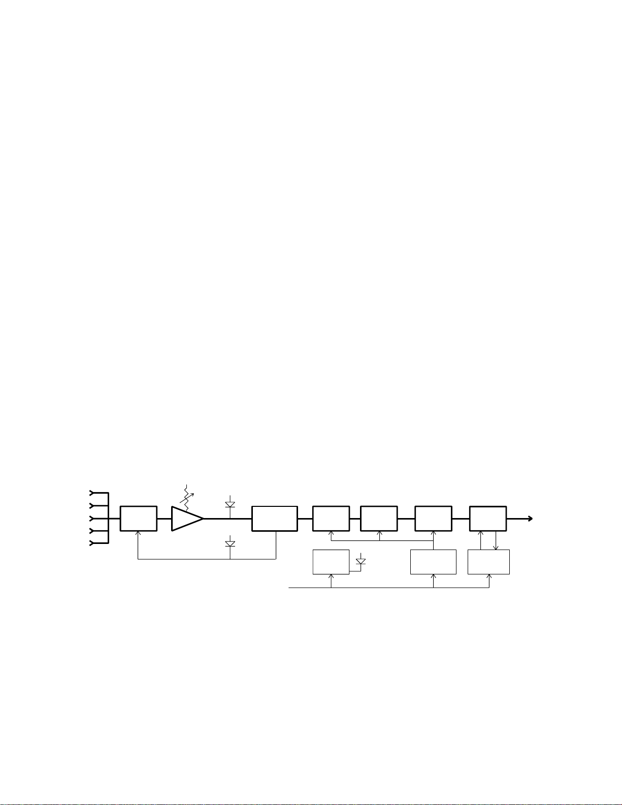
The M185 transmitter is comprised of four major functional subsystems: the input compressor, the mic
preamp/gain control, the compandor, and the RF transmitter (see block diagram below).
The input compressor is a low distortion shunt FET compressor operating before the mic preamp.
Control signals for the compressor are derived after the mic preamp to eliminate any possibility of
overload under any signal condition up to a maximum of 30 Volts input at the pin 5 (line level) input
tap. The range of limiting action before distortion occurs is 20 dB. Audio signal level and compressor
action are indicated by two LEDs on the control panel.
The mic preamp is an ultra-low noise NE5534 type op-amp. Aside from gain control, this stage also
adds high frequency pre-emphasis to the audio signal. This insures the highest signal-to-noise ratios
under varying signal conditions. The gain control is semi-logarithmic to provide smooth action.
The M185 audio section includes a compandor circuit compatible with Lectrosonics 185 Series VHF
receivers. This compandor compresses the dynamic range by 2 to 1. A complementary system in the
receiver expands the original dynamics 1 to 2 for full audio quality. Compression and expansion ratios
are fully complementary. High frequency pre-emphasis is implemented in the transmitter to provide
another 10 dB signal-to-noise ratio improvement. Matching de-emphasis is provided in the receivers.
The RF transmitter is composed of a crystal stabilized main oscillator followed by a frequency tripler
and two frequency doublers. All three stages are double tuned. Double tuning provides high
attenuation of spurious signals, which in turn minimizes the possibility that a transmitter would interfere
with another transmitter/receiver system on another frequency.
All RF stages are biased from a regulated internal power supply. The output stage has a separate
feedback regulator which not only stabilizes its operating point, but also minimizes AM distortion.
These regulators keep the RF and audio performance consistent from the beginning (9 Volts) to the
end (6.5 Volts) of battery life.
Schematics and alignment instructions will be provided to qualified repair personnel upon request.
1
2
3
4
5
LIMITER
20 dB
MIC PREAMP
LEVEL
LED
LIMIT
LED
COMPANDOR
+9V IN
15 MHZ XTAL
OSCILLATOR
(VCO)
BATTERY
SENSOR
CIRCUIT
FREQ.
TRIPLER
POWER
LED
45MHZ 90MHZ 180MHZ
FREQ.
DOUBLER
VOLTAGE
REGULATOR
FREQ.
DOUBLER
FEEDBACK
REGULATOR
Figure 1 - M185 Block Diagram
RF
OUT
2
Page 4
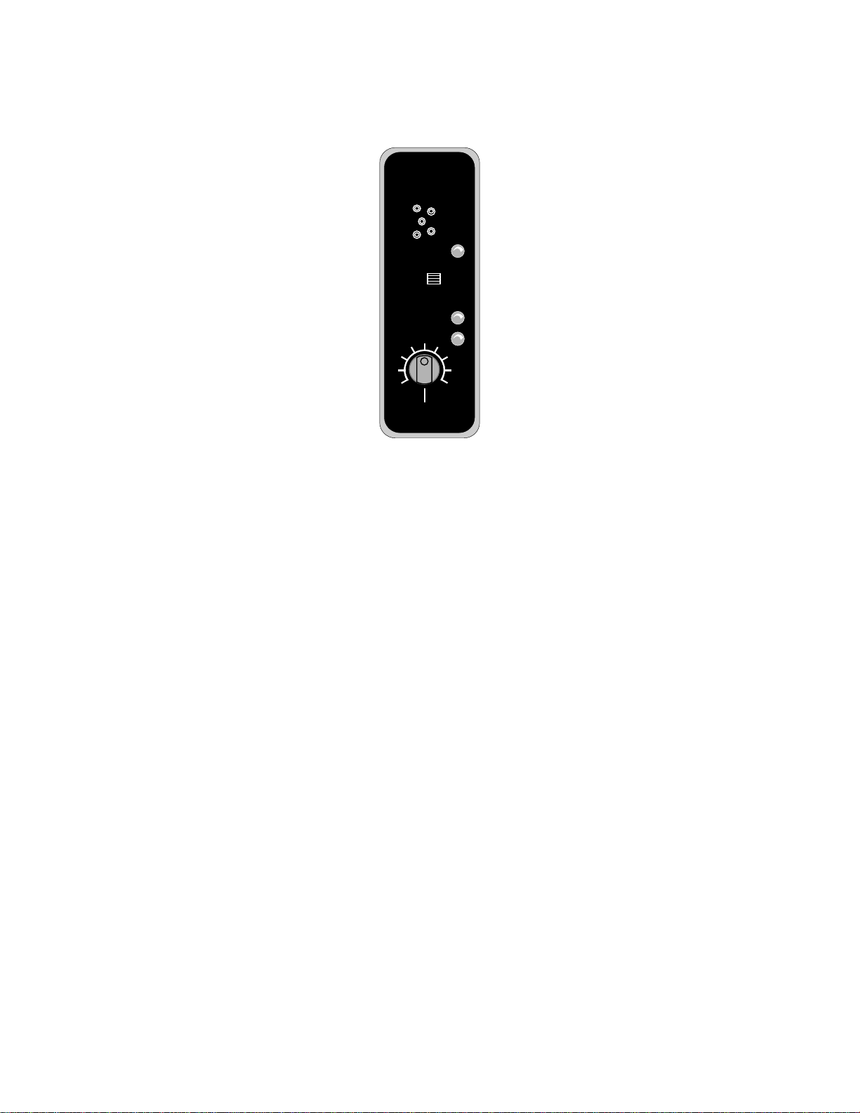
CONTROLS AND FUNCTIONS
LECTROSONICS
M185
ON
MUTE
OFF
LEVEL
LIMIT
MIC LEVEL
Figure 2 - M185 Front Panel
INPUT JACK
The input on the M185 accommodates virtually every lavalier, hand-held or shotgun microphone
available. Use a Switchcraft TA5F connector on the cord. See the separate sheet titled "M185 Input
Jack Configuration" regarding the correct connections for various microphones, and other
sources.
ON/MUTE/OFF SWITCH
Turns the battery power on and off. The center position is an "audio mute" which should be used when
setting the MIC LEVEL control to turn off the sound from the microphone during this adjustment. When
turning the transmitter on, pause for a moment in the MUTE position to prevent a turn-on surge from
occurring (a "thump" sound) in the audio.
POWER ON/OFF LED
Glows brightly when battery is good. A weak or dim lamp means that the battery is weak, and has
about an hour of operation left (maybe a little more). If the lamp fails to light, the battery should be
replaced. The power lamp should light up in both the "mute" and "on" positions of the POWER/MUTE
SWITCH.
The POWER LED is connected to a precision battery test circuit that continuously monitors battery
voltage. The LED is at full brightness with a new 9 Volt alkaline battery. As the battery voltage drops
during use, the LED brightness will also decrease. After 12 to 15 hours the battery voltage will be
about 7 Volts and the LED will be completely out.
3
Page 5

CONTROLS AND FUNCTIONS (cont’d)
Since the internal circuits are all tightly regulated and the RF output stage has a separate discrete
regulator, the transmitter will continue to operate to a battery voltage of 6.5 Volts. From 6.5 Volts to 6
Volts, the transmitter will still operate, but with degraded performance. Please note that a weak battery
will sometimes light the POWER LED immediately after turn on, but will soon discharge to the point
where the LED will go out, just like a flashlight with "dead" batteries.
The combination of an accurate battery condition indicator and regulation of all internal circuits provides
much longer battery life, as well as consistent performance over the life of the battery.
MODULATION LEDS
Indicate the proper setting of the MIC LEVEL control.
LEVEL LED
Flickers or glows when sufficient audio is present.
LIMIT LED
Lights up when the audio volume level is high enough to cause limiting.
MIC LEVEL
Used to adjust the audio input level for the proper modulation.
ANTENNA
The microphone cord is used as the antenna. A dipole antenna is formed between the shield of the
microphone cord and the metal transmitter housing.
THE BELT CLIP
The belt clip may be removed for special applications by removing the two screws.
USE ONLY THE SCREWS THAT ARE SUPPLIED
The circuitry is tightly packed into this unit. Longer screws will permanently damage the transmitter!
4
Page 6

BATTERY REPLACEMENT
Press outward on the
Swing the
battery door in this
door open
direction
The M185 transmitter is powered by a standard alkaline 9 Volt battery. It is important that you use
ONLY an ALKALINE battery for longest life. Standard zinc-carbon batteries marked "heavy-duty" or
"long-lasting" are not adequate. They will provide only about 4 hours of operation. Similarly, ni-cad
rechargeable batteries only provide 4 hours of operation or less, and will also run down quite abruptly.
Alkaline batteries provide about 15 hours of operation.
To open the battery compartment, press outward on the cover door in the direction of the arrow as
shown in the drawing. Only firm, sliding pressure is needed to open and close the battery door.
Swing the door open and take note of the polarity marked inside showing the location of the positive (+)
and negative (-) terminals. Insert the battery correctly and close the cover by pressing the door closed
and across, reversing the opening procedure illustrated above. Don’t force the door closed. The
terminals will hit a protective polarity barrier. You can see the large and small contact holes inside the
battery compartment.
Figure 3 - M185 Battery Compartment Door
5
Page 7

OPERATING INSTRUCTIONS
1) Insert the microphone plug into the input jack, aligning the pins; be sure that the connector locks in.
2) Turn the power switch to the "MUTE" position on the transmitter. The "MUTE" position allows
internal voltages to stabilize before audio signal paths are opened.
3) Position the microphone in the location you will use in actual operation.
4) Keeping the power switch in the "mute" position, speak as loudly as you expect you will in normal
system use. Rotate the MIC LEVEL knob so that the LEVEL LED flickers or stays lit as you speak.
The LIMIT LED should light up on loud "peaks." Occasional lighting of the LIMIT LED indicates proper
operation and optimum signal-to-noise ratio. Even when limiting is occurring, little or no distortion will
occur, due to the high linearity of the limiting circuitry in the M185. The input limiter will cleanly handle
peaks up to 20dB above full modulation.
5) Set up the receiver according to the receiver manual.
6) Move the switch to the "ON" position on the transmitter, verify that the modulation LEDs indicate
normally and adjust the volume of the sound system, or the record level of your recorder.
NOTE:
Do not use the MIC LEVEL control to control the volume of your sound system or the record
level on your recorder. This control should be set only as described in #4 above.
If the mic level is too high -- the LIMIT LED will light will light frequently or stay on. This condition may
cause distortion.
If the mic level is too low -- neither LED will light or the LEVEL LED will light dimly. This condition may
cause hiss and noise in the audio.
The LEVEL LED turns on at -10dB below full deviation. The LIMIT LED turns on at full deviation and
indicates that the input shunt compressor is operating. The input compressor operates over a full 20
dB range regardless of the gain control setting. The compressor uses a true absolute value circuit to
detect both positive and negative peaks. The attack time is 2 milliseconds and the release time is 80
milliseconds. Occasional limiting is desirable, indicating that the gain is correctly set and the transmitter
is being fully modulated.
6
Page 8

M185 INPUT JACK WIRING
5.1VDC
1K 1K
330
MPF480'S
7
22K
.22M
+
1uH
3.3M
+
10K
1K
5
33M
510
+
4
6
2
3
4
3
2
1
60NH
5321
1N
-
+
330PF
330PF
Bias
22K
4
3
2
1
5
TO
LIMITER
CONTROL
TO
AUDIO
CIRCUITS
LECTROSONICS
M185
M185 Transmitter
Equivalent Input Circuit
1 - NEG GND (OR BIAS)
2 - POS BIAS (OR GND)
3 - MIC
4 - SOURCE LOAD
5 - LINE IN
Vcc
The wiring diagrams shown on the attached sheet represent the basic wiring necessary for the most common types
of microphones and other audio inputs. Some microphones may require extra jumpers or a slight variation on the
diagrams shown.
Caution - When wiring the connector, do not use the connector body for any electrical
connections. A common mistake is to use the connector body as an audio ground. The
connector body is already used as an RF ground and no other use is permitted.
It’s virtually impossible to keep completely up to date on changes that other manufacturers make to their products.
It is possible that you may encounter a microphone that differs from these instructions. If this occurs please call
our toll-free number listed in the back of this instruction manual. Our service department can answer your
questions regarding microphone compatibility.
When used on a wireless transmitter, the microphone element is in the proximity of the RF coming from the
transmitter. The nature of electret microphones makes them sensitive to RF, which can cause problems with the
microphone/transmitter compatibility. If the electret microphone is not designed properly for use with wireless
transmitters, it will be necessary to install a chip capacitor in the mic capsule or connector to block the RF from
entering the electret capsule. These types of modifications are not shown on the attached instructions.
The M185 uses the shield of the microphone cord as the antenna. Other brands use a "dangling wire" to emit the
RF from the transmitter. There is really no difference between these two approaches, with respect to the effect of
the RF on the microphone capsule. Even in transmitters that utilize a "dangling wire," the microphone is still part
of the "ground plane" and is therefore still in the antenna circuit.
For answers to questions regarding microphone/transmitter compatibility, call our service manager or engineering
department at the factory.
Figure 4 - M185 Input Connector and Schematic
PIN 1 Shield (ground) for positive biased electret lavalier microphones. Bias voltage source for negative biased
electret lavalier microphones. Shield (ground) for dynamic microphones and line inputs.
PIN 2 Shield (ground) for negative biased electret lavalier microphones. Bias voltage source for positive biased
electret lavalier microphones.
PIN 3 Low impedance microphone level input for dynamic microphones. Also accepts hand-held electret
microphones provided the microphone has its own built-in battery.
PIN 4 1K ohm source load for non-Lectrosonics electret microphones. Use in conjunction with other pins to
provide attenuation of high level input signals.
PIN 5 High impedance, line level input for tape decks, mixer outputs, musical instruments, etc.
7
Page 9

TROUBLESHOOTING
Before going through the following chart, be sure that you have a good battery in the transmitter. It is
important that you follow these steps in the sequence listed.
SYMPTOM POSSIBLE CAUSE
TRANSMITTER BATTERY LED OFF 1) Battery is inserted backwards.
2) Battery is dead.
NO TRANSMITTER MODULATION LEDs 1) Gain control turned all the way down.
2) Battery is in backwards. Check power LED.
3) Mic capsule is damaged or malfunctioning.
RECEIVER RF LAMP OFF 1) Transmitter not turned on.
2) Transmitter battery is dead.
3) Receiver antenna missing or improperly
positioned.
4) Transmitter and receiver not on same frequency.
Check labels on transmitter and receiver.
5) Operating range is too great.
NO SOUND AND RECEIVER MOD LEVEL LEDs ARE OFF
1) Transmitter audio muted. Make sure front panel
power switch is in the on position.
NO SOUND BUT RECEIVER MOD LEVEL LEDs ARE ON
1) Receiver audio is muted. Refer to receiver
manual.
2) Receiver audio output is disconnected or cable is
defective or mis-wired.
3) Sound system or recorder input is turned down.
DISTORTED SOUND 1) Transmitter gain (audio level) is too high. Speak
or sing into the transmitter and check mod level
lamps on transmitter and receiver.
2) Receiver output may be mis-matched with the
sound system or recorder input.
3) Excessive wind noise or breath "pops."
HISS AND NOISE -- AUDIBLE DROPOUTS 1) Transmitter gain (audio level) too low.
2) Receiver antenna missing or obstructed.
3) Operating range too great.
EXCESSIVE FEEDBACK 1) Transmitter gain (audio level) too high. Check
gain adjustment and/or reduce receiver output
level.
2) Transmitter too close to speaker system.
3) Move transmitter closer to the user’s mouth.
8
Page 10

SPECIFICATIONS AND FEATURES
Operating frequencies: 150 to 216 MHz
RF Power output: 50 mW
Deviation: ±15 kHz (max)
Spurious radiation: 55 dB below carrier
Equivalent input noise: -126 dBV
Input level: Nominal 2 mV to 300 mV (before compression)
30 Volt max. input level (including limiter)
Input impedance: Selectable for 500, 1K, 10K Ohm
Input compressor: Soft compressor, 20 dB range
Gain control range: 43 dB; semi-log rotary control
Modulation indicators: Dual LEDs indicate modulation level and onset of limiting
Controls: 3 position "OFF-MUTE-ON" for noiseless operation
Front panel knob adjusts audio gain
Audio Input Jack: Switchcraft 5 pin locking (TA5F)
Antenna: Dipole radiator formed by mic cord shield and transmitter
housing
Battery: Precision compartment auto-adjusts to accept any known
alkaline 9 Volt battery (We’ve tried 107 of them!)
Weight: 5.3 ozs. including battery
Dimensions: 3.1 x 2.4 x .75 inches
Emission Designator: 54KOF3E
9
Page 11

SERVICE AND REPAIR
If your system malfunctions, you should attempt to correct or isolate the trouble before concluding that
the equipment needs repair. Make sure you have followed the setup procedure and operating
instructions. Check out the inter-connecting cords and then go through the TROUBLE SHOOTING
section in the manual
We strongly recommend that you do not try to repair the equipment yourself and do not have the local
repair shop attempt anything other than the simplest repair. If the repair is more complicated than a
broken wire or loose connection, send the unit to the factory for repair and service. Don’t attempt to
adjust any controls inside the units. Once set at the factory, the various controls and trimmers do not
drift with age or vibration and never require readjustment. There are no adjustments inside that will
make a malfunctioning unit start working.
LECTROSONICS service department is equipped and staffed to quickly repair your equipment.
In-warranty repairs are made at no charge in accordance with the terms of the warranty. Out of
warranty repairs are charged at a modest flat rate plus parts and shipping. Since it takes almost as
much time and effort to determine what is wrong as it does to make the repair, there is a charge for an
exact quotation. We will be happy to quote approximate charges by phone for out of warranty repairs.
RETURNING UNITS FOR REPAIR
You will save yourself time and trouble if you will follow the steps below:
A. DO NOT return equipment to the factory for repair without first contacting us by letter or by phone.
We need to know the nature of the problem, the model number and the serial number of the
equipment. We also need a phone number where you can be reached 8 am to 4 pm (Mountain
Standard Time).
B. After receiving your request, we will issue you a return authorization number (R.A.). This number
will help speed your repair through our receiving and repair departments. The return authorization
number must be clearly shown on the outside of the shipping container.
C. Pack the equipment carefully and ship to us, shipping costs prepaid. If necessary, we can provide
you with the proper packing materials. UPS is usually the best way to ship the units. Heavy units
should be "double-boxed" for safe transport.
D. We also strongly recommend that you insure the equipment, since we cannot be responsible for
loss of or damage to equipment that you ship. Of course, we insure the equipment when we ship
it back to you.
Mailing address: Shipping address:
Lectrosonics, Inc. Lectrosonics, Inc.
PO Box 15900 581 Laser Rd.
Rio Rancho, NM 87174 Rio Rancho, NM 87124
USA USA
Telephones:
Regular: (505) 892-4501
WATS: (800) 821-1121
FAX: (505) 892-6243
10
Page 12

LIMITED ONE YEAR WARRANTY
The equipment is warranted for one year from date of purchase against
defects in materials or workmanship provided it was purchased from an
authorized dealer. This warranty does not cover equipment which has
been abused or damaged by careless handling or shipping. This
warranty does not apply to used or demonstrator equipment.
Should any defect develop, we will, at our option, repair or replace any
defective parts without charge for either parts or labor. If we cannot
correct the defect in your equipment, we will replace it at no charge
with a similar new item. We will pay for the cost of returning your
merchandise to you.
This warranty applies only to items returned to us, shipping costs
prepaid, within one year from the date of purchase.
This warranty gives you specific legal rights. You may have additional
legal rights which vary from state to state.
LECTROSONICS, INC.
581 LASER ROAD
RIO RANCHO, NM 87124 USA May 12, 1994
 Loading...