

Page 1
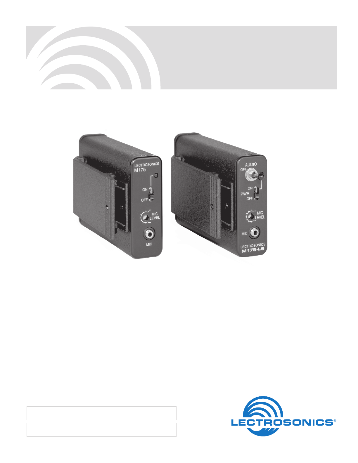
M175
Belt Pack Transmitter
INSTRUCTION MANUAL
Fill in for your records:
Serial Number:
Purchase Date:
Rio Rancho, NM, USA
www.lectrosonics.com
Page 2

M175
LECTROSONICS, INC. 2
Page 3

Belt Pack Transmitter
Table of Contents
General Description ...............................................................................................................................................................................3
Controls and Functions .........................................................................................................................................................................4
Mic Jack................................................................................................................................................................................................4
Power ON/OFF .....................................................................................................................................................................................4
Battery Indicator Lamp ......................................................................................................................................................................... 4
Mic Level Adjust ................................................................................................................................................................................... 4
Audio Switch .........................................................................................................................................................................................4
Operating Instructions .......................................................................................................................................................................... 5
Troubleshooting .....................................................................................................................................................................................6
Specifications and Features ................................................................................................................................................................. 6
Service and Repair .................................................................................................................................................................................7
Returning Units for Repair ....................................................................................................................................................................7
General Description
Thank you for selecting the M175 Wireless Microphone
Transmitter. The M175 Series transmitters operate on
high band frequencies from 150 MHz to 216 MHz. It is
offered in three different versions to meet your specific
needs. This manual covers all versions.
Only the M175 series transmitters are covered in this
manual. Receivers are covered in separate manuals.
All versions of the M175 Series transmitters will operate
with any Lectrosonics high band VHF receiver. A
frequency matched transmitter/receiver combination
makes up a “wireless system.”
If you are new to wireless microphones, you will discover a new freedom of movement and level of convenience. If you are an experienced wireless user, you
will be pleased with the versatility and superior performance of the M175 design.
The M175 Series transmitter is offered in three versions. The standard model is the M175. The M175-LS
has an additional audio mute switch on the front panel,
and the M175DC has a proprietary Digital Code
Squelch* circuit to eliminate squelching problems
caused by interference.
The digital code system provides much more reliable
control over the receiver audio output than a conventional squelch can provide. The transmitter generates
an 8-bit code at turn on, and another code at turn off, to
open and close the audio output on the receiver. The
squelch on the receiver cannot be opened by anything
other than the specific code it is programmed to receive.
This type of squelch system is even more important
when the receiver is connected into an automatic
mixing system.
The M175 transmitter uses the microphone cord for the
antenna. This feature eliminates the need for the
“dangling wire” antenna found on many transmitters.
The M175 Series transmitters use a crystal controlled
oscillator and temperature compensation circuitry to
ensure that the transmitter does not drift over time or
with age.
To suppress audible noise, a “compandor” noise
reduction circuit is used which is compatible with all
Lectrosonics 170 series, 175 series, and 185 series
receivers. In addition, the input limiting circuit will
handle >25dB of overload without distortion. The audio
circuitry is extremely quiet, with low distortion for natural
reproduction of either voice or music. The wide input
adjustment range of M175 Series transmitters allows
the use of virtually any microphone. The M175 can even
be used with modest line level inputs such as tape
recorders or musical instruments.
The M175 Series transmitters operate from a replaceable standard 9 Volt alkaline battery. A precision
battery test circuit continuously monitors the battery
voltage. A highly visible LED glows as long as the
battery voltage is high enough to operate the transmitter. A 9 Volt alkaline battery will provide up to 15 hours
of operation.
The electret microphone input jack provides 5 Volts DC
positive bias for all Lectrosonics’ electret microphones.
Many other electret microphones may be adapted to
the M175 Series by making simple wiring changes in
the microphone connector.
*DCS (Digital Code Squelch) systems require a match
between transmitter and receiver of both frequency and digital
code.
M175 Series transmitters are FCC type accepted under the
following Parts:
Part 90 (150-172 MHz), Part 74 (174-216 MHz)
Rio Rancho, NM 3
Page 4

M175
Controls and Functions
Mic Jack
The MIC JACK is a locking micro jack that supplies
“phantom power” for electret microphones such as the
Lectrosonics M119, M140 Lavalier and the HM142V,
HM152V and HM162 headset models. Insert the
microphone cord plug into the jack and
wise to lock it
locked, since the microphone cord serves as the
antenna for the transmitter.
Power ON/OFF
The POWER ON/OFF switch turns the power on and
off. The switch should be left in the OFF position when
the transmitter is not in use. When the switch is in the
ON position, the battery will be drained even though the
transmitter is not being used.
Battery Indicator Lamp
The BATTERY INDICATOR LAMP will light when the
transmitter is turned on and will stay lit as long as the
battery is good. As the battery voltage drops, the lamp
will grow dim and finally go out.
Mic Level Adjust
The MIC LEVEL ADJUST is a recessed screwdriver
adjustment used to match the gain of the transmitter to
different microphones, individual voices or other audio
inputs such as tape deck outputs.
Audio Switch
The AUDIO SWITCH (M175-LS only) is a toggle type
on-off switch used to shut off the audio signal without
shutting off the RF carrier of the transmitter.
rotate it clock-
. It is important that the plug be securely
Battery Instructions
The battery you use in the M175 Series transmitter
should be a 9 Volt lithium or alkaline, available almost
everywhere. A lithium 9 Volt battery will provide the
best performance with over 30 hours of operation. An
alkaline battery will provide up to 15 hours of operation,
and carbon zinc batteries, even if marked “heavy duty”
will only provide about 4 hours of operation. Rechargeable batteries made to look like 9 Volt batteries typically
only produce 7.2 Volts at full charge, which will only
operate the transmitter for an hour or less. Make sure
your batteries are marked “alkaline.” Short battery life is
almost always caused by weak batteries or batteries of
the wrong type.
The BATTERY LAMP will light when the transmitter is
turned on and will stay lit as long as the battery is good.
As the battery voltage drops, the lamp will grow dim
and finally go out. Even after the lamp goes out, there
may still be up to an hour or more of operating time
remaining. When the battery voltage is too low for
proper transmitter operation, the sound from the
wireless system may be distorted, intermittent or totally
absent. When the transmitter is first turned on, the
lamp may light for a short while even with a bad battery.
It is good practice to check the brightness of the lamp
after the transmitter has been on for several minutes
and to note the brightness occasionally during use.
To replace the battery, open the bottom battery door
cover with your thumb, rotate the door until it is perpendicular with the case and allow the battery to fall out of
the compartment into your hand. It is difficult to install
the battery backwards. Observe the large and small
holes in the battery contact pad before inserting a new
battery. Insert the contact end of the battery first,
making sure the contacts are aligned with the holes in
the contact pad, and then swing the door closed. You
will feel it snap into place when it is fully closed.
1
Note: The M175DC, Digital Code Squelch version
is operationally identical to the standard M175.
To open the battery
compartment door, push the
door up and away from the case
with your thumb, then swing
open.
2
LECTROSONICS, INC. 4
Page 5

Operating Instructions
Belt Pack Transmitter
This section covers adjustments to the transmitter that
must be made before the wireless microphone system
is placed into operation. The step-by-step procedures
are listed in the order in which they should be performed:
1) Turn the wireless receiver power on and make any
required preliminary adjustments in accordance
with instructions in the receiver operating instructions.
2) Plug the microphone into the transmitter. If you are
using a lavalier or headset microphone, rotate the
plug clockwise to make sure the connection is
locked.
3) Turn the transmitter power on and verify that the red
lamp on it lights. If the lamp is very dim or does not
light, replace the battery.
4) Observe that the RF lamp on the receiver control
panel is lit. This verifies that the receiver is receiving a usable radio signal from the transmitter.
5) Position the microphone on your person in the
location it will be used during actual operation. If a
headset microphone is being used, adjust the
headband for a comfortable fit with the “gooseneck”
to the left side of your head. Position the microphone element at the corner of the mouth and
rotate the white volume control fully clockwise. The
headset is designed to be worn over the head, but
can also be worn around the neck. Do not position
the microphone pickup directly in front of your
mouth as this may cause unwanted noise from
breath pops as you speak.
6) A small screwdriver is supplied with the transmitter.
The screwdriver is used to adjust the audio gain of
the transmitter to match your microphone and your
voice. The GAIN ADJUST is located on the control
panel of the transmitter as shown below. The
adjustment is made while observing the modulation
level lamps on the receiver control panel:
a) Speak at the voice level you will be using during
actual operation.
b) While speaking, adjust the transmitter gain until the
green modulation lamp on the receiver (may be
marked “-20”) is lit or flickers and the red modulation lamp blinks only on the loudest words. Raise
and lower your voice while observing the lamps.
The red lamp should blink only occasionally.
Note: The modulation lamps on some receivers
are marked or colored differently than just
described. Consult the operating manual for the
receiver in use.
7) You may now adjust the receiver output level
(wireless microphone or mic volume, level, or
volume attenuator) to the desired audio output level.
Consult your receiver manual if you are not sure of
the location of these controls.
The GAIN ADJUST is used only to adjust for proper
modulation level lamp indications. DO NOT use it to
adjust the audio output level of the receiver. Different
voices and different microphones will usually require
readjustment of the transmitter gain control, so check
the adjustment frequently. If several different people will
be using the transmitter, and there is not time to make
the adjustment for each individual, adjust it for the
loudest voice.
WHILE SPEAKING,
ADJUST THE TRANSMITTER
AS YOU OBSERVE THE LEDs
ON THE RECEIVER
Rio Rancho, NM 5
Page 6

M175
Troubleshooting
Before going through the following chart, be sure that you have a good battery in the transmitter. It is important that
you follow these steps in the sequence listed.
Symptom: Possible Cause:
Transmitter battery LED off 1) Unit turned off. Check front panel on/off slide switch.
2) Battery is inserted backwards.
3) Battery is dead.
Receiver RF lamp off 1) Transmitter not turned on.
2) Transmitter battery is dead.
3) Receiver antenna missing or improperly positioned.
4) Transmitter and receiver not on same frequency.
Check labels on transmitter and receiver.
5) Operating range is too great.
No sound and receiver 1) Transmitter audio muted (M175-LS only)
mod level LEDs are off 2) Microphone or input cable defective.
No sound but receiver 1) Receiver audio is muted. Refer to receiver manual.
mod level LEDs are on 2) Receiver audio output is disconnected or cable is defective
or mis-wired.
3) Sound system or recorder input is turned down.
Distorted sound 1) Transmitter gain (audio level) is too high. Speak or sing into the
transmitter and check mod level lamps on the receiver
(see Operating Instructions.)
2) Receiver output may be mis-matched with the sound system
or recorder input.
3) Excessive wind noise or breath “pops.”
Hiss and noise -- Audible dropouts 1) Transmitter gain (audio level) too low.
2) Receiver antenna missing or obstructed.
3) Operating range too great.
Excessinve feedback 1) Transmitter gain (audio level) too high. Check gain adjustment
and/or reduce receiver output level (see Operating Instructions.)
2) Transmitter too close to speaker system.
3) Move transmitter closer to the user’s mouth.
Specifications and Features
Operating frequencies: 150 to 216 MHz
RF Power Output: 50 mW
Deviation: ±15kHz
Spurious Radiation: 50dB below carrier
Frequency Stability: ±0.005%
Equivalent Input Noise: -123dB
Input Sensitivity: 8mV to 1.6V for full modulation
Input Compressor: Soft Compressor; 12dB range
Electret Bias: +5 Volt DC (positive bias)
Antenna: Input cord or microphone body
Input Jacks: Twist-lock micro for electret
microphones
Battery Indicator:
Battery Life:
Controls:
only)
Size:
Weight:
FCC ID:
Emission designator:
Specifications subject to change without notice.
LED indicates battery condition
Approximately 15 hours
Power on/off slide switch
Recessed audio gain control
Mute on/off toggle switch (M175-LS
1.3 x 2.35 x 3.7 inches
6.6 ozs with battery and microphone
DBZM175 (150 to 172 MHz)
DBZM175A (174 to 216 MHz)
58K0F3E
LECTROSONICS, INC. 6
Page 7

Belt Pack Transmitter
Service and Repair
If your system malfunctions, you should attempt to correct or isolate the trouble before concluding that the equipment
needs repair. Make sure you have followed the setup procedure and operating instructions. Check the interconnecting cables and then go through the TROUBLESHOOTING section in this manual.
We strongly recommend that you do not try to repair the equipment yourself and do not have the local repair shop
attempt anything other than the simplest repair. If the repair is more complicated than a broken wire or loose connection, send the unit to the factory for repair and service. Don’t attempt to adjust any controls inside the units. Once set
at the factory, the various controls and trimmers do not drift with age or vibration and never require readjustment.
There are no adjustments inside that will make a malfunctioning unit start working.
LECTROSONICS’ Service Department is equipped and staffed to quickly repair your equipment. In warranty repairs
are made at no charge in accordance with the terms of the warranty. Out-of-warranty repairs are charged at a modest
flat rate plus parts and shipping. Since it takes almost as much time and effort to determine what is wrong as it does
to make the repair, there is a charge for an exact quotation. We will be happy to quote approximate charges by phone
for out-of-warranty repairs.
Returning Units for Repair
For timely service, please follow the steps below:
A. DO NOT return equipment to the factory for repair without first contacting us by letter or by phone. We need to
know the nature of the problem, the model number and the serial number of the equipment. We also need a
phone number where you can be reached 8 A.M. to 4 P.M. (U.S. Mountain Standard Time).
B. After receiving your request, we will issue you a return authorization number (R.A.). This number will help speed
your repair through our receiving and repair departments. The return authorization number must be clearly shown
on the outside of the shipping container.
C. Pack the equipment carefully and ship to us, shipping costs prepaid. If necessary, we can provide you with the
proper packing materials. UPS is usually the best way to ship the units. Heavy units should be “double-boxed” for
safe transport.
D. We also strongly recommend that you insure the equipment, since we cannot be responsible for loss of or dam-
age to equipment that you ship. Of course, we insure the equipment when we ship it back to you.
Mailing address: Shipping address: Telephone:
Lectrosonics, Inc. Lectrosonics, Inc. (505) 892-4501
PO Box 15900 581 Laser Rd. (800) 821-1121 Toll-free
Rio Rancho, NM 87174 Rio Rancho, NM 87124 (505) 892-6243 Fax
USA USA
Web: E-mail:
www.lectrosonics.com sales@lectrosonics.com
Rio Rancho, NM 7
Page 8

LIMITED ONE YEAR WARRANTY
The equipment is warranted for one year from date of purchase against defects in
materials or workmanship provided it was purchased from an authorized dealer. This
warranty does not cover equipment which has been abused or damaged by careless
handling or shipping. This warranty does not apply to used or demonstrator equipment.
Should any defect develop, Lectrosonics, Inc. will, at our option, repair or replace any
defective parts without charge for either parts or labor. If Lectrosonics, Inc. cannot
correct the defect in your equipment, it will be replaced at no charge with a similar new
item. Lectrosonics, Inc. will pay for the cost of returning your equipment to you.
This warranty applies only to items returned to Lectrosonics, Inc. or an authorized
dealer, shipping costs prepaid, within one year from the date of purchase.
This Limited Warranty is governed by the laws of the State of New Mexico. It states the
entire liablility of Lectrosonics Inc. and the entire remedy of the purchaser for any
breach of warranty as outlined above. NEITHER LECTROSONICS, INC. NOR
ANYONE INVOLVED IN THE PRODUCTION OR DELIVERY OF THE EQUIPMENT
SHALL BE LIABLE FOR ANY INDIRECT, SPECIAL, PUNITIVE, CONSEQUENTIAL,
OR INCIDENTAL DAMAGES ARISING OUT OF THE USE OR INABILITY TO USE
THIS EQUIPMENT EVEN IF LECTROSONICS, INC. HAS BEEN ADVISED OF THE
POSSIBILITY OF SUCH DAMAGES. IN NO EVENT SHALL THE LIABILITY OF
LECTROSONICS, INC. EXCEED THE PURCHASE PRICE OF ANY DEFECTIVE
EQUIPMENT.
This warranty gives you specific legal rights. You may have additional legal rights which
vary from state to state.
581 Laser Road NE • Rio Rancho, NM 87124 USA • www.lectrosonics.com
(505) 892-4501 • (800) 821-1121 • fax (505) 892-6243 • sales@lectrosonics.com
August 31, 2005
 Loading...