

Page 1
LR
Compact Wireless Receiver
INSTRUCTION MANUAL
Digital Hybrid Wireless
US Patent 7,225,135
Fill in for your records:
Quick Start Summary
1) Install receiver batteries (p.8).
2) Select frequency step size in the receiver (p.12).
3) Select the compatibility mode in the receiver (p.12).
4) Find a clear operating frequency (p.12,13).
5) Set up transmitter to match receiver (p.14).
6) Adjust transmitter input gain (p.14).
7) Adjust receiver audio output level for the connected
device (p.15).
®
Serial Number:
Purchase Date:
Rio Rancho, NM, USA
www.lectrosonics.com
Page 2

LR
2
LECTROSONICS, INC.
Page 3

Table of Contents
Introduction ............................................................................4
Three Block Tuning Range ...................................................4
RF Front-End with Tracking Filter .........................................4
IF Amplifiers and SAW Filters ..............................................4
Digital Pulse Counting Detector ...........................................4
DSP-Based Pilot Tone ..........................................................4
SmartSquelch™ ...................................................................5
SmartDiversity™ ..................................................................5
Turn On and Turn Off Delays................................................5
Test Tone .............................................................................. 5
LCD Display .........................................................................5
Smart Noise Reduction (SmartNR™) ...................................5
Panels and Features ..............................................................6
IR (infrared) Port ..................................................................6
Balanced Audio Output ........................................................6
Antenna Inputs .....................................................................6
Battery Compartment...........................................................6
USB Port ..............................................................................6
Keypad and LCD Interface ...................................................7
Battery Status and RF Link LED Indicators .........................7
LCD Main Window ...............................................................8
Installing Batteries ................................................................8
Navigating the Menus ...........................................................9
About Frequency Blocks ......................................................9
LCD Menu Tree .....................................................................10
Menu Item Descriptions ......................................................11
The Power Menu ..................................................................11
System Setup Procedures ..................................................12
Firmware Update .................................................................15
Antenna Orientation ............................................................15
Accessories .........................................................................16
Specifications ......................................................................17
Service and Repair ..............................................................18
Returning Units for Repair .................................................18
Compact Portable Receiver
FCC Notice
NOTE: This equipment has been tested and found to comply with the limits for a Class
B digital device, pursuant to Part 15 of the FCC Rules. These limits are designed to provide reasonable protection against harmful interference in a residential installation. The
equipment generates, uses and can radiate radio frequency energy and, if not installed
and used in accordance with the instructions, may cause harmful interference to radio
communications. However, there is no guarantee that interference will not occur in a
particular installation. If this equipment does cause harmful interference to radio or television reception, which can be determined by turning the equipment off and on, the user is
encouraged to try to correct the interference by one or more of the following measures:
• Reorient or relocate the receiving antenna
• Increase the separation between the equipment and receiver
• Connect the equipment into an outlet on a circuit different from that which the
• Consult the dealer or an experienced radio/TV technician for help
Changes or modifications to this equipment not expressly approved by Lectrosonics, Inc.
could void the user’s authority to operate it.
Rio Rancho, NM
receiver is connected
3
Page 4
LR
TUNING RANGE
Introduction
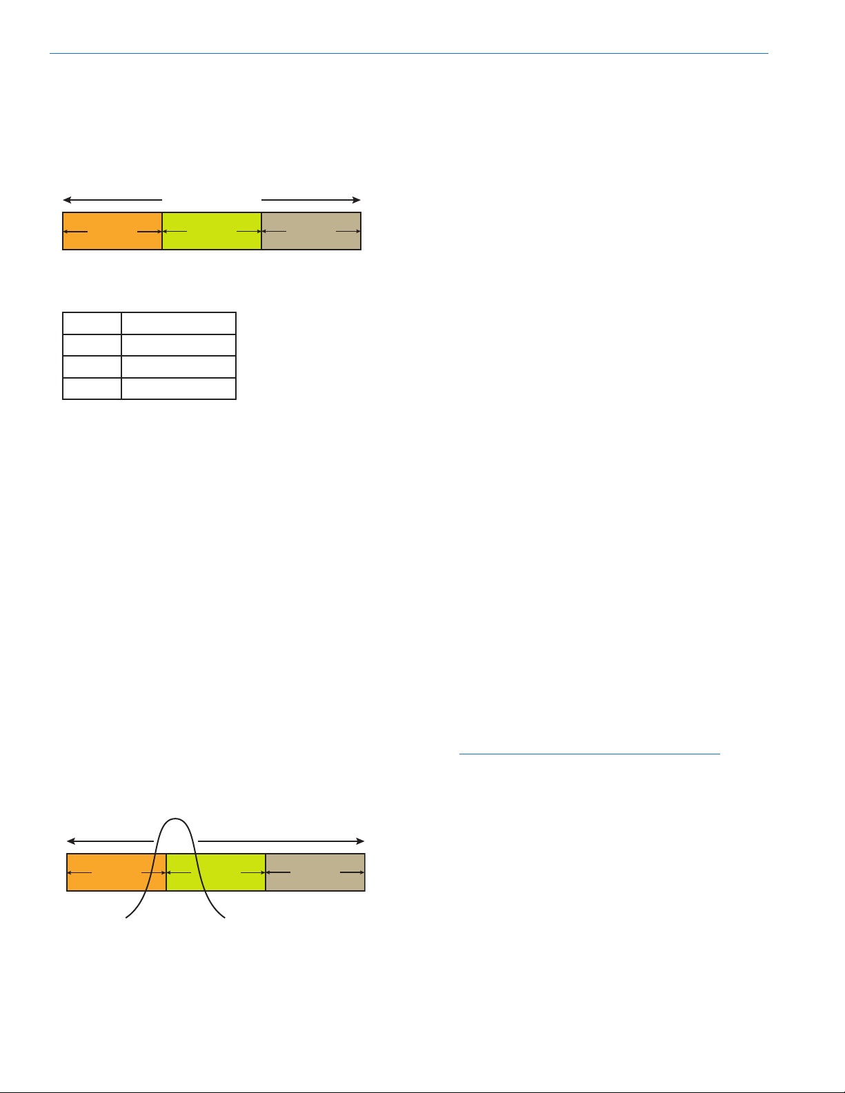
Three Block Tuning Range
The LR receiver tunes across a range of over 76 MHz.
This tuning range covers three standard Lectrosonics
frequency blocks. See page 9 for more information.
BLOCK
Four tuning ranges are available covering standard
blocks as follows:
Range Blocks Covered
A1 470, 19, 20
B1 21, 22 23
C1 24, 25, 26
D1 27, 28, 29
To simplify backward compatibility with earlier Digital
Hybrid Wireless® equipment, block numbers are presented along with frequencies in LCD screens.
BLOCK
RF Front-End with Tracking Filter
A wide tuning range is helpful in finding clear frequencies for operation, however, it also allows a greater
range of interfering frequencies to enter the receiver.
The UHF frequency band, where almost all wireless
microphone systems operate, is heavily populated
by high power TV transmissions. The TV signals are
immensely more powerful than a wireless microphone
transmitter signal and will enter the receiver even when
they are on significantly different frequencies than the
wireless system. This powerful energy appears as
noise to the receiver, and has the same effect as the
noise that occurs with extreme operating range of the
wireless system (noise bursts and dropouts). To alleviate this interference, front-end filters are needed in the
receiver to suppress RF energy below and above the
operating frequency.
The LR receiver employs a variable frequency, tracking filter in the front-end section (the first circuit stage
following the antenna). As the operating frequency is
changed, the filters re-tune to stay centered over the
selected carrier frequency.
BLOCK
IF Amplifiers and SAW Filters
The first IF stage employs two SAW (surface acoustic
wave) filters. The use of two filters significantly increases the depth of filtering while preserving sharp skirts,
constant group delay, and wide bandwidth. Though
expensive, this special type of filter allows primary
filtering as early as possible, at as high a frequency as
possible, before high gain is applied, to deliver maximum image rejection. Since these filters are made of
quartz, they are very temperature stable.
The signal is converted to 243.950 MHz in the first
mixer stage, then passed through two SAW filters. After the SAW filter, the IF signal is converted to 250 kHz
and then the majority of the gain is applied. Although
these IF frequencies are unconventional in a wide
deviation (±75 kHz) system, the design provides excellent image rejection.
Digital Pulse Counting Detector
Followign the IF section, the receiver uses an elegantly
simple, yet highly effective digital pulse counting
detector to demodulate the FM signal to generate the
audio, rather than a conventional quadrature detector.
This unusual design eliminates thermal drift, improves
AM rejection, and provides very low audio distortion.
The output of the detector is fed to the microprocessor
where a window detector is employed as part of the
squelch system.
DSP-Based Pilot Tone
The Digital Hybrid system design uses a DSP generated ultrasonic pilot tone to reliably mute the audio
when no RF carrier is present. The pilot tone must be
present in conjunction with a usable RF signal before
the audio output will be enabled. 256 pilot tone frequencies are used across each 25.6 MHz block within
the tuning range of the system. This alleviates erroneous squelch activity in multichannel systems where a
pilot tone signal can appear in the wrong receiver via
IM (intermodulation).
Pilot tones are also provided for legacy equipment and
some models from other manufacturers.
Note: This description applies only to the Digital
Hybrid mode. In Lectrosonics 200 Series, IFB
and Mode 6 compatibility, only one pilot tone
frequency is used on all frequencies, emulating
the original crystal-based system. In other
compatibility modes, no pilot tone is used.
BLOCK
In the front-end circuitry, a tuned filter is followed by an
amplifier and then another filter to provide the selectivity needed to suppress interference, yet provide a
wide tuning range and retain the sensitivity needed for
extended operating range.
4
BLOCK
BLOCK
LECTROSONICS, INC.
Page 5

Compact Portable Receiver
SmartSquelch
A DSP-based algorithm named SmartSquelchTM optimizes the receiver performance in very weak signal conditions. The RF level and supersonic noise in the audio
are continuously monitored to determine the appropriate
noise reduction needed and the point at which squelch
(complete muting of the audio) is necessary.
As the RF level decreases and supersonic noise in the
signal begins to increase, a variable knee, high frequency
roll-off filter is applied to suppress high frequency noise.
The filtering action moves in and out smoothly to avoid
abrupt changes that could be audible. When the RF
signal becomes so weak that the receiver can no longer
deliver usable audio, the squelch will activate.
SmartDiversity
Microprocessor controlled antenna phase combining
is used for diversity reception. The firmware analyzes
RF level, the rate of change of RF level and the audio
content to determine the optimum timing for phase
switching and the optimum antenna phase. The system
also employs “opportunistic switching” to analyze and
then latch the phase in the best position during brief
squelch activity.
™
™
Turn On and Turn Off Delays
A brief delay is applied when the receiver is powered
up or down to prevent audible noise such as a thump,
pop, click or other transient noise.
Test Tone
To assist in matching the audio levels of equipment
connected to the receiver, a 1 kHz audio test tone generator is provided, with an output level adjustable from
-50 to +5 dBu in 1 dB increments.
The tone simulates the audio output with a steady signal at full modulation, making it easy to adjust the level
to precisely match the optimal level for the connected
device and maximize the signal to noise ratio of the
system.
LCD Display
Setup and monitoring is done through the LCD display
on the control panel. The LCD image can be inverted
as desired for personal preference or maximum visibility in direct sunlight. The built-in backlight for viewing
in dimly lit environments can be set to remain on for 30
seconds, 5 minutes or to remain on constantly.
Smart Noise Reduction (SmartNR™)
Note: The SmartNR setting is user selectable
only in the Digital Hybrid compatibility mode. In
other modes, noise reduction is applied in such a
way as to emulate the original analog system as
accurately as possible and is not user adjustable.
The wide dynamic range of digital hybrid technology, combined with flat response to 20 kHz, makes it
possible to hear the -120 dBV noise floor in the mic
preamp, or the (usually) greater noise from the microphone itself. To put this in perspective, the noise
generated by the recommended 4k bias resistor of
many electret lavaliere mics is –119 dBV and the noise
level of the microphone’s electronics is even higher. In
order to reduce this noise the receiver is equipped with
a “smart” noise reduction algorithm called SmartNR®,
which removes hiss without sacrificing audio high
frequency response.
SmartNR® works by attenuating only those portions of
the audio signal that fit a statistical profile for randomness or “electronic hiss.” Because it is much more than
a sophisticated variable low pass filter, the transparency of the audio signal is preserved. Desired high
frequency signals having some coherence are not
affected, such as speech sibilance and tones.
The Smart Noise Reduction algorithm has three
modes, selectable from a user setup screen. The
optimal setting for each application is subjective and is
normally selected while simply listening.
• OFF defeats noise reduction and complete transparency is preserved. All signals presented to the
transmitter’s analog front end, including any faint
microphone hiss, will be faithfully reproduced at
the receiver output.
• NORMAL applies enough noise reduction to
remove most of the hiss from the microphone
preamp and some of the hiss from lavaliere microphones. The noise reduction benefit is significant
in this position, yet the degree of transparency
maintained is exceptional.
• FULL applies enough noise reduction to remove
most of the hiss from nearly any signal source of
reasonable quality and some high frequency environmental noise, assuming the input gain is set
properly at the transmitter.
Rio Rancho, NM
5
Page 6
LR
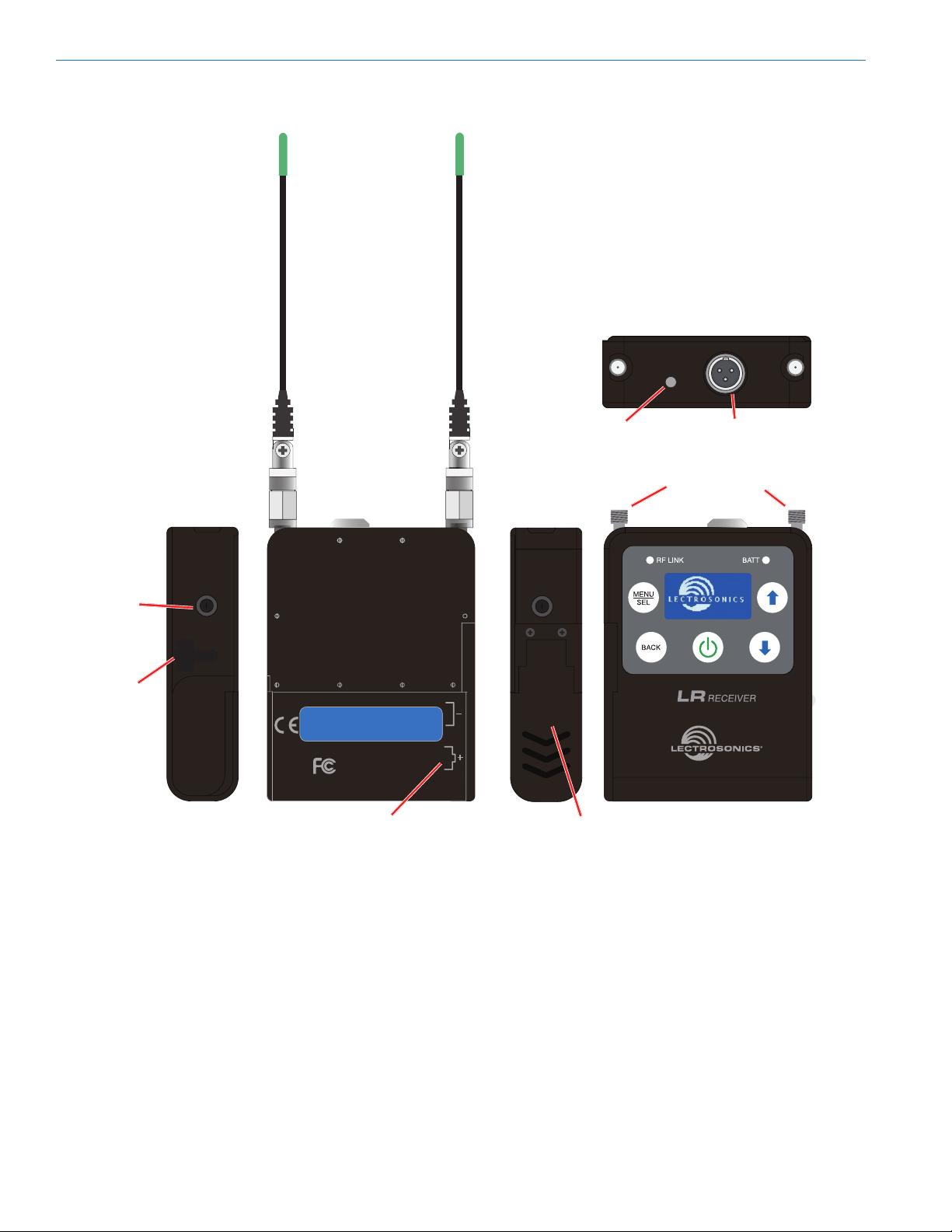
Panels and Features
Belt clip
mounting
hole
USB Port
CAN ICES-3 (B)/NMB-3(B)
Model: LR-XX Made in the USA
Serial No. XXXXX
Frequency block XXX (XXX.X - XXX.X MHz)
This device complies with part 15 of the FCC rules.
Operation is subject to the condition that this device
does not cause harmful interference.
CAN RSS-Gen/CNR-Gen
IR (infrared)
Port
IR PORT
Balanced Audio
Antenna Inputs
AUDIO
OUT
Output
Battery polarity
IR (infrared) Port
Settings for compatibility mode and frequency can be
transferred from the receiver via this port to an IR enabled transmitter to simplify setup. The receiver is used
to scan for a clear frequency, and the new frequency
can be sent to the transmitter via the IR ports.
Balanced Audio Output
Balanced or unbalanced audio from mic to line level
is provided on the TA3 output jack; adjustable in 1 dB
steps from -50 dBu to +5 dBu.
6
Battery
Compartment
Door
Antenna Inputs
Two standard 50 ohm SMA connectors can be used
with whip antennas or coaxial cable connected to
remote antennas.
Battery Compartment
Two AA batteries are installed as marked on the rear
panel of the receiver. The battery door is hinged and
remains attached to the housing.
USB Port
Firmware updates are made easy with the USB port
on the side panel.
LECTROSONICS, INC.
Page 7

Compact Portable Receiver
Keypad and LCD Interface
RF LINK LED
Glows blue when a valid RF signal is being received.
BATT LED
Glows green when the batteries are good. As the batteries are drained, the LED will turn to a steady red
at a mid-point during their life, then begin to blink red
when only a few minutes of operation remain.
MENU/SEL Button
Pressing this button enters the menu and selects
menu items to enter the setup screens.
BACK Button
Pressing this button returns to the previous menu or
screen.
Power Button
Turns the unit off and on and enters the power menu.
Arrow Buttons
Used to navigate the menus.
Battery Status and RF Link LED Indicators
Alkaline, lithium or rechargeable batteries can be used
to power the receiver. For accurate battery status indications, select the type of batteries you will be using in
the menu.
Transmitter
signal
received
RF LINK LED
When a valid RF signal from a transmitter is received,
this LED will light up blue. Depending upon the selected compatibility mode, a pilot tone may also be required to light up the LED and open the squelch on the
receiver. If the necessary pilot tone is not present, but
the RF signal is on the correct frequency, the RF level
indicator on the LCD will display a signal presence, but
the RF LINK LED will not light up.
BATT LED
When the battery status LED on the keypad glows
green the batteries are good. The color changes to red
at a midpoint during the runtime. When the LED begins
to blink red, only a few minutes remain.
The exact point at which the LED turns red will vary
with battery brand and condition, temperature and
power consumption. The LED is intended to simply
catch your attention, not to be an exact indicator of
remaining time.
A weak battery will sometimes cause the LED to glow
green immediately after the transmitter is turned on,
but it will soon discharge to the point where the LED
will turn red or the unit will turn off completely.
Rechargeable batteries give little or no warning when
they are depleted. If you wish to use these batteries in
the receiver, you will need to manually keep track of
the operating time to prevent interruptions caused by
dead batteries.
RF
signal
strength
Battery
status
LED
Rio Rancho, NM
7
Page 8

LR
LCD Main Window
Frequency
in MHz
RF level Diversity
Audio
level
activity
Transmitter battery
elapsed time
RF level
The triangle graphic corresponds to the scale on the
left side of the display. The scale indicates the incoming signal strength in microvolts, from 1 uV at the bottom to 1,000 uV (1 millivolt) at the top.
Diversity activity
This icon flips upside down and back as the SmartDiversity antenna phase combining circuitry operates.
Pilot tone
This icon will appear in compatibility modes where a
supersonic pilot tone is used in squelch control. The
icon will blink if a pilot is expected but not present on
the incoming signal.
Frequency in MHz
The example here shows the frequency expressed in
MHz (megahertz) when the StepSize is set to 100 kHz.
When the StepSize is set to 25 kHz, the display will
include three numerals to the right of the decimal point.
Frequency in hex code
The characters (CD in the above example) indicate
the frequency expressed with hexadecimal numerals
to simplify backward compatibility with older transmitters that use two rotary switches to set the operating
frequency. See About Frequency Blocks on the next
page for more information.
Frequency block in use
The tuning range of the receiver covers three standard
frequency blocks. The hex code numbers are repeated
in each block, so the block number must be associated
with the hex code number to define a frequency.
Transmitter battery elapsed time
A timer is included to monitor the runtime of the transmitter, which is especially useful when using rechargeable batteries. The timer runs whenever a valid signal
is being received from the transmitter, and stops when
the signal is no longer being received. The display
shows the accumulated runtime in hours and minutes.
Audio level
This bar graph indicates the level of the audio entering
the transmitter. The “0” at the right side of the graph
indicates full modulation and the onset of limiting.
Pilot
tone
Frequency
block in use
Frequency
in hex code
Full
modulation
Installing Batteries
Power is provided by two AA batteries. Alkaline, lithium
or NiMH types can be used. The batteries are connected in series by a plate in the battery door.
Slide the battery
door outward to
open it
Polarity is marked on the rear panel.
Polarity markings
8
LECTROSONICS, INC.
Page 9

Navigating the Menus
Menu setup items are arranged in a vertical list on
the LCD. Press MENU/SEL to enter the menu, then
navigate with the UP and DOWN arrows to highlight
the desired setup item. Press MENU/SEL to enter the
setup screen for that item. Refer to the menu map on
the following page.
Press MENU/
SEL to enter
the menu
Press the UP and DOWN arrows
to navigate and highlight the
desired menu item
Press MENU/
SEL to
enter the
setup of the
highlighted
item
Press BACK
to return to
the previous
screen
About Frequency Blocks
A 25.6 MHz band of frequencies, referred to as a
Block, came about with the design of the first frequency tunable Lectrosonics wireless products. These
products provided two 16-position rotary switches to
select frequencies as shown in the illustration below. A
logical method of identifying the switch positions was
using 16 character hexadecimal numbering. This naming and numbering convention is still used today.
The 16 switch positions are numbered 0 (zero) through
F, presented in a two-character designation such as
B8, 5C, AD, 74, etc. The first character indicates the
position of the left hand switch and the second character indicates the position of the right hand switch. This
designator is commonly called a “hex code.”
Compact Portable Receiver
Each block spans a 25.6 MHz band. A simple formula
is used to name the blocks according to the lowest
frequency in each one. For example, the block starting
at 512 MHz is named Block 20, since 25.6 times 20
equals 512.
As the available RF spectrum has changed, special
blocks have been created to cover different bands than
the simple formula described above. Block 470, for
example, is named according to the lower end of the
frequency range, expressed in MHz, rather than the
formula described above.
The L-Series wireless products tune across a 3-block
range, and can tune in either 100 kHz or 25 kHz steps,
as shown in the table below. Letter prefixes and a numeral designate the tuning range of a transmitter and
receiver. Special subsets of each tuning range may
become necessary, and if so, will have names such as
A2, A3, etc.
Range Blocks covered Freq. (MHz)
A1 470 thru 20 470.1 - 537.5
B1 21 thru 23 537.6 - 614.3
C1 24 thru 26 614.4 - 691.1
D1 27 thru 29 691.2 - 767.9
The hex code is repeated in each 25.6 MHz block, so
it will appear up to 3 times across one tuning range.
For this reason, the block that a selected frequency
falls within is in the upper right corner of the LCD, just
above the hex code.
Block number
Hex code
FREQUENCY
1.6MHz
0
0
F
1
1
F
E
2
2
E
3
D
3
D
C
C
4
4
5
B
5
B
6
A
6
A
9
9
7
7
8
8
100kHz
On older transmitter models, the left hand
switch makes steps in 1.6 MHz increments,
the right hand switch in 100 kHz increments.
Rio Rancho, NM
9
Page 10

LR
LCD Menu Tree
The menus presented on the LCD are arranged in a
straightforward manner, with those that are likely to be
used more often located at the top of the tree.
Smart Tune
Frequency
IR Sync
RF Scan
Clear Scan
Audio Level
Step Size
Tx Battery
SEL
SEL
SEL
SEL
SEL
SEL
SEL
SEL
Tx Block
BACK
Frequency
BACK
IR Sync
BACK
BACK
BACK
BACK
BACK
BACK
Press
Press SEL to stop scanning,
select WideView, ZoomView
or resume scanning
scan data
CLEARED
Audio Level
+05 dBu
Step Size
Tx Battery
B1
21
B1 NA
22
23 NA
23
Block 21 B1
555.300 MHz
100 kHz
25 kHz
Select from
listings
B1
Press UP arrow
to start transfer
Use arrow keys
to select desired
audio output level
Use arrow keys
to select desired
scanning range
Press SEL to
select desired
adjustment step
Use arrow keys to scroll
cursor; SEL + arrow for
fine steps
Use arrow keys to
select step size
Use arrow keys to
select battery type
SEL
SEL +
wait
for
scan
IR Sync
Press
Use arrow keys
to select desired
frequency
BACK
Toggles 1k tone
output
NOTE: The transmitter battery timer is
included in the Tx Battery setup screen
Keep scan freq?
(select option)
Rx Battery
Compat.Mode
Polarity
Smart NR
Sq. Bypass
Backlight
LCD Mode
Default
SEL
SEL
SEL
SEL
SEL
SEL
SEL
SEL
BACK
BACK
BACK
BACK
BACK
BACK
BACK
BACK
Rx Battery
Compat.Mode
Polarity
Smart NR
Squelch Bypass
Backlight Time
LCD Mode
Retore Factory
default settings
Select from
listings
Select from
listings
Normal
Inverted
Off
Normal
Full
Normal
Bypass
Always On
30 Seconds
5 Minutes
Wht on Blk
Blk on Wht
No
Yes
Use arrow keys to
select battery type
Use arrow keys to select
compatibility mode
Use arrow keys to select
audio output polarity
Use arrow keys to select
noise reduction preference
Use arrow keys to enable or
disable squelch (audio mute)
Use arrow keys to select
LCD backlight duration
Use arrow keys to select
LCD mode
Use arrow keys to accept or reject
restoration of default settings
10
LECTROSONICS, INC.
Page 11

Menu Item Descriptions
Compact Portable Receiver
Smart Tune
An automatic scanning function that identifies a usable
frequency and sets the receiver on it. After the scan is
complete, an option will appear to transfer the settings
to an IR enabled transmitter. The receiver will remain
set on the newly discovered frequency whether or not
the IR transfer option was used.
Frequency
Allows manual selection of the operating frequency.
IR Sync
Transfers frequency, step size and compatibility mode
from the receiver to the associated transmitter.
RF Scan
Launches the manual spectrum scanning function.
Clear Scan
Erases scan results from memory.
Audio Level
Adjusts the audio output level of the receiver.
Step Size
Selects 100 kHz or 25 kHz steps in the frequency
adjustments.
Tx Battery
Selects the type of battery being used in the associated transmitter for accurate battery status monitoring.
The transmitter battery timer option is included in this
setup screen.
Backlight
Selects the length of time the backlight on the LCD
remains turned on.
LCD Mode
Selects the text/background appearance of the LCD.
Default
Returns all settings to the factory defaults:
Menu Item Setting
Frequency 8,0 (middle of lowest frequency
block)
Audio Level 0 dBu
Compat.Mode NA Dig. Hybrid
Smart NR Normal
Polarity Normal (not inverted)
Step Size 100 kHz
LCD Mode White characters on dark
background
Tx Battery AA alkaline
Rx Battery Alkaline
Battery Timer Reset to 0
Sq. Bypass Normal (squelch operational)
Tone output Off (in Audio Level setup
screen)
Backlight Always on
Keypad status Not locked
Rx Battery
Selects the type of battery being used in the receiver
for accurate battery status monitoring.
Compat. Mode
Selects the compatibility mode for use with a wide variety of Lectrosonics and other brands of transmitters.
Polarity
Selects the audio polarity (phase) of the receiver output to match other components and different microphone capsule wiring.
Smart NR
Selects the level of noise reduction applied to the
audio signal.
Sq. Bypass
Defeats the audio muting (squelch) to allow audio
output from the receiver regardless of the presence
or lack of a matching transmitter. Used for diagnostic
purposes.
Rio Rancho, NM
The Power Menu
Pressing the power button opens a menu with several options. Use the UP and DOWN arrows to select
the option and press MENU/SEL to select the function
or open a setup screen.
Resume
Returns to the previous screen and settings.
LockUnlock
Opens a setup screen with options to Lock or Unlock
the buttons.
About
Displays the splash screen shown at bootup, which
includes the firmware version.
Power Off
Turns the power off.
11
Page 12

LR
System Setup Procedures
Summary of Steps
1) Install receiver batteries and select the battery
type in the setup screen.
2) Select frequency step size in the receiver.
3) Select the compatibility mode in the receiver.
4) Find a clear operating frequency with one of two
different methods (use one or the other).
a) Using Smart TuneTM
b) Manually
5) Set up transmitter to matching frequency and compatibility mode.
6) Adjust transmitter input gain.
7) Adjust receiver audio output level to match recorder, camera, mixer, etc.
1) Install Receiver Batteries
Install the batteries according to the diagram marked
on the back of the housing and select the battery type
in the menu. Check the BATT LED on the control panel
to verify adequate power is present - the LED should
glow green.
2) Select Frequency Step Size
Navigate to Step Size in the LCD menu and select
100 kHz or 25 kHz as needed to match the associated
transmitter.
3) Select Receiver Compatibility Mode
Navigate to Compat.Mode on the menu and press
MENU/SEL to enter the setup screen. The optional
modes will appear one at a time. Use the UP and
DOWN arrow buttons to scroll through the list. When
the desired mode appears in the screen, press MENU/
SEL or BACK to select the mode and return to the previous menu. Press BACK to return to the Main Window.
Transmitter Models LCD menu item
US Digital Hybrid
Wireless
Mode 3* Mode 3
200 Series 200 Series
100 Series 100 Series
Euro Digital Hybrid
Wireless®
300 Series: 300 Series
Mode 7* Mode 7
Mode 6* Mode 6
IFB Series IFB
NA Dig. Hybrid is the best mode to use when both
transmitter and receiver are North American Digital
Hybrid Wireless models (not Euro/E01 variants).
®
NA Dig. Hybrid
EU Dig. Hybrid
Mode 3 is a special compatibility mode for use with another brand of wireless. Contact the factory for details.
200 Series works with legacy Lectrosonics models
such as all UM200, UH200 and UT200 Series transmitters.
100 Series works with Lectrosonics UM100 transmitters.
EU Dig. Hybrid works with Lectrosonics European
Digital Hybrid transmitters with model numbers that
end in “/E01.” For example, the SMDB/E01 transmitter
is in this group.
300 Series works with legacy Lectrosonics transmitters that were sold in Europe, such as the UM300B
and UT300.
Mode 7 is a special compatibility mode for use with another brand of wireless. Contact the factory for details.
Mode 6 is a special compatibility mode for use with another brand of wireless. Contact the factory for details.
IFB works with Lectrosonics models such legacy
analog models bearing “IFB” in the model number, or
Digital Hybrid Wireless models that offer the IFB compatibility mode.
4a) Find a Clear Frequency with Smart Tune
Optimum range will be realized if the system is set
to a frequency where few or no other RF signals are
present (a “clear” frequency). The receiver can select a
clear frequency automatically with Smart TuneTM.
Navigate to Smart Tune in the LCD menu and press
MENU/SEL to start the process. Select the desired
range to be scanned, then press MENU/SEL to start
the scan.
Entire tuning range
Individual blocks(NA) North American
versions
NOTE: “NA” next to the block numbers indicates
the North American version which excludes the
radio astronomy band from 608 to 614 MHz.
TM
12
LECTROSONICS, INC.
Page 13

Cursor scrolls
across screen
during scanning
When the scan is complete a screen will appear briefly
to display the frequency chosen by Smart Tune, and
then it will change to IR Sync. If you are using a Lectrosonics transmitter that has an IR port, the settings
can be transferred from the receiver to the transmitter
in a few seconds with a single button.
As shown below, IR Sync will prompt you to place
the receiver and transmitter close to one another and
press the UP arrow button. Hold the units within two
feet or so apart with the IR ports facing each other,
then press the button. The transmitter LCD will display
a message confirming the receipt of the settings.
NOTE: IR sync transfers the settings for
frequency, step size and compatibility mode.
Compact Portable Receiver
Press the MENU/SEL button to pause the scan.
Use the UP and DOWN buttons to scroll the marker
through the graphical image. Press MENU/SEL to
increase the resolution while scrolling.
Use arrow buttons to scroll marker
Press MENU/SEL to increase
the resolution in scrolling.
Press MENU/SEL to zoom in on the image. Scroll using the buttons as described above.
If you are not using a Lectrosonics transmitter with an
IR port, simply return to the Main Window and observe
the frequency that was chosen by Smart Tune. Make
sure the compatibility mode selected in the receiver is
correct for the transmitter in use. Then set the transmitter on the frequency chosen by Smart Tune.
4b) Find a Clear Frequency Manually
Navigate to RF Scan on the menu and press MENU/
SEL to start the scanning. The LCD will display a
marker that travels across the screen as a graphical
image of the RF energy appears. The marker will wrap
back to the beginning and continue to repeat.
RF energy Clear spectrum
After scrolling the marker to a spot in the clear spectrum in the display, press BACK to open a menu with
three options.
Use the arrow keys to select the option, then press
MENU/SEL to store the setting and return to the Main
Window.
• Keep stores the new frequency and returns to
the Main Window.
• Keep + IRSync stores the frequency, then moves
to the IR Sync screen. Copy the frequency to the
transmitter and then press BACK to return to the
Main Window.
• Revert discards the new frequency and returns
to the Main Window.
• Press BACK to return to scanning
Rio Rancho, NM
Strong RF
energy
Clear
spectrum
13
Page 14

LR
5) Set Up Transmitter to Matching Frequency
and Compatibility Mode
If you have not already set the frequency on the
transmitter in the previous procedures, use IR Sync or
complete the settings manually.
Lectrosonics transmitters with IR Sync:
On the LR receiver, navigate to IR Sync on the menu
and press the MENU/SEL button. Hold the transmitter
and receiver fairly close to each other (within two feet
or so) and position them so the IR ports are facing one
another. Press the UP arrow on the receiver to initiate
the transfer of settings. The receiver will display a message when the settings have been received.
Other transmitters:
Frequency, input gain, etc, are set with the controls on
the transmitter. The correct compatibility mode must
also be selected on the receiver.
6) Adjust Transmitter Input Gain
NOTE: This adjustment is very important, since
it will determine the signal to noise ratio and
dynamic range that the system will deliver.
Lectrosonics transmitters with LCD interface:
The LEDs on the control panel provide an accurate
indication of modulation level to assist in adjusting the
input gain. The LEDs will glow either red or green to
indicate modulation levels as shown in the following
table. Full modulation is achieved at 0 dB, when the
“-20” LED first turns red. The limiter can cleanly handle
peaks up to 30 dB above this point.
Signal Level -20 LED -10 LED
Less than -20 dB Off Off
-20 dB to -10 dB Green Off
-10 dB to +0 dB Green Green
+0 dB to +10 dB Red Green
Greater than +10 dB Red Red
3) Prepare the signal source. Position a microphone
the way it will be used in actual operation and have
the user speak or sing at the loudest level that
will occur during use, or set the output level of the
instrument or audio device to the maximum level
that will be used.
4) Use the and arrow buttons to adjust the gain
until the –10 dB glows green and the –20 dB LED
starts to flicker red during the loudest peaks in the
audio.
5) Once the transmitter input gain has been set, the
signal can be sent to the sound system or recorder
for level adjustments, monitor settings, etc.
6) Do not use the transmitter input gain control to
adjust the audio output level of the receiver.
Other Transmitters:
Earlier Lectrosonics transmitters provide LEDs to accurately indicate full modulation, with continuously variable gain controls for a precise adjustment. The LEDs
operate in the same manner as those shown here for
transmitters with an LCD interface.
The UM400A transmitter shown below is typical of
many legacy Lectrosonics models.
LECTROSONICS
UM400a
ON
OFF
AUDIO
LEVEL
–10
–20
ANTENNA
Input gain
control
Modulation
level LEDs
NOTE: It is best to go through the following
procedure with the transmitter in the standby
mode so that no audio will enter the sound
system or recorder during adjustment.
1) With fresh batteries in the transmitter and power
the unit on in the standby mode (a brief press on
the power switch with L-Series transmitters).
2) Navigate to the Gain setup screen.
Gain
LineIn
Gain
25
Freq.
ProgSw
14
-40
-20
0
Some transmitters from brands other than Lectrosonics can also be used if the appropriate compatibility
mode set is set in the receiver. Observe the audio level
meter on the LR receiver LCD as you adjust the input
gain on the transmitter to see the modulation level.
Some models may have limiters on the input to suppress overload distortion, and others may not. Monitor
the audio, preferably with headphones, as you adjust
the input gain to find the maximum level that can be
set without audible limiting or overload distortion.
LECTROSONICS, INC.
Page 15

Compact Portable Receiver
7) Set Receiver Audio Output Level
The audio output can be adjusted from -50 dBu (mic
level) to +5 dBu (line level) in 1 dB steps. It is best to
use an output level high enough to drive the connected
device to an optimal level without the need for additional gain. If the receiver is set to full output and the level
is still not sufficient to drive the connected device to an
optimal level, then some gain will need to be applied
by the connected device.
A built-in tone generator makes matching the output
level to the connected device easy and accurate.
1) Navigate to Audio Level in the LR receiver menu
and press MENU/SEL to enter the setup screen.
Use the arrow keys to reduce the level to minimum
(-50 dBu).
2) Turn on the 1k tone (MENU/SEL + UP arrow) in
the Audio Level setup screen.
3) On the connected device, set the input to “line
level” if available. Turn the input gain control (e.g.
record level) all the way down.
4) Gradually increase the output level on the receiver
while observing the input level meter on the connected device. Increase the level until the input
level meter indicates 3 or 4 dB below maximum.
This “optimal level” will protect against overloading
the input with a very loud peak in the audio.
5) If this optimal level cannot be achieved, even with
the receiver output turned all the way up, increase
the input gain control on the connected device
gradually until this level is achieved.
Once this level match has been set, leave these settings alone and make adjustments from one event to
another with the input gain control on the transmitter.
Antenna Orientation
The antennas are most sensitive perpendicular to the
axis of the whip. The pattern is a toroidal (donut) shape
surrounding the antenna. A cross section of the pattern
is depicted in the illustrations below.
The best orientation is to keep the antenna whips
elevated and oriented vertically to provide a circular
pattern around the transmitter and receiver. The whips
can point up or down.
The receiver can be mounted horizontally and swiveling antennas can be adjusted to keep the whips in a
vertical orientation, as shown in Fig. 2.
It is also good practice to keep the antennas away
from metallic surfaces.
Fig. 1
STRONG
SIGNAL
Tx
Tx
Rx
Rx
Rx
Fig. 2
STRONG
SIGNAL
Fig. 3
Firmware Update
As of the date of this writing, the firmware update program runs only on a Windows operating system.
Updating the firmware is simply a matter of downloading a utility program and file from the web site and
running the program with the receiver connected to a
computer via the USB port.
Go to www.lectrosonics.com/US. Click on SUPPORT
in the top bar, then click on L-Series in the categories list. Click on the link labeled Firmware Updates
at the bottom of the screen. Download the Firmware
Updater program zip file and extract it to a temporary
folder on your computer. Then download and extract
the firmware zip file (e.g. lrv1_16.zip) and extract it to a
temporary folder on your computer.
Hold down the UP and DOWN arrow buttons on the
receiver while powering it up. The receiver will display
UPDATE to confirm it is in this mode. Plug in the USB
cable and run the utility program. The program will
automatically detect the receiver and prompt for the
location of the firmware file. Point at the file and click
on Start. The process takes about 90 seconds.
Rio Rancho, NM
Rx
WEAK
SIGNAL
Tx
Fig. 4
Tx
WEAKEST
SIGNAL
15
Page 16

LR
Accessories
MCLRTRS
Audio cable; LR output; TA3F to 3.5 mm TRS male; 20
inch length. Wired for mono output (tip and ring are
combined).
MCSRTRS
Audio cable; dual LR output; two TA3F to one 3.5 mm
male TRS; 11 inch length.
AMJ(xx) Rev. A
Whip antenna; swiveling. Specify frequency block.
AMM(xx)
Whip antenna; straight. Specify frequency block.
MCSRXLR
Audio cable; LR output; TA3F to XLR-M; 12 inch length.
LRSHOE
Accessory shoe mount; requires 26895 belt clip.
About Whip Antenna Frequencies:
Frequencies for whip antennas are specified by the
block number. For example, AMM-25 is the straight
whip model cut to the block 25 frequency.
L-Series transmitters and receivers tune across a
range covering three blocks. The correct antenna for
each of these tuning ranges is the block in the middle
of the tuning range.
Range Blocks covered Ant. Freq.
A1 470 thru 20 Block 19
B1 21 thru 23 Block 22
C1 24 thru 26 Block 25
D1 27 thru 29 Block 28
26895
Wire belt clip.
16
LECTROSONICS, INC.
Page 17

Specifications
Compact Portable Receiver
Operating Frequencies:
Tuning range A1: 470.100 - 537.575 MHz
Tuning range B1: 537.600 - 614.375 MHz*
Tuning range C1: 614.400 - 691.175 MHz
Tuning range D1: 691.200 - 767.975 MHz (export only)
*North American transmitter models exclude the radio astronomy band
from 608 to 614 MHz.
Frequency selection steps: Selectable; 100 kHz or 25 kHz
Receiver Type: Dual conversion, superheterodyne
IF Frequencies: 243.950 MHz and 250.000 kHz
Frequency stability: ±0.001 %
Front end bandwidth: 20 MHz @ -3 dB
Sensitivity:
20 dB SINAD: 1.0 uV (-107 dBm), A weighted
60 dB Quieting: 2.2 uV (-100 dBm), A weighted
Squelch quieting: Greater than 100 dB typical
Modulation acceptance: +/-100 kHz max.; varies with selected
compatibility mode
Image and spurious rejection: 85 dB
Third order intercept: 0 dBm
Diversity method: SmartDiversityTM phased antenna
combining
FM detector: Digital Pulse Counting Detector
RF spectrum analyzer: Single and multiple block scanning modes
with coarse and fine views of results
Antenna inputs: 50 Ohm; SMA female connectors
Audio output: TA3 male (mini XLR) balanced output
Audio output level: Adjustable -50 to +5 dBu in 1 dB steps
(unbalanced output level is 6 dB lower)
Front panel controls
and indicators: • Sealed panel with membrane switches
• LCD for setup menus and monitoring
Audio test tone: 1 kHz, -50 dBu to +5 dBu output (bal);
.04% THD
Transmitter battery type
selection: • AA alkaline
• AA lithium
• Timer available for use with all types
Audio polarity selection: Normal or inverted
Compatibility modes: • Digital Hybrid (North American)
• Digital Hybrid (European)
• Lectrosonics 100
• Lectrosonics 200
• Lectrosonics 300
• Lectrosonics IFB
• Non-Lectrosonics mode 3
• Non-Lectrosonics mode 6
• Non-Lectrosonics mode 7
(contact the factory for details)
SmartNR (noise reduction): • OFF
• NORMAL
• FULL
(available in Digital Hybrid modes only)
Audio Performance:
Frequency Response: 32 Hz to 20 kHz (+/- 1 dB) receiver only
(see transmitter documentation for overall
system response)
THD: < 0.4 (0.2% typical in Digital Hybrid mode)
Top panel features: • TA3M audio output jack;
• (2) SMA antenna jacks
• IR (infrared) port
Battery types: • AA alkaline
• AA Lithium
• AA NiMH rechargeable
Operating runtime: 4 hours, AA alkaline
Operating temperature: -20° C to +50°C
Weight: 221 grams (7.1 ozs.) with two AA alkaline
batteries and two AMJ-Rev. A antennas
Dimensions (housing): 3.21 x 2.45 x .84 in. (82 x 62 x 21 mm)
Specifications subject to change without notice
Rio Rancho, NM
17
Page 18

LR
Service and Repair
If your system malfunctions, you should attempt to correct or isolate the trouble before concluding that the equipment needs repair. Make sure you have followed the setup procedure and operating instructions. Check the interconnecting cables.
We strongly recommend that you do not try to repair the equipment yourself and do not have the local repair shop
attempt anything other than the simplest repair. If the repair is more complicated than a broken wire or loose connection, send the unit to the factory for repair and service. Don’t attempt to adjust any controls inside the units.
Once set at the factory, the various controls and trimmers do not drift with age or vibration and never require readjustment. There are no adjustments inside that will make a malfunctioning unit start working.
LECTROSONICS’ Service Department is equipped and staffed to quickly repair your equipment. In warranty repairs
are made at no charge in accordance with the terms of the warranty. Out-of-warranty repairs are charged at a modest flat rate plus parts and shipping. Since it takes almost as much time and effort to determine what is wrong as it
does to make the repair, there is a charge for an exact quotation. We will be happy to quote approximate charges by
phone for out-of-warranty repairs.
Returning Units for Repair
For timely service, please follow the steps below:
A. DO NOT return equipment to the factory for repair without first contacting us by e-mail or by phone. We need
to know the nature of the problem, the model number and the serial number of the equipment. We also need a
phone number where you can be reached 8 A.M. to 4 P.M. (U.S. Mountain Standard Time).
B. After receiving your request, we will issue you a return authorization number (R.A.). This number will help
speed your repair through our receiving and repair departments. The return authorization number must be
clearly shown on the outside of the shipping container.
C. Pack the equipment carefully and ship to us, shipping costs prepaid. If necessary, we can provide you with
the proper packing materials. UPS or FEDEX is usually the best way to ship the units. Heavy units should be
“double-boxed” for safe transport.
D. We also strongly recommend that you insure the equipment, since we cannot be responsible for loss of or dam-
age to equipment that you ship. Of course, we insure the equipment when we ship it back to you.
Lectrosonics USA:
Mailing address: Shipping address: Telephone:
Lectrosonics, Inc. Lectrosonics, Inc. +1 (505) 892-4501
PO Box 15900 561 Laser Rd., Suite 102 (800) 821-1121 Toll-free US and Canada
Rio Rancho, NM 87174 Rio Rancho, NM 87124 Fax +1 (505) 892-6243
USA USA
Web: E-mail:
www.lectrosonics.com service.repair@lectrosonics.com
sales@lectrosonics.com
Lectrosonics Canada:
Mailing Address: Telephone: E-mail:
720 Spadina Avenue, +1 (416) 596-2202 Sales: colinb@lectrosonics.com
Suite 600 (877) 753-2876 Toll-free Canada Service: joeb@lectrosonics.com
Toronto, Ontario M5S 2T9 (877) 7LECTRO
Fax (416) 596-6648
18
LECTROSONICS, INC.
Page 19

Compact Portable Receiver
Rio Rancho, NM
19
Page 20

LIMITED ONE YEAR WARRANTY
The equipment is warranted for one year from date of purchase against defects in
materials or workmanship provided it was purchased from an authorized dealer. This
warranty does not cover equipment which has been abused or damaged by careless
handling or shipping. This warranty does not apply to used or demonstrator equipment.
Should any defect develop, Lectrosonics, Inc. will, at our option, repair or replace any
defective parts without charge for either parts or labor. If Lectrosonics, Inc. cannot
correct the defect in your equipment, it will be replaced at no charge with a similar new
item. Lectrosonics, Inc. will pay for the cost of returning your equipment to you.
This warranty applies only to items returned to Lectrosonics, Inc. or an authorized
dealer, shipping costs prepaid, within one year from the date of purchase.
This Limited Warranty is governed by the laws of the State of New Mexico. It states the
entire liablility of Lectrosonics Inc. and the entire remedy of the purchaser for any
breach of warranty as outlined above. NEITHER LECTROSONICS, INC. NOR
ANYONE INVOLVED IN THE PRODUCTION OR DELIVERY OF THE EQUIPMENT
SHALL BE LIABLE FOR ANY INDIRECT, SPECIAL, PUNITIVE, CONSEQUENTIAL,
OR INCIDENTAL DAMAGES ARISING OUT OF THE USE OR INABILITY TO USE
THIS EQUIPMENT EVEN IF LECTROSONICS, INC. HAS BEEN ADVISED OF THE
POSSIBILITY OF SUCH DAMAGES. IN NO EVENT SHALL THE LIABILITY OF
LECTROSONICS, INC. EXCEED THE PURCHASE PRICE OF ANY DEFECTIVE
EQUIPMENT.
This warranty gives you specific legal rights. You may have additional legal rights which
vary from state to state.
581 Laser Road NE • Rio Rancho, NM 87124 USA • www.lectrosonics.com
+1(505) 892-4501 • fax +1(505) 892-6243 • (800) 821-1121 US and Canada • sales@lectrosonics.com
17 June 2015
 Loading...