

Page 1

*
LE8
LOGIC CONTROLLED EQUALIZER MODULE
OPERATING INSTRUCTIONS
and trouble-shooting guide
LECTROSONICS, INC.
Rio Rancho, NM
* Patent No: 5,206,913
Page 2

INTRODUCTION
Thank you for purchasing the Lectrosonics LE8 Logic Controlled Equalizer. The LE8 represents a significant
advance in equalization technology. The LE8, when used in an automatic Modular Audio Processor system,
provides an economical solution to the problem of multiple microphone equalization and notch filtering. Each of up
to eight microphones may be equalized using a four band equalizer. In addition, three variable frequency notch
filters are available for each microphone. This allows all microphones to be individually optimized for best quality
sound, and the feedback frequencies that are unique to each microphone position may be eliminated.
The heart of the LE8 is a sophisticated microprocessor, which controls all functions of the digitally programmed EQ
and notch filters. The microprocessor also reads all user accessible controls to provide user interface. When a
microphone becomes active, the appropriate EQ curve and notch filter frequencies are loaded, into the digitally
programmed filters in the LE8. Since the filters in the LE8 are "time-shared" between all microphones, very
sophisticated filtering can be provided at a reasonable cost.
TABLE OF CONTENTS
INTRODUCTION .......................................... 1
GENERAL TECHNICAL DESCRIPTION .......................... 2
EQUALIZATION AND NOTCH FILTERING ........................ 3
FRONT PANEL DESCRIPTION ................................ 4
REAR PANEL DESCRIPTION ................................. 5
INSTALLATION ........................................... 6
OPERATING INSTRUCTIONS ................................. 7
MULTIPLE LE8 SETUP ...................................... 8
TROUBLESHOOTING ....................................... 9
SERVICE AND REPAIR ..................................... 10
RETURNING UNITS FOR REPAIR ............................. 10
SPECIFICATIONS ......................................... 11
WARRANTY ........................................ Back cover
The LE8 is FCC type accepted under the following Parts:
Part 15
1
Page 3
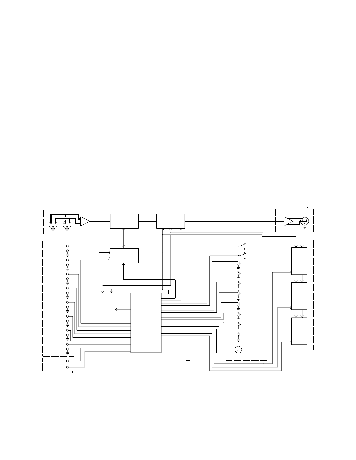
GENERAL TECHNICAL DESCRIPTION
The LE8 is comprised of five major functional subsystems: the balanced input, the programmable four band
equalizer, three programmable notch filters, the balanced and floating output driver, and the microprocessor (see
block diagram below).
The input circuit of the LE8 is a fully balanced, RF filtered differential amplifier. The balanced circuit topology
provides high rejection of common mode signals. It may also be configured to accept unbalanced signals.
The balanced and floating output driver is fully RF filtered, and provides the benefits of transformer coupling without
the low frequency distortion and core saturation that plagues transformers. High current operational amplifiers are
used in the output driver, allowing long cable runs to be driven easily. The output driver may also be easily
configured for unbalanced use.
The microprocessor, a Motorola MC68HC705C8, provides all control and interface functions for the LE8. The
MC68HC705C8 has internal non-volatile memory which stores the control program for the LE8 (note that filter setup
values are stored in a separate off-chip non-volatile memory with data retention that exceeds 100 years). The
microprocessor also provides both parallel and serial ports for interfacing with filters, controls, and indicators. The
high integration density of the microprocessor allows for a much lower parts count design, thus increasing reliability.
All filters are programmed by the microprocessor as appropriate for the particular active microphone. In addition, all
user controls are scanned by the microprocessor to provide the user interface. Link In and Link Out functions are
provided so that more than one LE8 may be used in an installation.
INPUT AMPLIFIER
LOGIC INPUTS
LOGIC IN #8
LOGIC IN #7
LOGIC IN #6
LOGIC IN #5
LOGIC IN #4
LOGIC IN #3
LOGIC IN #2
LOGIC IN #1
LINK IN
LINK OUT
LINK IN/OUT
NOTCH FILTERS AND TONE CONTROLS
4 BAND
PROGRAMMABLE
TONE CONTROL
EEPROM
MEMO RY
3 NOTCH FILTERS
PROGRAMMABLE
50-5KHz
8 LINES
SERIAL/PARALLEL
CONVERTER
NOTCH FILTER DATA LATCH
SERIAL DATA OUT (S DO)
MEMO RY
LATCH
SERIAL CLOCK (SC)
MICROPROCESSO R
MICROPROCESSOR AND NON-VOLATILE MEMORY
Figure 1 - LE8 Block Diagram
TONE CONTROL
DATA LATCH
USER CONTROLS
ROTARY ENCODER
NOTCH/E Q DISPLAY L ATCH
ACTIVE LOGIC IN DISPLAY LATCH
FUNCTION LED DISPLAY LATCH
OPERATE
NEW SETTING
ACTIVE
BYPASS
STORE SETTING
NOTCH
#1
NOTCH
#2
NOTCH
#3
TREBLE
MID TREBLE
MID BASS
BASS
ADJUST
OUTPUT AMPLIFIER
NOTCH
FREQUENCY
EQ LEVEL
DISPLAY
ACTIVE
LOGIC
INPUT
DISPLAY
FUNCTION
LED
DISPLAY
USER DISPLAY
2
Page 4
EQUALIZATION AND NOTCH FILTERING
FOUR BAND PROGRAMMABLE EQUALIZER
The four band programmable equalizer contains both low and high frequency shelving filters, as well as mid bass
and mid treble bandpass type filters. The low frequency (bass) filter hinge frequency (the frequency at which cut or
boost begins) is 1 kHz. The mid bass center frequency is 300Hz, and the Q of the filter is 0.33. The mid treble
center frequency is 3 kHz, and the Q of the filter is also 0.33. The high frequency (treble) filter hinge frequency is
1.2 kHz. All filters can be adjusted for 10dB of cut or boost. The LE8 uses one filter set with programmable
parameters (instead of eight separate filter sets) to implement the tone controls and notch filters. The filter set is
"time-shared" between up to eight mics. This time sharing is accomplished using the logic outputs from the AP4 or
EP4 module to signal which microphone is active at any time. The filter parameters associated with the active mic
are then loaded into the programmable filter. Needless to say, only one mic at a time may be equalized. When
two or more mics are active, the mic which activates the highest number Logic In on the LE8 will have its filter
parameters loaded. For instance, if mics 2 and 4 were both on, the filter parameters for mic 4 would be loaded.
BASS
+10 dB
+5 dB
0 dB
-5 dB
-10 dB
Hz Hz Hz kHz kHz kHz
MIDBASS
MIDTREBLE TREBLE
201011004010
Figure 2 - LE8 Tone Control Curves
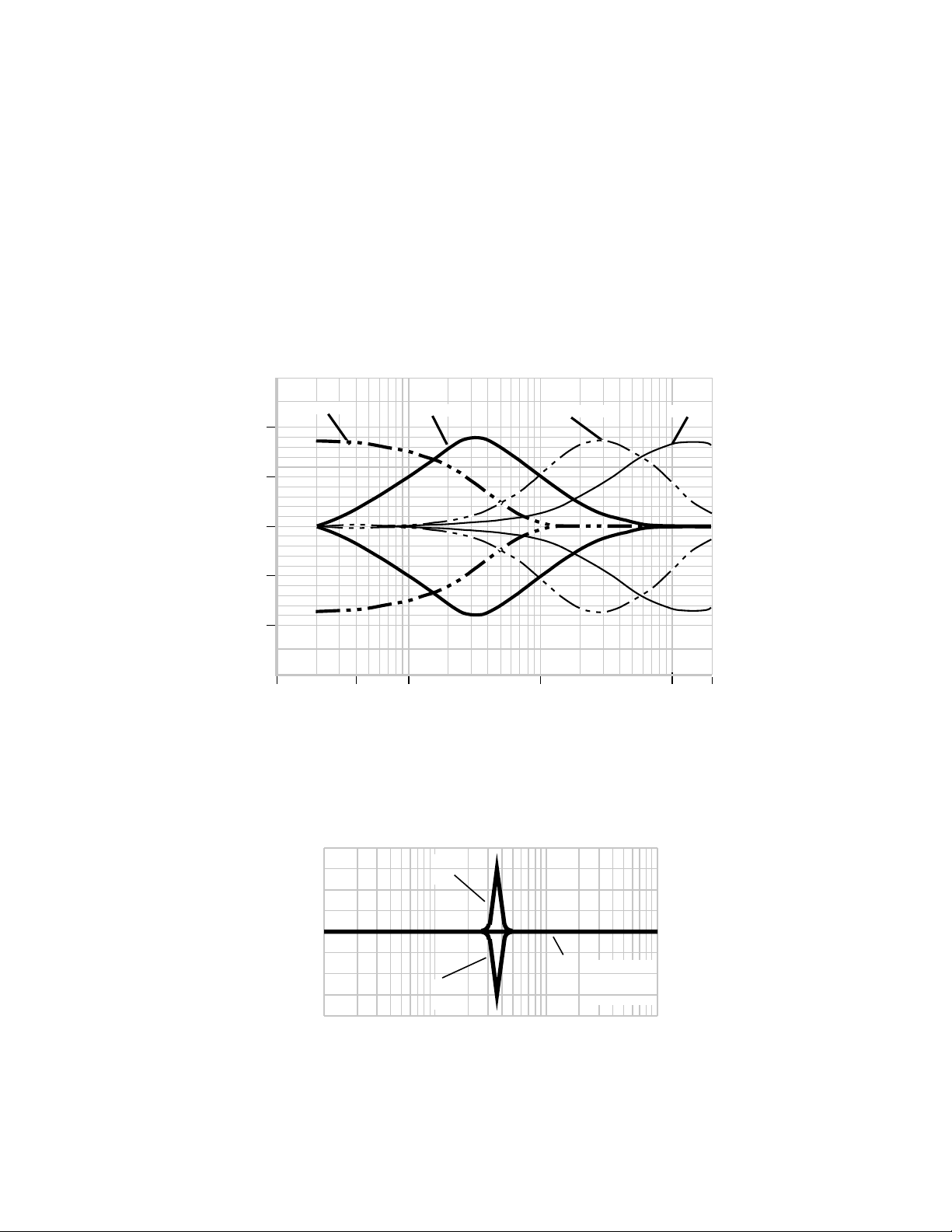
NOTCH FILTERS
The three programmable notch filters are of the fixed depth, variable frequency type. Notch depth is 12dB, and the
notches are 1/7 of an octave wide. The filters are designed to be easily tunable, while being completely inaudible.
The center frequency can be varied from 50Hz to 5kHz. Frequency resolution from 50Hz to 500Hz is 1.76Hz, and
resolution from 500Hz to 5kHz is 19.4Hz.
12
ROOM RESPONSE WITH
RINGING
6
dB 0
-6
REQUIRED NOTCH
FILTER
ROOM RESPONSE
AFTER NOTCH
FILTERING
-12
20 200 2K 20K
FREQUENCY IN HERTZ
Figure 3 - LE8 Notch Filter Example
3
Page 5

AUDIO PROCESSOR
LE
8
SETTING
STORE
NEW SETTING
OPERATE
3
2
1
+
-
ADJUST
-10
-9
-8
-7
-6
-5
-4
-3
-2
-1
50
100
150
200
250
300
350
400
450
500
OFF
500
BASS
BASS
MID
TREBLE
MID
TREBLE
EQUALIZER
LEVEL
EQ
FREQ
NOTCH
0
+1
+2
+3
+4
+5
+6
+7
+8
+9
+10
1K
1.5
2K
2.5K
3K
3.5K
4K
4.5K
5K
8
7
6
5
4
3
2
1
BYPASS
ACTIVE
5,206,913
PATENT NO:
ACTIVE
LOGIC
INPUT
NOTCH
FILTERS
FRONT PANEL DESCRIPTION
ACTIVE/BYPASS SWITCH - The Active/Bypass switch provides the user a means to bypass both the equalization
and notch filters in the LE8. All other functions and controls are active (consistent, of course, with the position of
the Operate/New Setting switch). When the Active/Bypass switch is in the Bypass mode, the Link Out signal is
brought to logic low.
ACTIVE LOGIC INPUT DISPLAY - The Active Logic Input LEDs indicate the Logic Input whose associated filter
parameters are currently loaded. The Active Logic Input LED will continue to
be on until another Logic Input is active. Note that the LEDs stay on even if
the previously active microphone is no longer in use, until another Logic Input
becomes active. The LEDs will blink if the Active/Bypass switch is switched
into the Bypass mode.
EQUALIZER (TREBLE, MID TREBLE, MID BASS, BASS) - The Equalizer
buttons select which of the equalizer filter functions is currently active. The
LEDs associated with the buttons serve to indicate which function is active
after the button is pressed. Once a filter function has been selected, it may
be adjusted using the Adjust control. Note that these buttons are active only
when the Operate/New Setting switch is in the New Setting position.
NOTCH FILTERS (1, 2, AND 3) - The Notch Filter buttons select which of
the notch filters is currently active. The LEDs associated with the buttons
serve to indicate which filter is active after the button is pressed. Once a
filter function has been selected, it may be adjusted using the Adjust control.
Note that these buttons are active only when the Operate/New Setting switch
is in the New Setting position.
NOTCH FREQUENCY/EQ LEVEL DISPLAY - The Notch Frequency/EQ
Level display indicates the particular setting of the selected filter function.
When one of the equalizer filters is active, the LEDs indicate the amount of
cut or boost of the selected filter function. Adjustment range for the equalizer
filters is +/-10dB in 1dB steps. When one of the three notch filters is
selected, the LEDs indicate the frequency nearest the center of the selected
filter.
OPERATE/NEW SETTING - The Operate/New Setting switch controls the
operational mode of the LE8. In the Operate position, the LE8 scans the
Logic Inputs and Link In. If an active Logic In is detected, and if Link In is at
logic low, then the appropriate filter set is loaded into the programmable
filters. All user controls except the Active/Bypass switch are ignored in the
Operate mode. In the New Setting mode, operation is identical to the
Operate mode with the exception that all user controls are active.
STORE SETTING - The Store Setting button provides a means for saving
the filter parameter of the currently active filter to the non-volatile memory
associated with the currently active Logic Input. Pressing the store setting
button will store the setting of the currently active filter functions only and
cause the currently active filter function LED to blink once to indicate
successful filter value storage. Note that the Store Setting button is only
active when the Operate/New Setting switch is in the New Setting position.
TO RESET MEMORY - To restore the original factory settings, hold down the
NOTCH FILTER 3 and STORE SETTING buttons while turning on the MAIN
POWER SWITCH on the AC1, EC1, or SC1. The EQ and NF LEDs will
blink. Now turn the MAIN POWER SWITCH off, release the buttons, and
turn the MAIN POWER switch back on. Memory is now reset to original
factory settings.
Figure 4 - LE8 Front Panel
4
Page 6

REAR PANEL DESCRIPTION
LE8
UNBAL
IN/OUT
SHIELD 1
2
SIG +
3
SIG -
(Shield)
LOGIC INPUTS 1-8 - The Logic Inputs provide the input for a contact closure (or other means) to indicate to the
LE8 what filter set should be loaded. A contact closure (i.e. a short) between the Logic Input "+" and Logic Input "-"
is needed to activate the input (this is referred to as "active low logic"). Logic Input "+" is connected through a 10K
Ohm resistor to the internal +5 Volt supply, and Logic Input "-" is connected to the internal digital ground. Any
contact closure (or other means) used must be able to conduct 0.5 mA continuous DC current. The Logic Inputs
are pre-assigned a priority to prevent confusion when two or more channels
are active. Logic Input 8 is the highest priority input, and Logic Input 1 is the
lowest. For example, if both Logic Inputs 2 and 4 were simultaneously
active, the filter set for Logic Input 4 will be loaded.
LINK OUT - The Link Out connector provides a means to use more than one
LE8 in an installation. This terminal should be connected to the Link In
terminal of the next LE8 used in systems where more than one LE8 is used.
The Link Out of that LE8 should be connected to the Link In of the next LE8,
and so on. (See page 7 for wiring detail.)
PATENT NO: 5,206,913
1
LINK IN - The Link In connector, in conjunction with the Link Out connector,
provides a means to use more than one LE8 in an installation. This terminal
should be connected to the Link Out terminal of the previous LE8 used in
systems where more than one LE8 is used.
INPUT - The Input connector is a standard female balanced 3-pin XLR. Pin
2 is signal "+", Pin 3 is signal "-", and Pin 1 is ground. The Input may be
used either balanced or unbalanced. If the Input is used unbalanced, a 2
wire plus shield type cable should be used. Refer to the diagram below for
the proper wiring for unbalanced inputs and outputs.
THRU - The Thru connector (a male 3-pin XLR) parallels the Input connector,
and is used for daisy chaining the input signal to the LE8 on to other devices.
Note that since the Thru is directly parallel to the Input, if the Input is run
unbalanced, the Thru will also be unbalanced.
OUTPUT - The Output connector is a standard male balanced and floating 3pin connector. Pin 2 is signal "+", Pin 3 is signal "-", and Pin 1 is ground.
The Output may be used either balanced or unbalanced. If the Output is
used unbalanced,a2wireplusshieldtype cable should be used. Refer to
the diagram below for the proper wiring for unbalanced inputs and outputs.
2
3
4
5
6
7
8
AUDIO
INPUT
AUDIO
THRU
LOGIC
INPUTS
Figure 6 - Wiring for unbalanced use.
LINK OUT
LINK IN
AUDIO
OUTPUT
LE 8
AUDIO PROCESSOR
Figure 5 - LE8 Rear Panel
5
Page 7

INSTALLATION
SYSTEM INSTALLATION - The LE8 module, like any other equalization module, will normally be driven from either
the AC1 Main Output, or from an EQN1 (if there is one in the system). The output signal from the LE8 should be
routed to a DP1 (if there is one in the system), an XO2 or XO3 (if there is one in the system), or to the system
power amplifier input.
MECHANICAL INSTALLATION
Prior to installing the LE8 module into the mainframe, the position of the LINK mode jumper must be set. See the
illustration below. The default setting is the jumper set on pins2&3forasingleLE8 installedinthe system. If
you plan to link two or more LE8 modules then the jumper should be moved to pins1&2.
The LE8 module is installed from the rear of the Modular Audio Processor mainframe. The printed circuit board fits
into one of the ten sets of card guides provided in the mainframe. The module is then slid forward in the
mainframe until the female connector on the board is firmly seated on the male pins of the bus board. Care should
be taken when inserting the female connector onto the pins to be sure there is correct alignment. Four #4 machine
screws are provided to fasten the rear panel to the top and bottom rear rails of the Modular Audio Processor
mainframe. In addition, four #4 countersink machine screws are provided to secure the cover panel also provided,
to the front of the mainframe after system adjustment is complete.
ELECTRICAL INSTALLATION
Electrical interconnection from other Modular Audio Processor modules (or other equipment) to the LE8 is
straightforward. When connecting to other Modular Audio Processor modules (or other balanced in/out equipment),
simply use standard shielded XLR cables. When connecting to unbalanced equipment, see page 5 (Rear Panel
Description) for instructions on proper wiring. The Thru output may be used if a non-equalized signal is desired. If
more than one LE8 is in use, connect the Link Out of the first LE8 to the Link In of the next LE8. Then connect the
Link Out of that LE8 to the Link In of the next LE8, and so on. See the illustration on page 7.
Logic input connections are also straightforward. Connect the one of the Logic Out "+" terminals of an AP4 or EP4
module to one of the Logic In "+" terminals of the LE8. Repeat for the Logic Out "-" and Logic In "-" terminals. As
you assign each microphone in the system to one of the LE8 inputs, note that the Logic Inputs of the LE8 operate
in a priority ranking manner, with Logic Input 8 being the highest priority. This means that in the case of two or
more simultaneously active microphones, the LE8 will load the filters for the highest number microphone.
Default position
Single LE8 in system
Pins 2 & 3 jumped
1
2
3
4
1
2
3
4
Multiple LE8
(LINK MODE)
pins 1 & 2 jumped
1
2
3
4
Figure 7 - LE8 Link Mode Jumper
6
Page 8

OPERATING INSTRUCTIONS
1) Connect the LE8 into the Modular Audio Processor system as described above in the Installation section.
2) On the AC1 Main module, note the position of the THRESHOLD control and then turn the THRESHOLD control
fully clockwise. This will prevent multiple microphones from turning on during the adjustment procedure.
3) On all of the AP4 or EP4 Mic Preamp modules in the system, set the PRIORITY/AUTO/DIRECT switch on all
channels to AUTO, except the microphone to be equalized. Set this microphone to DIRECT. The Active Logic
Input LED on the LE8 corresponding to that microphone should light.
4) On the front panel of the LE8, set the ACTIVE/BYPASS switch to ACTIVE, and the OPERATE/NEW SETTING
switch to NEW SETTING.
5) Press the TREBLE button, and adjust the Treble response as appropriate using the ADJUST control. To store
this setting to permanent memory, press the STORE SETTING button. The Treble LED will blink once to
indicate that the Treble value has been saved. The same procedure may be used to adjust and save the other
three bands of equalization. The LE8 "remembers" any adjustments made in the New Setting mode, even if
they are not saved to permanent memory, until the power is turned off. This allows adjustments to be made to
all bands as many times as is necessary to achieve proper equalization. Only the final equalization values need
to be saved by pressing the STORE SETTING buttons for each filter value while the LE8 is in the NEW
SETTING mode.
6) After the microphone has been equalized, Notch Filters 1, 2, and 3 may be used to minimize feedback and
ringing problems associated with the microphone. Press the NOTCH FILTER 1 button, and increase system
gain (using the MAIN LEVEL CONTROL on the AC1) until feedback is encountered. Adjust the frequency of the
notch filter until the feedback subsides. Press the STORE SETTING button to save the setting. The Notch 1
LED will blink once to indicate that the value has been saved. Repeat this process (if desired) for Notch Filters
2 and 3.
EXAMPLE
LINK IN/OUT
and
LOGIC INPUT
CONNECTIONS
PRIORITY RANK 1 PRIORITY RANK 2 PRIORITY RANK 3
+
LOGIC IN 1
-
+
LOGIC IN 2
-
+
LOGIC IN 3
-
+
LOGIC IN 4
-
+
LOGIC IN 5
-
+
LOGIC IN 6
-
+
LOGIC IN 7
-
+
LOGIC IN 8
-
INPUT
1 2
THRU
LINK OUT
LINK IN
1 2
OUTPUT
LE8
AUDIO PROCESSOR.
+
LOGIC IN 1
-
+
LOGIC IN 2
+
LOGIC IN 3
-
+
LOGIC IN 4
-
+
LOGIC IN 5
-
+
LOGIC IN 6
-
+
LOGIC IN 7
+
LOGIC IN 8
12
3
3
3
-
INPUT
1 2
THRU
LINK OUT
LINK IN
1 2
OUTPUT
LE8
AUDIO PROCESSOR.
FROM AP4 LOGIC OUT +
FROM AP4 LOCIC OUT -
12
3
3
3
+
LOGIC IN 1
-
+
LOGIC IN 2
-
+
LOGIC IN 3
-
+
LOGIC IN 4
-
+
LOGIC IN 5
-
+
LOGIC IN 6
-
+
LOGIC IN 7
-
+
LOGIC IN 8
-
INPUT
1 2
THRU
LINK OUT
LINK IN
1 2
OUTPUT
LE8
AUDIO PROCESSOR.
3
3
3
LE8 #1 LE8 #2 LAST LE8
Figure 8 - Linking Multiple LE8s
12
7
Page 9

NOTE: To restore the original factory settings, hold down the NOTCH FILTER 3 and STORE SETTING
buttons while turning on the MAIN POWER SWITCH on the AC1, EC1, or SC1. The EQ and NF LEDs will
blink. Now turn the MAIN POWER SWITCH off, release the buttons, and turn the MAIN POWER switch back
on. Memory is now reset to original factory settings.
7) Using the PRIORITY/AUTO/DIRECT switch on the AP4 or EP4, switch the current microphone to AUTO, and the
next microphone to be adjusted to DIRECT. Repeat steps 5 and 6.
8) When all system microphones have been adjusted, reset the THRESHOLD control on the AC1 Main module to
the position it was in before this adjustment procedure, and restore the system to proper level using the MAIN
LEVEL control on the AC1. Return all PRIORITY/AUTO/DIRECT switches on the EP4(s) to the AUTO position.
Set the OPERATE/NEW SETTING switch on the LE8 to OPERATE, and be sure that the ACTIVE/BYPASS switch
is in ACTIVE. This completes the setup procedure for the LE8.
MULTIPLE LE8 SETUP
Set all mic preamp channels to "auto." Rotate THRESHOLD control on the AC1 system controller fully clockwise
(max) to keep channels off, other than the one that is being adjusted. Set all LE8 switches to "active" and
"operate."
Set up sequence:
1) Set ACTIVE/BYPASS switch on first LE8 to "active." Set OPERATE/NEW SETTING switch to "new setting."
Set desired channel to "direct" on the microphone preamp module. Verify that the CH ON LED on the desired
mic preamp channel is the only one turned on. Verify that the corresponding ACTIVE LOGIC INPUT LED on the
LE8 is also lit.
2) Select the desired EQUALIZER switch (treble, mid bass, etc.) and adjust the boost/cut as needed. Press the
STORE SETTING switch at each step once the desired adjustment is achieved. The filter function LED will blink
once to verify storage of the setting.
NOTE: It is necessary to press the STORE SETTING switch at each step of the adjustment process.
For example: TREBLE adjust > STORE
MID TREBLE adjust > STORE
MID BASS adjust > STORE
NOTCH FILTER 1 adjust > STORE
etc.
3) When the adjustments are completed for the first mic channel, set the mic preamp channel back to the "auto"
mode, and proceed to the next mic channel by setting it to "direct." Again, verify that the LEDs indicate as
described in step 1 above.
4) Once all adjustments have been made and stored for all logic inputs being used on the first module, set the
OPERATE/NEW SETTING switch to "operate" and the ACTIVE/BYPASS switch to "bypass."
5) Proceed to the next LE8 in the "chain." Go through steps 1 through 4 as listed above.
8
Page 10

TROUBLESHOOTING
SYMPTOM POSSIBLE CAUSE
Active Logic LEDs cycle through 1-8 No Active Logic Input detected
Equalizer/Notch Filter buttons and
Adjust control do not respond
Equalizer/Notch Filter buttons and
Adjust control respond, but sound
doesn’t change.
"Clicking" sound heard
when filters switch.
Operate/New Setting switch in
Operate position. Switch to New Setting
Active/Bypass switch in Bypass
position. Switch to Active.
Output of MAP system too low (too much gain at
power amp). Increase level of AC1 output and
decrease power amp gain.
9
Page 11

SERVICE AND REPAIR
If your system malfunctions, you should attempt to correct or isolate the trouble before concluding that the
equipment needs repair. Make sure you have followed the setup procedure and operating instructions. Check out
the inter-connecting cords and then go through the TROUBLE SHOOTING section in the manual
We strongly recommend that you do not try to repair the equipment yourself and do not have the local repair shop
attempt anything other than the simplest repair. If the repair is more complicated than a broken wire or loose
connection, send the unit to the factory for repair and service. Don’t attempt to adjust any controls inside the units.
Once set at the factory, the various controls and trimmers do not drift with age or vibration and never require
readjustment. There are no adjustments inside that will make a malfunctioning unit start working.
LECTROSONICS service department is equipped and staffed to quickly repair your equipment. In-warranty repairs
are made at no charge in accordance with the terms of the warranty. Out of warranty repairs are charged at a
modest flat rate plus parts and shipping. Since it takes almost as much time and effort to determine what is wrong
as it does to make the repair, there is a charge for an exact quotation. We will be happy to quote approximate
charges by phone for out of warranty repairs.
RETURNING UNITS FOR REPAIR
You will save yourself time and trouble if you will follow the steps below:
A. DO NOT return equipment to the factory for repair without first contacting us by letter or by phone. We need to
know the nature of the problem, the model number and the serial number of the equipment. We also need a
phone number where you can be reached 8 am to 4 pm (Mountain Standard Time).
B. After receiving your request, we will issue you a return authorization number (R.A.). This number will help
speed your repair through our receiving and repair departments. The return authorization number must be
clearly shown on the outside of the shipping container.
C. Pack the equipment carefully and ship to us, shipping costs prepaid. If necessary, we can provide you with the
proper packing materials. UPS is usually the best way to ship the units. Heavy units should be "double-boxed"
for safe transport.
D. We also strongly recommend that you insure the equipment, since we cannot be responsible for loss of or
damage to equipment that you ship. Of course, we insure the equipment when we ship it back to you.
Mailing address: Shipping address: Telephones:
Lectrosonics, Inc. Lectrosonics, Inc. (505) 892-4501
PO Box 15900 581 Laser Rd. (800) 821-1121
Rio Rancho, NM 87174 Rio Rancho, NM 87124 FAX: (505) 892-6243
USA USA
World Wide Web: http://www.lectrosonics.com email: sales@lectrosonics.com
10
Page 12

SPECIFICATIONS
Input:
Type Balanced and RF filtered
Impedance 20K balanced or unbalanced
Max input level +20dBu
Output:
Type Balanced, floating, and RF filtered
Impedance 100 Ohms balanced, 50 Ohms unbalanced
Max output level +20dBu
THD @ +4dBu, 20-20kHz <0.05%
IMD @ +4dBu, 60/7kHz mixed 4:1 <0.05%
Noise (20-20kHz) -90dBu
(Tone controls flat)
Equalization:
Bass Shelving type, 10dB cut/boost range
See Figure 2 on page 3 for response curves.
MidBass Bandpass type, 10dB cut/boost range
See Figure 2 on page 3 for response curves.
MidTreble Bandpass type, 10dB cut/boost range
See Figure 2 on page 3 for response curves.
Treble Shelving type, 10dB cut/boost range
See Figure 2 on page 3 for response curves.
Notch Filters: Fixed 12dB, 1/7 octave bandwidth @ -3dB points
Variable center frequency from 50-5kHz
11
Page 13

LIMITED ONE YEAR WARRANTY
The equipment is warranted for one year from date of purchase against defects
in materials or workmanship provided it was purchased from an authorized
dealer. This warranty does not cover equipment which has been abused or
damaged by careless handling or shipping. This warranty does not apply to
used or demonstrator equipment.
Should any defect develop, we will, at our option, repair or replace any
defective parts without charge for either parts or labor. If we cannot correct the
defect in your equipment, we will replace it at no charge with a similar new item.
We will pay for the cost of returning your merchandise to you.
This warranty applies only to items returned to us, shipping costs prepaid, within
one year from the date of purchase.
This warranty gives you specific legal rights. You may have additional legal
rights which vary from state to state.
LECTROSONICS, INC.
581 LASER ROAD
RIO RANCHO, NM 87124 USA August 17, 1996
 Loading...