

Page 1

LCA16
LOGIC CONTROLLED AMPLIFIER*
OPERATING INSTRUCTIONS
and trouble-shooting guide
LECTROSONICS, INC.
* US PATENT NUMBER 5204908
Rio Rancho, NM
Page 2

INTRODUCTION
Thank you for selecting the Lectrosonics LCA16 Logic Controlled Amplifier. The LCA16 is a modular multi-channel
amplifier designed to minimize feedback and audio regeneration problems in conference room sound installations
using distributed speaker systems. The speakers may be wall mounted, ceiling mounted, table mounted or any
combination thereof. For proper operation, the automatic mixer must have logic signal outputs which indicate
individual microphone activity.
The LCA16, in conjunction with an automatic mixer (such as the Lectrosonics Modular Audio Processor system)
controls the gain of each speaker, individually, in response to activity on any of the microphones in the sound
system. Any speaker can be attenuated or turned off completely by the logic output signals from the automatic
mixer channels. In addition, each channel includes a balanced line level output which may be used to drive
external amplifiers.
Each of the 16 output channels in the LCA16 provides 5 Watts into a 4 Ohm speaker (3 Watts into an 8 Ohm
speaker) and a balanced line output. A straight forward switch matrix allows each individual output channel to be
attenuated by any combination of the 16 logic inputs.
The LCA16 has integral power supplies and is designed for mounting in a standard 19-inch equipment rack. Three
front panel LEDs per channel indicate the level of attenuation. The switch matrix and attenuation level controls are
located behind a removable panel to prevent tampering or accidental mis-adjustment.
TABLE OF CONTENTS
INTRODUCTION .......................................... 1
GENERAL TECHNICAL DESCRIPTION .......................... 2
CONTROLS AND FUNCTIONS - FRONT PANEL ................... 3
CONTROLS AND FUNCTIONS - REAR PANEL .................... 5
PRE-CONFIGURING THE LCA16 PRIOR TO INSTALLATION,
16 or FEWER MICS PER LCA16 ............. 6
PRE-CONFIGURING THE LCA16 PRIOR TO INSTALLATION,
MORE THAN 16 MICS PER LCA16 ............ 8
INSTALLATION ........................................... 10
SYSTEM ADJUSTMENT ..................................... 12
SPECIFICATIONS ......................................... 13
SERVICE AND REPAIR ..................................... 14
RETURNING UNITS FOR REPAIR ............................. 14
APPENDIX 1 - POWER LOSS vs CABLE RUN .................... 15
APPENDIX 2 - LCA16 SYSTEM WORKSHEET .................... 16
WARRANTY ........................................ Back cover
1
Page 3
GENERAL TECHNICAL DESCRIPTION
DIFFERENTIAL
L
O
G
I
C
I
N
P
U
T
S
"A"
ATTENUATION
"B"
ATTENUATION
ATTENUATION
NO
ATTENUATION
"B"
ATTENUATION
"A"
ATTENUATION
NO
PWR
AMP
SPKR +
SPKR -
1
2
3
4
5
6
7
8
9
10
11
12
13
14
15
16 16
15
14
13
12
11
10
9
8
7
6
5
4
3
2
1
16 LINES
16 LINES 16 LINES
TO CHANNELS 2 THROUGH 16
MAIN LEVEL
L O G IC S IG N A L CO N D IT IO NIN G L O G IC S IG N A L CO NDIT IO N IN G
LINE OUT -
LINE OUT +
GROUND
BALANCED
LINE DRIVER
ATTENUATION
SELECT LOGIC
AND
LED DRIVERS
"A"
ATTENUATION
"B"
SELECT SWITCHES
ATTENUATION
SELECT SWITCHES
FRONT
PANEL
LEDs
CH. 1
TO CHANNELS 2 THROUGH 16
AUDIO
BALANCED
INPUT
AUDIO
THROUGH
OUTPUT
INPUT
AMPLIFIER
SIGNAL
PRESENT
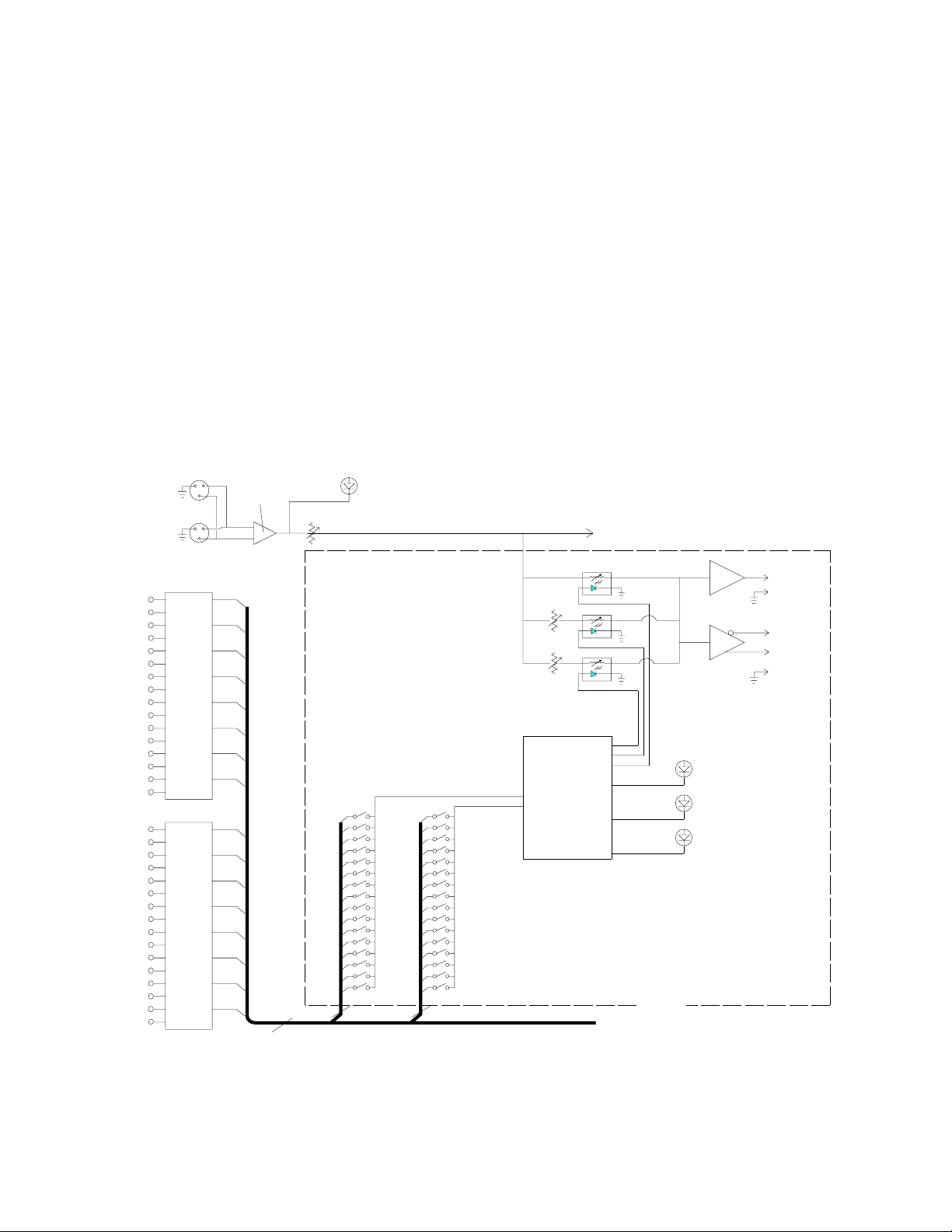
In the following illustration is a simplified block diagram of the LCA16 showing one amplifier channel. All channels
are identical.
The audio input of the LCA16 is an RF filtered, electronically balanced differential amplifier. An AUDIO THRU
output is provided so the audio signal can be "daisy chained" to other devices if required. A SIGNAL PRESENT
LED on the front panel indicates the presence of signal above -20dBv. The audio signal passes through the MAIN
LEVEL control before being distributed to the output channel amplifiers. Each output channel employs a dedicated
power amplifier. The amplifiers are fully protected from short circuits, thermal overloads or highly reactive loads.
Each amplifier is individually fused, so in the event of catastrophic failure of any single channel, no other channels
will be affected. Each output channel also includes a balanced line level output which is simultaneously available to
drive external amplifiers, or other audio equipment.
The logic input signal conditioning circuits are specially designed to accept a wide variety of logic signals, ranging
from relay contact closures to TTL logic levels. Each logic input passes through a time constant circuit with
hysteresis. This guarantees minimum "signal chopping" caused by changing attenuation during pauses in speech.
Photo-conductive opto-isolators are employed to switch the level of attenuation of the audio. These devices
eliminate the abrupt audible changes that occur when hard switching is used.
Figure 1 - LCA16 Block Diagram
2
Page 4

CONTROLS AND FUNCTIONS - FRONT PANEL
0
1
2
3
4
5
6
7
8
9
LECTROSONICS, INC.
LOGIC CONTROLLED AMPLIFIER
AUTOMATIC SPEAKER / LINE OUTPUT CONTROL
PO W E R
SI G N AL
PR ESEN T
PO W E R
MA I N L EVEL
10
ATTE NUATION MODE
LCA16
CH . 3
ON A B
ATTE NUATI ON
CH. 4
ON A B
A TTE NU A TIO N
CH. 7
ON A B
ATTENU ATIO N
CH. 8
ON A B
ATTE NUA T ION
CH. 11
ON A B
ATTE NUATIO N
CH. 1 2
ON A B
ATTE NUA TIO N
CH. 14
ON A B
ATTE NUATIO N
CH. 16
ON A B
ATTE NUA TIO N
ON A B
ATTENUA TI ON
CH . 1
ON A B
ATTE N UA T IO N
CH. 2
ON A B
ATT E NUAT IO N
CH. 5
ON A B
ATTENUATION
CH. 6
ON A B
ATTE NUATIO N
CH. 9
ON A B
ATTE NUATI ON
CH. 1 0
ON A B
ATTE NUA T I ON
CH. 13
ON A B
ATTE NUAT ION
CH. 15
POWER SWITCH
Controls the application of AC power to the LCA16.
POWER LED
Indicates the presence of AC power to the LCA16.
MAIN LEVEL
Controls the overall output level of the sound system.
SIGNAL PRESENT LED
Indicates the presence of audio signal to the LCA16.
ON LED
(Channels 1-16) Indicates the output channel is in the "on" state (not attenuated).
ATTENUATION LEDS
A LED: (Channels 1-16) Indicates the output channel is at the "A" attenuation level.
B LED: (Channels 1-16) Indicates the output channel is at the "B" attenuation level.
Figure 2 - LCA16 Front Panel
3
Page 5

ATTENUATION DIP SWITCHES (located behind front panel cover)
SWITCH
NUMBERS
ATTENUATION CONTROL POTS
3A
1
1
1
0
5
1
1
2
2 2
9
2
2
3
O
3
O
3
15
O
3
O
3
P
P
P
P
E
E
E
E
DIP SWITCHES
4 4 4
4
4
N
5
5
N
5
3B
N
5
N
5
6
6 6
6
6
0
5
9
7
7 7
7
7
8 8 8
15 8
8
9
1
1
0
5
1
1
10
2
2
9
2
2
11
O
3
O
3
O
3
O
3
12
4 4
4A
4 4
15
P
P
P
P
E
E
E
E
13
N
5
N
5
N
5
N
5
0
5
4B
14
6 6
6 6
15
7 7
9
7 7
16
8 8
15
8 8
3A
1
1
0
5 1
1 1 1
1
0
5 1
1
1
3A
3A
1
1
0
3A
5 1
1
1
1
1
0
5 1
1
2
2 2
9
2
2
2
2
2
9
2
2 2
9
2
2
2
2 2
9
2
2
2
O 3O
3
15
O 3O 33O
3O 3
15
O
3O 3
3
O
3
P
O
3
15
O
3
P
O
3
3
O
P
3
O
P
3
15
O
P
3
O
P
3
P
P
P P
P P
P
P
P
4 4
P
4
4
4
4
4
4
4
E
4 4
4
E
4 4
4
E
4
E
4
4
4
E
E
E E
E
E
E
E
E
E
E
E
3B
N
N
5N 5
3B
N
5N 5
5N 5N 5
3B
N
5
N
5
5
N
5N 5
N
5N 5
5
N
5
N
5
0
3B
5
N
5
5
6 6
6
6
6
6 6
6
6
6
0
5
0
5
6 6
0
5
6
6
6 6
6
6
6
9
9
7 7
9
7
7
7 7
7
9
7
7
7 7
7
7
7
7 7
7
7
7
8 8
15
8
8
8
8
8
15
8
8
8 8
15
8
8
8 8 8
15
8
8
8
1
1
0
5
1
1
9
1
1
051
1
9
1
1
0
5
1
1
9
1
1
051
1
2 2
9
2
2
10
2
2
9
2 2 10
POWER
2
2
9
2 2 10
2 2
9
2 2
O
O 3 O 3
O
3O 3
O 3O
3
11
O
3
O
3
15
O
3O 3 11
O
3
O
3
15
O
3O 3
11
O 3 3
15
P
P
P
P
P
15
P
P
P
P
P
P
P
4
P
4
4A
P
4
P
4 12
P
4
E
4
4A
E
4E 4
4 4
4A
E
4
E
4
12
4
E
4
4A
E
4E 4
12
E
E
E E E
5N5
N
N
5 N 5
N
5
N 5
13
N
5N5
N
5N5 13
N 5
N
5N5 13
N
0
N
E
E
E
5 5
N
5
5
6
7
8
5
9
15
4B
0
6
7
8
6
7
8 16
15
14
6
7
8
6
7
8
5
9
15
4B
0
6
7
8
6
7
8
16
15
146
7
8
6
7
8
5
9
15
4B
0
6
7
8
6
7
8
16
15
14
6
7
8
6
7
8
9
15
4B
6
7
8
6
7
8
6
7
8
POWER
SIGNAL
PRESENT
1
2
3
4
5
6
7
8
O
P
E
N
5
9
15
3A
5
9
15
3B
3A 3B
4A 4B
0
0
ATTENUATION LEVEL
1
2
3
4
5
6
7
8
O
P
E
N
1
2
3
4
5
6
7
8
O
P
E
N
1
2
3
4
5
6
7
8
O
P
E
N
1
2
3
4
5
6
7
8
O
P
E
N
O
P
E
N
1
2
3
4
5
6
7
8
ATTENUATION LEVEL
1
2
3
4
5
6
7
8
5
9
15
3A
5
9
15
3B
0
0
O
P
E
N
1
2
3
4
5
6
7
8
O
P
E
N
1
2
3
4
5
6
7
8
1
2
3
4
5
6
7
8
O
P
E
N
O
P
E
N
1
2
3
4
5
6
7
8
ATTENUATION LEVEL
1
2
3
4
5
6
7
8
5
9
15
3A
5
9
15
3B
1
2
3
4
5
6
7
8
0
0
1
2
3
4
5
6
7
8
O
P
E
N
1
2
3
4
5
6
7
8
O
P
E
N
O
P
E
N
O
P
E
N
1
2
3
4
5
6
7
8
ATTENUATION LEVEL
1
2
3
4
5
6
7
8
5
9
15
3A
5
9
15
3B
0
0
O
P
E
N
1
2
3
4
5
6
7
8
O
P
E
N
1
2
3
4
5
6
7
8
0
1
2
3
4
10
5
6
7
8
9
O
P
E
N
O
P
E
N
1
2
3
4
5
6
7
8
5
9
15
5
9
15
4A
4B
0
0
1
2
3
4
5
6
7
8
O
P
E
N
O
P
E
N
1
2
3
4
5
6
7
8
16
15
14
13
12
11
10
9
1
2
3
4
5
6
7
8
O
P
E
N
O
P
E
N
1
2
3
4
5
6
7
8
5
9
15
5
9
15
4A
4B
0
0
1
2
3
4
5
6
7
8
O
P
E
N
O
P
E
N
1
2
3
4
5
6
7
8
16
15
14
13
12
11
10
9
1
2
3
4
5
6
7
8
O
P
E
N
O
P
E
N
1
2
3
4
5
6
7
8
5
9
15
5
9
15
4A
4B
0
0
1
2
3
4
5
6
7
8
O
P
E
N
O
P
E
N
1
2
3
4
5
6
7
8
16
15
14
13
12
11
10
9
1
2
3
4
5
6
7
8
O
P
E
N
O
P
E
N
1
2
3
4
5
6
7
8
5
9
15
5
9
15
4A
4B
0
0
1
2
3
4
5
6
7
8
O
P
E
N
O
P
E
N
1
2
3
4
5
6
7
8
1
2
3
4
5
6
7
8
MAIN LEVEL
LOGIC CONT ROLLED A MPLIFIER.
LECTROSONICS, INC
These switches are used to programs which microphone (or microphones) connected to the 16 LOGIC INPUTS will
trigger the "A" and "B" attenuation levels for each of the 16 output channels. Four banks of switches (eight
switches per bank) are allocated to each channel. Two of the switch banks (16 switches) trigger the "A" attenuation
level, the other two switch banks trigger the "B" attenuation level. The switch number is printed on the circuit board
alongside the switch assemblies (disregard the numbers printed on the switch assembly itself).
ATTENUATION LEVEL CONTROLS (located between the DIP switch assemblies)
These control the amount of "A" and "B" level attenuation for each output channel. "A" level attenuation always
takes priority over "B" level attenuation and, therefore, the "A" control must always be set to a higher setting than
the "B" control.
An enlarged view of the speaker #7 and #8 sections of the attenuation selection DIP switches and attenuation level
controls is shown below. The attenuation select switches provide the means to select which microphones will
attenuate each speaker and to what attenuation level. The output of each speaker amplifier may be attenuated
from 0dB to completely off by means of the two continuously variable preset adjustment potentiometers ("A" and
"B"). Therefore, each speaker may be attenuated by one or more microphones on either (or both) of the "A" or "B"
levels as shown in the examples on page 7 and 8.
Figure 3 - Dip Switch Detail
4
Page 6
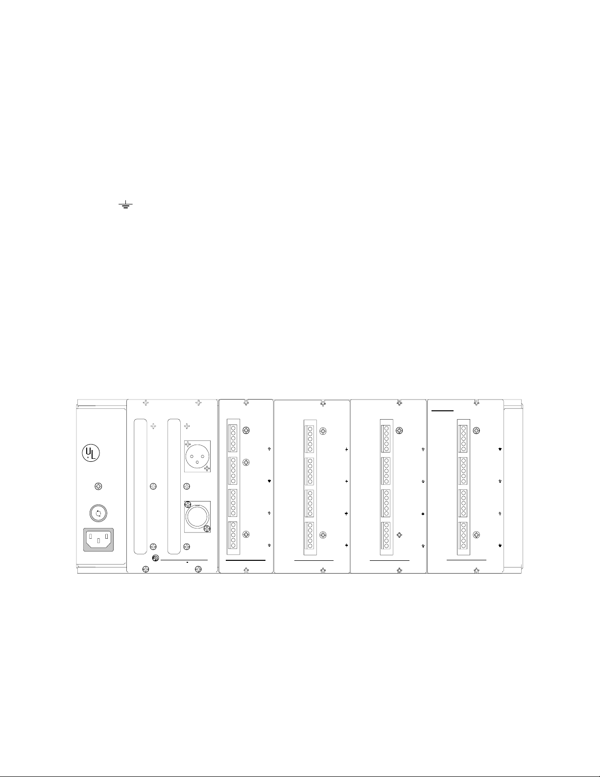
CONTROLS AND FUNCTIONS - REAR PANEL
SPKR OUT
Connects to the individual speakers in the sound system. SPKR OUT (+) is the "hot" terminal, and SPKR OUT (-)
is ground.
LINE OUT +/-
Provides balanced line level drive to external amplifiers or other equipment. The LINE OUT signal is attenuated
identically to its associated speaker output. Output impedance is 600 ohms, and is suitable for driving both low and
high impedance inputs.
LINE OUT
Provides the ground connection for the balanced line driver.
LOGIC INPUTS
Connects to the logic outputs of an automatic mixer, or to other types of contact closure. Logic Input (+) connects
to the (+) terminal of logic output on an automatic mixer, and the Logic Input (-) is ground.
AUDIO INPUT
Receives the audio signal for the sound system. This input is electronically balanced and RF filtered, and uses a
standard 3 pin XLR female connector.
AUDIO THRU
Outputs the signal received by the Audio Input for daisy chaining applications. This output is directly in parallel with
the AUDIO INPUT.
FUSE
Protects the unit in case of internal overload. Replace only with a 1.5 amp slow blow fuse.
SER NO
LECTROSONICS, INC.
RIO RANCHO, NM - USA
WARNING
TO REDUCE THE RISK OF FIRE
OR ELECTRIC SHOCK, DO NOT
EXPOSE THIS EQUIPMENT TO
RAIN OR MOISTURE.
LISTED
COMMERCIAL
AUDIO
EQUIPMENT
R
4L01
US PATENT PENDING
CAUTION
TO REDUCE THE RISK OF FIRE,
REPLACE ONLY WITH SAME TYPE
1 1/2A, 250V "SLO-BLO" FUSE.
F
E
U
S
S
E
U
F
F
U
S
E
120V AC
200 WATTS
TO REDUCE THE RISK OF ELECTRIC SHOCK, DO
NOT REMOVE COVER. NO USER SERVICEABLE
PARTS INSIDE. REFER SERVICING TO.
QUALIFIED SERVICE PERSONNEL.
+
9
-
L
+
10
O
G
+
11
I
C
+
12
-
+
13
-
+
14
-
+
15
-
+
16
-
CAUTION
+
1
-
2
-
3
-
+
4
-
+
5
-
I
+
N
6
-
P
U
+
7
T
-
S
AUDIO THRU
+
8
-
LECTROSONICS, INC.
AUDIO INPUT
MADE IN USA RI O RA NCHO , NM
13
14
15
16
AM 4
LCA16 OU TP UT MODU L E
SER NO
SPKR
SPKR
LINE OUT
LINE OUT
LINE OUT
SPKR
SPKR OUT
LINE OUT
LINE OUT
LINE OUT
SPKR
SPKR
LINE OUT
LINE OUT
LINE OUT
SPKR
SPKR
LINE OUT
LINE OUT
LINE OUT
SER NO
+
OUT
-
OUT
+
-
+
OUT
-
+
-
+
OUT
-
OUT
+
-
+
OUT
-
OUT
+
-
9
10
11
12
AM 4
LC A16 OUT P UT MODULE
SPKR OUT
SPKR OUT
LINE OUT
LINE OUT
LINE OUT
SPKR
SPKR
LINE OUT
LINE OUT
LINE OUT
SPKR OUT
SPKR
LINE OUT
LINE OUT
LINE OUT
SPKR
SPKR
LINE OUT
LINE OUT
+
-
5
+
-
+
OUT
-
OUT
+
-
OUT
+
-
+
OUT
-
OUT
+
-LINE OUT
+
-
6
7
8
AM 4
LCA16 OU TP UT MODU L E
SER NO
SPKR OUT
SPKR OUT
LINE OUT
LINE OUT
LINE OUT
SPKR OUT
SPKR
LINE OUT
LINE OUT
LINE OUT
SPKR OUT
SPKR OUT
LINE OUT
LINE OUT
LINE OUT
SPKR
SPKR OUT
LINE OUT
LINE OUT
LINE OUT
+
-
+
-
+
-
OUT
+
-
+
-
+
-
+
OUT
-
+
-
Figure 5 - LCA16 Rear Panel
SP KR OUT: O HMS
5W R M S @ 4 O H M S
3. 5 W R M S @ 8 O H M S
LI NE OUT:
60 0 OHM B ALANCED
AM 4
LCA16 OU TP U T MOD U L E
1
2
3
4
SER NO
CL A S S 2 WIRING
M A Y B E U S ED
OUT
SPKR
OUT
SPKR
LINE OUT
LINE OUT
OUT
SPKR
OUT
SPKR
LINE OUT
LINE OUT
SPKR OUT
SPKR OUT
LINE OUT
LINE OUT
LINE OUT
SPKR OUT
SPKR OUT
LINE OUT
LINE OUT
LINE OUT
+
-
+
-LINE OUT
+
-
+
-LINE OUT
+
-
+
-
+
-
+
-
5
Page 7

PRE-CONFIGURING THE LCA16 PRIOR TO INSTALLATION,
16 or FEWER MICS PER LCA16
This procedure should be performed prior to installation. The LCA16 SYSTEM WORKSHEET (Appendix 2) will
assist you in setting up the LCA16 before going on site. While the actual setup is quite simple, it is recommended
that you use this worksheet, especially if this is your first installation using the LCA16 Logic Controlled Amplifier.
Using the LCA16 SYSTEM WORKSHEET
PROCEDURE 1 - Use this procedure if you have 16 or fewer microphones per LCA16 in this installation. This
procedure assumes a 1:1 relationship between microphones and logic terminals. If you have more than 16
microphones per LCA16, then skip this section and use procedure 2.
To fill out this chart, you need a floor plan of the room showing both speaker and microphone placement. See
below for an example of a floor plan with notations showing mics, speakers, and attenuation zones.
STEP 1 - On your floor plan, assign consecutive numbers to each microphone, starting with #1.
STEP 2 - Assign consecutive numbers to each speaker on the floor plan, again starting with #1.
STEP 3 - On your LCA16 SYSTEM WORKSHEET, assign the microphones to logic inputs in the first column on
the left. Simply transfer the microphone numbers from your floor plan to the crossed boxes. See
Example 1.
STEP 4 - Assigning Attenuation Levels In this step you will be noting in each box how much the speakers will
be affecting each microphone.
4A Start with the box where the SPEAKER 1 column intersects the microphone 1 (logic input 1) row. Check you
floor plan. If speaker 1 will be a potential source of feedback for microphone 1, then mark that box. Use an
"A" for speakers which are very close to the microphone and a "B" for those which are located further from
the microphone. While still referring to the floor plan, move down to the next box in the speaker 1 column
where it intersects the microphone 2 row. If speaker 1 will also affect microphone 2, then mark that box
accordingly.
If this speaker will have no effect, then leave the box blank.
4B Repeat this step for every box in the grid where a speaker and microphone/logic input intersect.
A LEVEL ATTENUATION ZONE FOR MIC 1
B LEVEL ATTENUATION ZONE FOR MIC 1
SPEAKER
A
B
STEP 4
1
TABLE
EXCERPT FROM
ROOM PLAN
SPKR
1
SPKR
2
2
SPEAKER
MICROPHONE
CHAIR
3
STEP 3
1 2 3 4
Assigned
Mics
1
1
A B B
2
2
3
3
Figure 6 - Example 1
6
Page 8

STEP 5 - Setting the DIP switches Upon completion of the chart you will have a grid which can now be used for
setting the DIP switches on the LCA16. See Example 2 below. Each speaker output on the LCA16 has a
set of dip switches on the front panel. There are two banks of 16 switches aligned vertically above a set of
LED indicators. The left bank of switches is for "A" level attenuation. The right bank of switches is for "B"
attenuation. DIP switches are set to the ON position by depressing them to the right. You will set these
switches according to the A and B notations on your LCA16 SYSTEM WORKSHEET.
For example, according to the worksheet in Example 2, speaker 1 has two microphones which it affects.
Speaker 1 will need to be attenuated to "A" level for microphone 1 and attenuated to "B" for microphone
2.
Speaker 2 will need to be attenuated to "B" level for microphones 1 and 3 and attenuated to "A" level for
microphone 2.
The illustrations below indicate how the switches will need to be set according to the worksheet.
DOT INDICATES "ON" CONDITION.
7A 7B 8A 8B
1
2
3
OPEN OPEN
4
5
6
7
8
9
10
11
12
13
14
15
16
OPEN OPEN
5
0
9
15
7A
7B
5
0
9
15
5
0
9
15
OPENOPEN
8A
8B
5
0
9
15
OPENOPEN
1
2
3
LOGIC
Assigned
1
2
3
Mics
1 2 3 4
A B
B A
B
SPEAKER
Figure 7 - Example 2
STEP 6 - Make your initial settings for the "A" and "B" levels of attenuation. If you have not yet determined a starting
level of attenuation for your speakers, it is suggested that all "A" levels be set for full attenuation (completely
off) and the "B" levels set for 5 to 9dB of attenuation. PLEASE NOTE THAT THE "A" LEVEL WILL
ALWAYS TAKE PRIORITY OVER "B" LEVEL, SO BE CERTAIN THE "A" LEVEL IS SET TO THE
GREATER ATTENUATION.
The levels of attenuation are set by adjusting the small recessed pots found between each pair of output
channel DIP switches located on the front panel. See the illustration above. These controls are set with a
small screwdriver (provided with the LCA16). Fully clockwise sets the channel to completely off. Set all
active channels.
The LCA16 is now pre-configured and may be installed in the rack. Proceed to page 10, INSTALLATION.
7
Page 9

PRE-CONFIGURING THE LCA16 PRIOR TO INSTALLATION,
MORE THAN 16 MICS PER LCA16
PROCEDURE 2 - Use this procedure for those installations where there are more microphone channels than logic
inputs.
The only difference between this setup and the setup described previously is that you have assigned multiple
microphones to the same logic input because they are affected by the same group of speakers. This practice
is only necessary when the number of microphones exceeds the number of logic inputs in the installation.
Using the LCA16 SYSTEM WORKSHEET
To fill out this chart, you will need a floor plan of the room showing both speaker and microphone placement. See
below for an example of a floor plan with notations showing mics, speakers, and attenuation zones.
STEP 1 - On your floor plan, assign consecutive numbers to each microphone, starting with #1.
STEP 2 - Assign Consecutive numbers to each speaker on the floor plan, again starting with #1.
STEP 3 - This step is critical for assigning multiple microphones to the same logic input. As you look at your floor plan,
check to see which microphones will be affected by exactly the same speakers. These microphone channels
can be wired to the same logic inputs. For example, if microphones 1 and 2 are both affected by the same
speaker, then you can assign both mics to logic input 1 (see Example 3). These logic input assignments will
assist you when wiring the twisted pair wires from your logic connections on the automatic mixer to the logic
connections on the LCA16. Repeat this step for each group of microphones.
STEP 4 - Assigning Attenuation Levels. In this step you will be noting in each box how much the speakers need to
be attenuated.
4A Start with the box where the SPEAKER 1 column intersects the logic input 1 row. Check your floor plan. If
the speaker 1 will be a potential source of feedback for microphone 1, then mark that box. Us an "A" for
speakers which are very close to the microphone and a "B" for those which are located further from the
microphone. While still referring to the floor plan, move down to the next box in the speaker 1 column (where
it intersects with logic input 2). If speaker 1 may also be a source of feedback for the mics assigned to logic
input 2, then mark that box accordingly.
If it is unlikely that feedback will occur, then leave the box blank.
4B Repeat this step for every box in the grid where a microphone/logic input row and a speaker column
intersect.
A LEVEL ATTENUATION ZONE FOR MIC 1
1 2
1
TABLE
EXCERPT FROM
ROOM PLAN
2
3
SPEAKER
MICROPHONE
B LEVEL ATTENUATION ZONE FOR MIC 1
CHAIR
4
5
STEP 3
Assigned
1
1
3
2
5
3
Figure 8 - Example 3
8
SPEAKER
1
2 3 4
Mics
A
2
4
B
A
B
B
STEP 4
Page 10

STEP 5 - Setting the DIP switches Upon completion of the chart you will have a grid which can now be used for
setting the DIP switches on the LCA16. See Example 4 below. Each speaker output on the LCA16 has a
set of DIP switches on the front panel. There are two banks of 16 switches aligned vertically above each
LED bank. The left bank of switches is for "A" level attenuation. The right bank of switches is for "B"
attenuation. DIP switches are set to the ON position by depressing them to the right. You will set these
switches according to the notations written on your LCA16 WORKSHEET.
For example, according to the worksheet in Example 4, speaker 1 is attenuated by two logic inputs.
Speaker 1 will need maximum attenuation ("A" level) for logic input 1 (microphones 1 and 2) and partial
attenuation ("B" level) for logic input 2 (microphones 3 & 4).
Speaker 2 will need to be attenuated partially ("B" level) for logic inputs 1 and 3 and fully attenuated ("A"
level) for logic input 2.
The illustrations below show how the switches will need to be set according to the chart.
DOT INDICATES "ON" CONDITION.
7A 7B 8A 8B
1
2
3
OPEN OPEN
4
5
6
7
8
9
10
11
12
13
14
15
16
OPEN OPEN
5
0
9
15
OPEN OPEN
7A
7B
5
0
9
15
5
0
9
15
8A
8B
5
0
9
15
OPEN OPEN
1
2
3
LOGIC
Assigned
1
2
3
Mics
1 2 3 4
BA
B A
B
SPEAKER
Figure 9 - Example 4
STEP 6 - Make your initial settings for the "A" and "B" levels of attenuation. If you have not yet determined a starting
level of attenuation for your speakers, it is suggested that all "A" levels be set for full attenuation (completely
off) and the "B" levels set for 5 to 9dB of attenuation. PLEASE NOTE THAT THE "A" LEVEL WILL
ALWAYS TAKE PRIORITY OVER "B" LEVEL, SO BE CERTAIN THE "A" LEVEL IS SET TO THE
GREATER ATTENUATION.
The levels of attenuation are set by adjusting the small recessed pots found between each pair of output
channel DIP switches located on the front panel. See the illustration above. These controls are set with a
small screwdriver (provided with the LCA16). Fully clockwise sets the channel to completely off.
The LCA16 is now pre-configured and may be installed in the rack. Proceed to page 10, INSTALLATION.
9
Page 11

INSTALLATION
The LCA16 is designed to be mounted in a standard 19-inch equipment or cabinet. Adequate ventilation must be
provided which can normally be accomplished by leaving at least two open rack spaces (3 1/2 inches) above and below
the unit. Generally, the LCA16 should be positioned such that the intake air (from the bottom of the unit) is the coolest
available in the rack. If there are fans in the rack for cooling, optimum placement will be determined by the fan position.
INTERCONNECTIONS
Refer to your LCA16 SYSTEM WORKSHEET to see which microphone is connected to each LOGIC INPUT, and
which speaker is connected to which output channel. Your room sketch will also be helpful. Number each
speaker and microphone and tag the wire pairs. Doing this prior to making any interconnections will save a
great deal of time during the initial setup. It is not necessary to install microphones and speakers in any
particular order.
Audio Connection from Mixer / Signal Processor
Electrical connection to the AUDIO INPUT is made using a standard 3-pin XLR type connector. Pin 2 is audio "hot" (+),
pin 3 is audio "cold" (-), and pin 1 is ground (shield). If an unbalanced source is used for audio input, connect the
source ground to pins 1 and 3 at the LCA16, and source "hot" to pin 2. The use of a two-wire plus shield cable is
recommended, with the shield left unconnected at the source end and connected to signal ground at the LCA16 end
regardless of whether the source is balanced or unbalanced.
Logic Connections From Mixer
Electrical connection to the LOGIC INPUTS is made using stripped and tinned insulated hookup wire, 18 to 24 gauge. If
connecting to Lectrosonics’ AP4 Modular Audio Processor modules, simply connect the LOGIC OUT (+) of the AP4 to
the LOGIC INPUT (+) of the LCA16, and the LOGIC OUT (-) of the AP4 to the LOGIC INPUT (-) of the LCA16. If
multiple microphones are assigned to the same logic input, the logic connections may be connected in parallel.
If connection is being made to relay contacts, the polarity of the connection is unimportant. When connecting to the logic
outputs of other manufactures’ equipment, treat the LOGIC INPUT (-) on the LCA16 as "ground" and the LOGIC INPUT
(+) on the LCA16 as "signal" or "hot". Internally, the LOGIC INPUT (+) on the LCA16 is connected through 100k Ohm
to +5 Volts, so any logic output or other contact system which is interfaced to the LCA16 must be capable of sinking 50
microamps of continuous current. The LOGIC INPUTS of the LCA16 are active low.
Speaker Connections
Electrical connections to the SPKR OUT terminals are made using any two wire cable of 22 gauge or larger. Refer to
the table in Appendix 1 for power loss vs cable distance data. The best practice is to tin the leads before insertion into
the terminal blocks to eliminate wire "whiskers" that might cause intermittent connections. The SPKR OUT terminals
drive low impedance loads (4 Ohms and above) directly, making a matching transformer at the speaker unnecessary.
The SPKR OUT + output terminal is in phase with pin 2 of AUDIO INPUT. The SPKR OUT - terminal is connected to
system ground. Neither of the output terminals should be connected to any other grounds (e.g. building grounds, cold
water grounds, etc.) or to any source of voltage. The only connections that should be made are to the speaker itself.
Line Out to Recorder or External Amplifier
Electrical connections to the LINE OUT terminals can be made in one of two ways, depending on whether a balanced or
unbalanced input is to be driven. In both cases a two-wire plus shield type of cable should be used. For driving a
balanced input, LINE OUT + connects to the signal "hot" (pin 2 on a standard XLR 3-pin connector), and LINE OUT -
connects to the signal "cold" (pin 3 on a standard XLR 3-pin connector). LINE OUT is connected to the shield of
the cable. It is not necessary to connect the shield to anything at the other end of the cable. The connection at the
LCA16 end is sufficient for shielding.
With a balanced system, there is no need to connect the grounds together. An additional benefit of this is that the
possibility of ground loops will be eliminated. For driving an unbalanced input, LINE OUT + is connected to the "signal"
terminal of the input to be driven, and the LINE OUT is connected to the "ground" terminal of the input. Note that
both "signal" and "ground" should be carried on the two wires of the cable. The shield should be connected to LINE
OUT on the LCA16 end and left unconnected on the other end.
10
Page 12

INTERCONNECTION DIAGRAM
LOUDSPEAKERS
LOGI C OUTPUTS
LOGI C OUTPUTS
LOGI C OUTPUTS
-
+
GND
RT N
SND
SN D
RT N
GND
+
-
-
+
GND
RT N
SN D
LOGIC OUTP UTS
SN D
RTN
GN D
+DC
-DC
MIC INPUT 1
MIC INPUT 2
MIC INPUT 3
MIC IN PUT 4
AUTOM ATIC MICROP HON E PR EAM P
70V DISTRIBUTED SYSTEM
TO MICROPHONES
FROM AUDIO OUTPUT OF MIXER
AUTOMATIC
MICROPHONE
MIXER
TWISTED PAIR
LOGIC
CONNECTIONS
LINE
SPEAKER
LEVEL
OUTPUTS
LISTED
COMMERCIAL
AUDIO
EQUIPMENT
4L01
120V AC
200 WATTS
US PATENT PENDING
R
MADE IN USA RIO RAN CHO, NM
LECTROSONICS, INC.
S
T
U
P
N
I
AUDIO THRU
8
7
6
5
16
15
14
13
-
+
-
+
-
+
-
+
-
+
-
+
-
+
-
+
AUDIO INPUT
C
I
G
O
L
-
+
-
-
-
+
-
-
-
4
3
2
1
12
10
9
-
+
9
10
11
12
SP KR
OUT
+
-
LINE OUT
SP KR O U T
+
-
LINE O UT
LINE O UT
LCA 16 OUTPUT MODULE
AM 4
13
14
15
16
SP KR
OU T
+
-
LINE OUT
SP KR
OUT
+
-
LINE O U T
LINE OUT
SP KR O U T
+
-
LINE O U T
SP KR
OUT
+
-
LINE O U T
LINE O U T
SP KR
OU T
+
-
LINE OUT
SP KR O U T
+
-
LINE O U T
LINE O U T
LCA 16 O UT PUT M ODU
AM 4
SER NO
+
+
+
11
EXTERNAL
AMPLIFIER
LCA 16 LOGIC CONTROLLED AMPLIFIER
F
U
S
E
F
U
S
E
F
U
S
E
LEVEL
OUPUTS
Figure 13 - Interconnection Diagram
11
Page 13

ATTENUATION SETTINGS
AND SPEAKER SYSTEM ADJUSTMENTS
The steps and procedures in this section should be followed only after all wiring and audio connections have been
completed, and the system components have been installed. It is also necessary to complete the worksheet for speaker
attenuation and the pre-configuration instructions for the LCA16 before attempting the adjustments in this section.
MAIN LEVEL ADJUSTMENT ON THE LCA16
The pre-configuration instructions on pages 6 through 9 simply provide a "starting point" for further adjustment. The
settings suggested in that section are based upon typical experience gathered from the field. The actual settings for a
particular system may vary from these settings once the final set up is completed.
Ideally, the LCA16 should provide just enough attenuation to prevent feedback while allowing maximum speaker system
coverage. Attenuation beyond what is necessary for feedback control can make the operation of the LCA16 audible as
the speaker system attenuates in response to microphone activity. In many installations, the operation of the sound
system is almost transparent. In other words, the talkers do not actually hear themselves over the speaker system as
they talk, yet adequate reinforcement is provided so that more distant listeners can hear them clearly.
The first step in the final set up is to complete the attenuation settings for a single speaker zone, and then use these
settings as a guide for subsequent adjustments. The final adjustment of this first speaker zone will provide a setting for
the LCA16 MAIN LEVEL control. Once the MAIN LEVEL control is set for the first speaker zone, it should be left alone
for adjustment of the rest of the speaker zones.
Select a zone in the central part of the room and activate a microphone within it. Gradually increase the MAIN LEVEL
on the LCA16 until an adequate volume is achieved. If feedback occurs before adequate gain can be achieved,
increase the attenuation level of the speakers near the open microphone and then continue to increase the sound
system level. If additional attenuation is required, it often requires a change in the DIP switch settings indicated by the
original worksheet (more speakers may need to be attenuated). Activate each microphone in this zone (if there is more
than one) and check for adequate gain. Re-adjust the attentuation levels as needed.
If adequate gain cannot be achieved, even with excessive speaker attenuation, the basic sound system design may
be at fault. In this case, it may be time to re-evaluate the mouth to microphone distances and/or the basic microphone
and speaker system layout in the room.
If there is more than enough gain, reduce the amount of attenuation of the speakers near the open microphone.
Remember that the most transparent operation will be achieved with the least amount of attenuation. Use only enough
attenuation to control feedback.
Once adequate gain is achieved on the first zone, leave the MAIN LEVEL control on the LCA16 alone for adjusting the
remaining channels.
SETTING ATTENUATION LEVELS ON REMAINING CHANNELS
With the LCA16 MAIN LEVEL control set for the first zone (see above), repeat the above procedure for each of the
remaining speaker zones. Be sure to check all microphones in each speaker zone as you proceed.
AUTOMATIC MIXER THRESHOLD ADJUSTMENT
If the sound system (loudspeakers) open unused microphone channels during the adjustment process, increase the turnon threshold setting on the automatic mixer just enough to keep the unused channels from turning on. This control is
labeled THRESHOLD on the Lectrosonics AC1 controller.
12
Page 14

Audio Input:
Connectors: 3-pin female XLR, electronically balanced and RF filtered
Impedance: 20K Ohms balanced, 10K Ohms unbalanced
Max Input Level: +8dBv
Thru Output:
Connectors: 3-pin male XLR, parallel with Audio Input
Logic Input:
Connectors: Terminal Strip
Impedance: 100K Ohms in parallel with 2.2uF pulled up to +5 volts
Speaker Output:
Connectors: Terminal Strip
Load Impedance: 4 Ohms or greater
Protection: Short circuit
THD (20Hz-20KHz): Less than .25% @ 5 watts, 4 Ohms (80KHz filter)
IMD (60Hz/7KHz): Less than .25% @ 5 watts, 4 Ohms (80KHz filter)
Noise (20Hz-20KHz): Less than -75dBv (Gain control at unity)
SPECIFICATIONS
Open circuit
Thermal
Excessively reactive load
Line Output:
THD (20Hz-20KHz): Less than .05% @ 4dBv
IMD (60Hz/7KHz): Less than .05% @ 4dBv
Noise (20Hz-20KHz): Less than -90dBv
Attenuation Method: Automatic Rated-controlled Variable Attenuation*
Power Consumption: 160 Watts maximum
* US PATENT NUMBER 5204908
13
Page 15

SERVICE AND REPAIR
If your system malfunctions, you should attempt to correct or isolate the trouble before concluding that the equipment
needs repair. Make sure you have followed the setup procedure and operating instructions. Check out the interconnecting cords and then go through the TROUBLE SHOOTING section in the manual
We strongly recommend that you do not try to repair the equipment yourself and do not have the local repair shop
attempt anything other than the simplest repair. If the repair is more complicated than a broken wire or loose
connection, send the unit to the factory for repair and service. Don’t attempt to adjust any controls inside the units.
Once set at the factory, the various controls and trimmers do not drift with age or vibration and never require
readjustment. There are no adjustments inside that will make a malfunctioning unit start working.
LECTROSONICS service department is equipped and staffed to quickly repair your equipment. In-warranty repairs are
made at no charge in accordance with the terms of the warranty. Out of warranty repairs are charged at a modest flat
rate plus parts and shipping. Since it takes almost as much time and effort to determine what is wrong as it does to
make the repair, there is a charge for an exact quotation. We will be happy to quote approximate charges by phone for
out of warranty repairs.
RETURNING UNITS FOR REPAIR
You will save yourself time and trouble if you will follow the steps below:
A. DO NOT return equipment to the factory for repair without first contacting us by letter or by phone. We need to
know the nature of the problem, the model number and the serial number of the equipment. We also need a phone
number where you can be reached 8 am to 4 pm (Mountain Standard Time).
B. After receiving your request, we will issue you a return authorization number (R.A.). This number will help speed
your repair through our receiving and repair departments. The return authorization number must be clearly shown
on the outside of the shipping container.
C. Pack the equipment carefully and ship to us, shipping costs prepaid. If necessary, we can provide you with the
proper packing materials. UPS is usually the best way to ship the units. Heavy units should be "double-boxed" for
safe transport.
D. We also strongly recommend that you insure the equipment, since we cannot be responsible for loss of or damage
to equipment that you ship. Of course, we insure the equipment when we ship it back to you.
Mailing address: Shipping address: Telephones:
Lectrosonics, Inc. Lectrosonics, Inc. (505) 892-4501
PO Box 15900 581 Laser Rd. (800) 821-1121
Rio Rancho, NM 87174 Rio Rancho, NM 87124 FAX: (505) 892-6243
USA USA
World Wide Web: http://www.lectrosonics.com email: sales@lectrosonics.com
14
Page 16

APPENDIX 1 - POWER LOSS vs CABLE RUN
The table below indicates power loss vs cable run for various wire gauges. Nominal output power for the LCA16 is 5
watts at 4 ohms and 3 watts at 8 ohms.
22 AWG Wire, 4 ohm load
Distance Total Power Available Load Power Wire Loss
25ft. 4.8W 4.5W .3W
50ft. 4.5W 4.0W .5W
100ft. 4.0W 3.2W .8W
250ft. 3.1W 1.9W 1.2W
18 AWG Wire, 4 ohm load
Distance Total Power Available Load Power Wire Loss
25ft. 4.9W 4.7W .2W
50ft. 4.7W 4.3W .4W
100ft. 4.4W 3.7W .7W
250ft. 3.6W 2.6W 1.0W
16 AWG Wire, 4 ohm load
Distance Total Power Available Load Power Wire Loss
25ft. 4.9W 4.8W .1W
50ft. 4.8W 4.6W .2W
100ft. 4.6W 4.2W .4W
250ft. 4.0W 3.2W .8W
22 AWG Wire, 8 ohm load
Distance Total Power Available Load Power Wire Loss
25ft. 2.9W 2.7W .2W
50ft. 2.7W 2.5W .2W
100ft. 2.5W 2.1W .4W
250ft. 2.0W 1.3W .7W
20 AWG Wire, 8 ohm load
Distance Total Power Available Load Power Wire Loss
25ft. 2.9W 2.8W .1W
50ft. 2.8W 2.6W .2W
100ft. 2.7W 2.4W .2W
250ft. 2.3W 1.7W .6W
18 AWG Wire, 8 ohm load
Distance Total Power Available Load Power Wire Loss
25ft. 3.0W 2.9W .1W
50ft. 2.9W 2.8W .1W
100ft. 2.8W 2.6W .2W
250ft. 2.5W 2.1W .4W
16 AWG Wire, 8 ohm load
Distance Total Power Available Load Power Wire Loss
25ft. 3.0W 2.9W .1W
50ft. 2.9W 2.8W .1W
100ft. 2.9W 2.7W .2W
250ft. 2.7W 2.4W .3W
15
Page 17

1
2
3
4
5
APPENDIX 2 - LCA16 SYSTEM WORKSHEET
DIPSWITCH SETTINGS
SPEAKER
Assigned
Mics
1 2 3 4 5 6 7 8 910 11 12 13 14 15 16
LOGIC INPUT
6
7
8
9
10
11
12
13
14
15
16
16
Page 18

LIMITED ONE YEAR WARRANTY
The equipment is warranted for one year from date of purchase against defects in
materials or workmanship provided it was purchased from an authorized dealer.
This warranty does not cover equipment which has been abused or damaged by
careless handling or shipping. This warranty does not apply to used or
demonstrator equipment.
Should any defect develop, we will, at our option, repair or replace any defective
parts without charge for either parts or labor. If we cannot correct the defect in
your equipment, we will replace it at no charge with a similar new item. We will
pay for the cost of returning your merchandise to you.
This warranty applies only to items returned to us, shipping costs prepaid, within
one year from the date of purchase.
This warranty gives you specific legal rights. You may have additional legal rights
which vary from state to state.
LECTROSONICS, INC.
581 LASER ROAD
RIO RANCHO, NM 87124 USA July 6, 1999
 Loading...