

Page 1

T5
MULTI-FREQUENCY IFB TRANSMITTER
EURO MODEL
OPERATING INSTRUCTIONS
and trouble-shooting guide
LECTROSONICS, INC.
www.lectrosonics.com
0885
Page 2

INTRODUCTION
Thank you for selecting the Lectrosonics frequency agile, narrowband, T5 IFB
transmitter. The T5 is the result of over 80 years of engineering experience with the
very latest components, in a design that addresses the most demanding professional applications.
The Lectrosonics T5 IFB Transmitter along with the companion R5 IFB Receiver
allow on-air talent to monitor program audio and receive cues from video directors
and other production personnel.
The design of the T5 IFB Transmitter was the direct result of numerous conversations with users, production personnel and dealers across the US. The specific
concerns and needs brought up in these conversations led directly to the development of the operational features offered on the T5. Two hundred fifty six frequencies
are user selectable in 100 kHz or 25 kHz steps to alleviate interference problems in
travelling venues. 100 kHz channel spacing is standard. 25 kHz channel spacing
can be programmed into a unit by the factory or by authorized service centers.
The T5 IFB Transmitter is a rugged, machined aluminum package. The input section
is adjustable for virtually any microphone or line level audio source. Level indicating
LEDs are provided on the control panel to make level settings quick and accurate,
without having to view the receiver. The antenna is a detachable, locking 1/4 wavelength flexible bronze cable that connects to a 50 Ohm mini-jack on the transmitter.
Only the T5 IFB Transmitter is covered in this manual. Companion receivers are
covered in separate manuals. The T5 IFB Transmitter will operate with any Lectrosonics R5 IFB Receiver in the same frequency group.
TABLE OF CONTENTS
INTRODUCTION ...................................................................................................... 2
GENERAL TECHNICAL DESCRIPTION ................................................................ 3
FRONT PANEL CONTROLS AND FUNCTIONS ................................................... 5
REAR PANEL CONTROLS AND FUNCTIONS ...................................................... 6
INSTALLATION AND OPERATION ......................................................................... 7
OPERATING NOTES ............................................................................................... 7
MODE SWITCHES AND GROUND LIFT JUMPER ............................................... 8
TROUBLESHOOTING.............................................................................................. 9
FREQUENCY BLOCKS AND RANGES ............................................................... 10
REPLACEMENT PARTS and ACCESSORIES .................................................... 10
SPECIFICATIONS AND FEATURES .................................................................... 11
WARRANTY .............................................................................................. Back cover
The T5 IFB transmitter is FCC type accepted under Part 74: 470 - 608MHz and 614 - 806MHz
2
Page 3
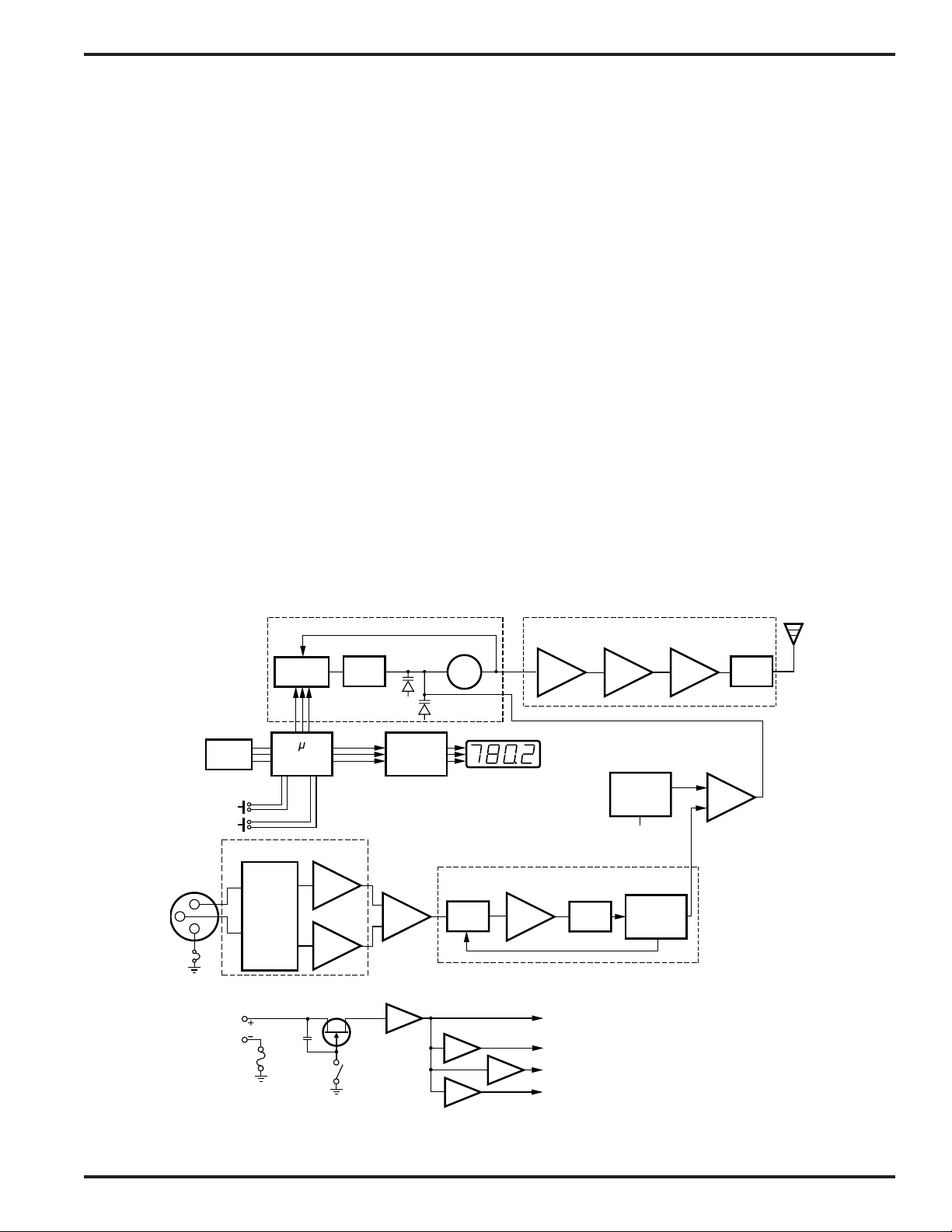
GENERAL TECHNICAL DESCRIPTION
C
IFB Transmitter
The T5 IFB Transmitter is comprised of a number of functional sub-systems as shown in the block diagram below.
GENERAL
The T5 is designed to operate with the Lectrosonics R5 IFB Receiver and features microprocessor control of 256
frequencies of operation within any one of at least thirteen frequency bands. (See page 10.)
The T5 uses 20kHz deviation for an efficient use of bandwidth. The transmitter circuits are all regulated for frequency
stability and high audio performance. The input amplifier is a discreet differential circuit which can be adjusted to
allow the use of many different input sources.
AUDIO INPUT
The input sensitivity and XLR pin functions can be customized using a clever dip switch circuit. Several different
combinations of gain and input hookup are possible without rewiring the mic connector. Pin 1 of the XLR input
connector is normally connected directly to ground but an internal jumper can be moved if a floating input is desired.
The Audio (+) and (–) are “dry” inputs and can each withstand +/- 50Vdc. Direct connection to a phone line can
damage the inputs.
AUDIO PROCESSOR
The Audio Processor section has several functions. Audio limiting is accomplished in the Shunt Limiter while the
Bandpass filter limits the audio bandwidth to 100Hz at the low end and 10kHz in the upper range. The single band
compandor circuit is one half of a system that requires a matching receiver to decode the signal and restore it to its
original dynamic range.
Frequency Synthesizer
Serial
Control
Input
Amplifier
Circuit
Power
On/Off
LP
Filter
VCO
Display
Driver
Audio Processor
Shunt
Limiter
PLL &
Prescaler
Memory
Down
XLR
Input
onnector
2
3
1
Input
Power
11-18 VDC
Polyfuse
Up
Audio Input Interface
FREQ
Controller
Mode
Set
Switches
Power Delay
Transmitter
Buffer
100Hz-10kHz
+10V
+5V
+5.5V
+6V
BP
Filter
PreAmp
Pilot Tone
Oscillator
Power
Control
Compandor
Amp
Filter
Output
Amp
T5 IFB Transmitter Block Diagram
Rio Rancho, NM – USA
3
Page 4

GENERAL TECHNICAL DESCRIPTION
COMPANDOR NOISE REDUCTION
The single band compandor is a high quality audio device that processes the input signal such that the large dynamic ranges of input signal can be transmitted to the receiver without overload or noise. A complementary system
in the receiver recovers the original dynamics of the signal for full audio quality. Compression and expansion ratios
are complementary at 2:1. High frequency pre-emphasis is implemented in the transmitter to provide another 10dB
signal to noise improvement. Matching de-emphasis is provided in all receivers.
PILOT TONE
The T5/R5 system utilizes an ultrasonic tone modulation of the carrier to operate the receiver squelch. This “pilot
tone” consists of a 29.997kHz signal mixed with the audio signal, just after the compandor, to control the audio
output muting of the receiver. The pilot tone is filtered out of the audio signal immediately after the detector in the
receiver so that it does not influence the compandor or various gain stages.
The basic benefit of the pilot tone squelch system is that the receiver will remain muted until it receives the pilot tone
from the matching transmitter, even if a strong RF signal is present on the carrier frequency of the system. This is
extremely important in applications that include an automatic microphone mixer.
FREQUENCY AGILITY
The transmitter uses a synthesized, frequency selectable main oscillator. The frequency is extremely stable over a
wide temperature range and over time. Two push-button switches, located on the front panel of the unit, provide 256
frequencies in 100 kHz or 25 kHz steps over a 25.5 MHz range. This alleviates carrier interference problems in
mobile or travelling applications.
MICROCONTROLLER
Frequency adjustment and display are handled by the microprocessor. Nonvolatile memory is provided for holding
the last frequency used even if power is removed from the unit for any length of time. Each time the transmitter is
powered up it will display the last frequency used.
TRANSMITTER
The T5 transmitter operates at 50mW*. The transmitter circuits are buffered and filtered for exceptional spectral
purity. The extra clean signal that results reduces the chances for interference between multiple transmitter installations.
ANTENNA
At UHF frequencies, where wavelengths and antennas are shorter than at VHF frequencies, a resonant length
antenna is preferred. The antenna on the T5 consists of a flexible 1/4 wavelength bronze cable, detachable via a
BNC
connector.
POWER DELAY
There is a 5 second power on delay to prevent audio thumps when switching from XMIT to TUNE or from TUNE to
OFF. This delay also gives the PLL synthesizer time to fully stabilize. When the transmitter is powered OFF the Pilot
Tone is first turned off muting the audio at the receiver before the rest of the transmitter is powered down preventing
clicks, thumps or feedback from entering the sound system. When switching the power off then back on, always
allow the display to extinguish before switching the power back on.
* May be 10mW depending on destination country.
4
Page 5

FRONT PANEL CONTROLS AND FUNCTIONS
-20
0
XMIT
AUDIO LEVEL
OFF
FREQ
IFB TRANSMITTER
TUNE
OFF/TUNE/XMIT Switch
OFF - The unit is powered off.
TUNE - Enables the up and down frequency buttons and
inhibits the transmitter section.
XMIT - Normal operation. In this position of the switch the
unit is transmitting a modulated signal to the corre
sponding receiver and the FREQ buttons are
locked out.
IFB Transmitter
POWERUP SEQUENCE
T5 Front Panel
When the unit is switched on (to TUNE or XMIT), the display cycles to:
1. “TEST MODE” momentarily illuminates all display segments (8.8.8.8.)
2. Momentarily shows firmware version number, (i.e. 4.0)
3. Displays frequency in MHz.
DISPLAY INTENSITY
The LED display brightness may be adjusted from 1 to 15, 15 being the highest intensity. To adjust the display intensity, turn the power off then hold the FREQ up button while turning the unit back on. The display will show the current
setting. Use the FREQ up and FREQ down buttons to adjust the brightness setting. When finished turn the unit off,
wait until the display extinguishes (about 4 seconds), then turn the unit back on.
FREQ Buttons (Up and Down)
The transmitter frequency is changed with these momentary buttons. Each push will change the frequency in 100 or
25 kHz increments. The FREQ buttons are enabled when the OFF/TUNE/XMIT switch is in the TUNE position. They
are inoperative in the OFF and XMIT positions. When held in for more than 5 seconds, the speed of change increases
to about five channels per second. When the highest or lowest frequency is reached, the unit will wrap around and
continue in the same direction at the other end of the range. The T5 will “remember” the last channel used when
powered off and will come on at that frequency.
AUDIO LEVEL Control
Used to adjust the audio input level for proper modulation. The gain range is +/-15dB. The reference for this control
can be changed with the rear panel MODE switches. See the INSTALLATION AND OPERATION section for more
information on the MODE switches.
-20/0 LEDs
These modulation LEDS indicate the proper setting of the MIC LEVEL control.
-20 LED - Flickers or glows when sufficient audio is present.
0 LED - Lights up when the input level is high enough to cause limiting. The input limiter has a very high
overload threshold. Generally speaking, some limiting is desirable in normal operation to improve the
signal to noise ratio of the system. The limiting action is not audible and does not create distortion.
LED DISPLAY
For normal 100 kHz frequency spacing, this 4-digit display indicates hundreds of MHz to the nearest 0.100 MHz.
When the unit is programmed for 25 kHz spacing, the display indicates the six digit channel frequency which the unit
is tuned to by shifting digits. The display will normally indicate frequency to the nearest 0.1 MHz, the four most
significant digits and a decimal point. (example: 685.3) Frequency to .01 MHz resolution (fifth digit) is displayed by
pressing the FREQ UP or DOWN button. The display will shift out the first (100 MHz) digit on the left and shift in the
fifth (.01 MHz) digit on the right. (example: 685.3 shifts to 85.32 to indicate 685.325 MHz) The 5 kHz (.005 MHz) digit
(sixth digit) of the 25 channel spacing is not displayed but is determined from the 10 kHz digit. (example: 685.30 =
685.300, 685.32 = 685.325, 685.35 = 685.500, and 685.37 = 685.375)
The display LEDs indicate low input power by blinking continuously on and off when the input voltage drops below 11.0
volts. The transmitter will shut off when the input voltage drops below 8.0 volts.
Rio Rancho, NM – USA
5
Page 6

REAR PANEL CONTROLS AND FUNCTIONS
1
IFB Transmitter
2 3
4
CC
MIC
LINE
RTS1
RTS2
M
O
D
E
12V DC
CH 20
ANTENNA
T5 Rear Panel
XLR JACK
Standard XLR female jack will accept a variety of input sources depending on the MODE switches. The pin functions
can be changed to suit the source depending on the** positions of the MODE switches. For detailed information on
the MODE switches see the INSTALLATION AND OPERATION section.
MODE Switches
These dip switches adjust the audio input to accommodate a variety of audio sources. The rear panel is marked with
the most common switch combinations.
CC = Clear Com (unbalanced)
MIC = Mic level (balanced)
For detailed information on these switches see the INSTALLATION AND OPERATION section.
12V DC
External power input. The nominal voltage to operate the unit is 12 VDC but any voltage in the range of 11 VDC to
18 VDC will work. Current consuption is 250 mA maximum.
ANTENNA
This is a standard BNC connector which can accept an integral whip or a cable to a remote antenna.
6
Page 7

IFB Transmitter
INSTALLATION AND OPERATION
1) Pin 1 of the XLR input jack is normally tied directly to ground inside the unit. If a floating connection is desired,
move the ground lift jumper inside the unit. (See next page for the location of the ground lift jumper.)
2) Set the MODE switches on the rear panel to match the specific input source to be used. (See next page for details
on setting the MODE switches.)
3) Insert the power supply plug into the 12VDC jack on the rear panel.
4) Insert the microphone plug into the input jack, aligning the pins; be sure that the connector locks in.
5) Attach the antenna to the BNC connector on the rear panel.
6) Mute the sound system.
7) Turn the transmitter power switch to the “TUNE” position.
8) Adjust the transmitter to the desired frequency with the FREQ up and FREQ down buttons on the front panel.
Each push changes the frequency by 100 or 25 kHz and if the button is held down the frequency will automatically change at a slow rate of 1 channel per second. If the button is held down for more than 5 seconds the
frequency will automatically increase and decrease at a faster rate of about 5 channels per second.
9) Position the microphone in the location you will use in actual operation.
10) While speaking at the same voice level that will actually be used, observe the MODULATION LEDs. Adjust the
AUDIO LEVEL control knob until the LEDs begin to light. Start at a low setting where neither LED lights as you
speak. Gradually, turn the gain up until one LED lights, then the other. The -20 LED lights when the audio level is
about 20dB below full modulation. The “0” LED lights when the limiter begins to operate. There is over 15dB of
limiting range without overload above the “0” LED. It is desirable that it lights up 5-10 percent of the time during
use.
11) Once the gain has been adjusted, the audio system audio can be turned on to make level adjustments. Set the
power switch to the XMIT position and adjust the receiver and/or sound system level as required. Please note,
there will be a delay between the moment the switch is thrown and the time when audio will actually appear at
the receiver output. This intentional delay eliminates turn on thumps, and is controlled by the pilot tone squelch
control.
OPERATING NOTES
The AUDIO LEVEL control knob should not be used to control the volume of your sound system or recorder levels.
This gain adjustment matches the transmitter gain to the appropriate input level.
If the audio level is too high — both LEDs will light frequently or stay lit. This condition may reduce the dynamic range
of the audio signal.
If the audio level is too low — neither LED will light, or the -20 LED will light dimly. This condition may cause hiss and
noise in the audio, or pumping and breathing in the background noise.
The “-20” LED turns on approximately 20dB below full deviation. The “0” LED turns on at full deviation and indicates
that the input shunt compressor is operating. The input limiter will handle peaks over 15dB above full modulation,
regardless of the gain control setting. The limiter uses a true absolute value circuit to detect both positive and negative peaks. The attack time is 5 milliseconds and the release time is 200 milliseconds. Occasional limiting is desirable, indicating that the gain is correctly set and the transmitter is fully modulated for optimum signal to noise ratio.
Different voices will usually require different settings of the AUDIO LEVEL control, so check this adjustment as each
new person uses the system. If several different people will be using the transmitter and there is not time to make the
adjustment for each individual, adjust it for the loudest voice.
Rio Rancho, NM – USA
7
Page 8
MODE SWITCHES AND GROUND LIFT JUMPER
MODE Switches
The MODE switches allow the T5 to accommodate a variety of input sources by changing the input sensitivity and
the pin functions of the input XLR jack. Marked on the rear panel are the most common settings. Each setting is
detailed below. Switches 1 and 2 adjust the XLR pin functions while switches 3 and 4 adjust the input sensitivity.
Switch
Name
Positions
1 2 3 4 XLR Pins Balanced?
* Input
Sensitivity
CC 3 = Audio
No -6 dBu
1 = Common
MIC 2 = Hi
Yes -40 dBu
3 = Lo
1 = Common
LINE 2 = Hi
Yes +4 dBu
3 = Lo
1 = Common
RTS1 2 = Hi
No +4 dBu
1 = Common
RTS2 3 = Hi
No +4 dBu
1 = Common
* Approximate sensitivity with the "AUDIO LEVEL" control at mid-position and 1kHz signal.
GROUND LIFT JUMPER
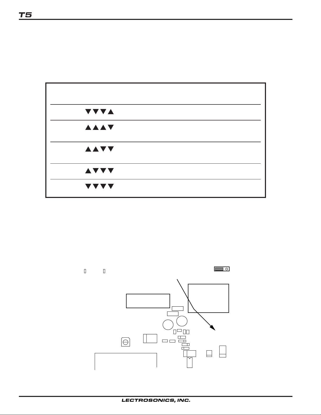
The T5 transmitter is shipped with pin 1 of the XLR input connector tied directly to ground. If a floating input is
desired, a ground lift jumper is provided. This jumper is located inside the unit on the PC board near the rear panel
XLR jack. Place the jumper in the desired position as shown in the figure below.
Gnd Position
Lift Position
XLR
Connector
17239X3
GND
LIFT
BNC
Connector
Ground Lift
Jumper
DIP
Switches
Location of Ground Lift Jumper
8
Page 9

TROUBLESHOOTING
SYMPTOM POSSIBLE CAUSE
IFB Transmitter
DISPLAY NOT LIT OR
BLINKING ON AND OFF
NO TRANSMITTER MODULATION LEDs • AUDIO LEVEL turned all the way down.
NO RECEIVED SIGNAL • Transmitter not turned on.
NO SOUND (OR LOW SOUND LEVEL),
RECEIVER LED IS ON
DISTORTED SOUND
lamps
• External power supply disconnected or inadequate.
• The External DC power input is protected by an auto-reset
polyfuse. Disconnect power and wait about 10 seconds for the
fuse to reset.
• Mic capsule is damaged or malfunctioning.
• Mic cable damaged or mis-wired.
• Receiver antenna missing or improperly positioned. (The headset
cable is the antenna.).
• Transmitter and receiver not on same frequency. Check
on transmitter and receiver.
• Operating range is too great.
• Transmitter antenna not connected.
• Transmitter switch in the TUNE position. Switch to XMIT mode.
• Receiver output level set too low.
• Receiver earphone cable is defective or mis-wired.
• Sound system or transmitter input is turned down.
• Transmitter gain (audio level) is far too high. Check mod level
on transmitter as it is being used. (Refer to Operating
Instructions section for details on gain adjustment.)
• Receiver output may be mismatched with the headset or
earphone. Adjust output level on receiver to the correct level
for the headset or earphone.
• Excessive wind noise or breath “pops.” Reposition microphone
and/or use a larger windscreen.
• Transmitter is not set to same frequency as receiver. Check that
frequency on receiver and transmitter match.
HISS AND NOISE,
AUDIBLE DROPOUTS
• Transmitter gain (audio level) far too low.
• Receiver antenna missing or obstructed. (The headset cable is the
antenna.)
• Transmitter antenna missing or mismatched. Check that the correct
antenna is being used
• Operating range too great.
• Defective antenna or cable.
Rio Rancho, NM – USA
9
Page 10

FREQUENCY BLOCKS AND RANGES
The table below lists the factory designated frequency
ranges available for the T5 IFB Transmitter.
Each T5 transmitter is built to cover a pre-selected range
of frequencies (a “block”) as shown below. The transmitter will tune to any of 256 different frequencies within this
factory assigned block.
The block number is determined by this formula:
25.6 × Freq. (MHz) = Lowest freq. (MHz) in the block
To determine a block number from a frequency:
Freq. (MHz) divided by 25.6 = Block number
It is handy to remember these formulas, in case you do
not have a copy of the table. For example, suppose you
need to know which block covers 685.500 MHz, without
using the table:
685.500 divided by 25.6 = 26.77734375
BLOCK RANGE
21 537.600 - 563.100 Brown 4.74"
22 563.200 - 588.700 Red 4.48"
FREQUENCY
The first two digits left of the decimal are the block
number. In this case, 685.500 MHz falls within block 26.
The T5 IFB transmitter antennas are color coded to
indicate the frequency block that they operate within.
The length of the antenna varies with the frequency
block. The actual length of the antenna is not as critical
as it might appear in the table below. The usable bandwidth of the A6U antennas are +/- 50 MHz from the
center frequency, so it is acceptable to use an antenna
from an adjacent block above or below the operating
frequency is some loss in range can be tolerated.
The color of the antenna sleeve is in keeping with
standard resistor value color codes for the second digit
of the block number.
ANT SLEEVE ANTENNA
COLOR WHIP LENGTH
23 588.800 - 614.300 Orange 4.24”
24 614.400 - 639.900 Yellow 4.01"
25 640.000 - 665.500 Green 3.81"
26 665.600 - 691.100 Blue 3.62"
27 691.200 - 716.700 Violet (Pink) 3.46"
28 716.800 - 742.300 Grey 3.31"
29 742.400 - 767.900 White 3.18"
30 768.000 - 793.500 Orange/Black 3.08"
31 793.600 - 819.100 Orange/Brown 2.99”
32 819.200 - 844.700 Orange/Red 2.92”
33 844.800 - 865.000 Orange/Orange 2.87”
REPLACEMENT PARTS and ACCESSORIES
Part No. Description
10
21586 DC16A Pigtail power cable, LZR to strip & tin
A500 RA B(block #) Antenna, flex
Page 11

IFB Transmitter
SPECIFICATIONS AND FEATURES
Operating Frequencies: 525.0 MHz to 862.0 MHz (See page 10.)
Frequencies (Channels per block): 256
Channel Spacing: 100 kHz Standard (Programmable for 25 kHz spacing.)
Spurious & Harmonic Suppression: 40 dB below carrier at freq. above 1 GHz
Frequency Stability: ±.002% (20 ppm) @ 25° C
Temperature Stability: ±.005% (50 ppm) from -30° C to +50° C
Channel Selection: Momentary pushbutton switches, TUNE Up and Down
Pilot Tone: 29.997 kHz
Modulation: FM, ±20 kHz deviation audio, + 4.5 kHz pilot tone
Audio Response: 100 Hz to 10 kHz, ±1 dB, -3dB (system response)
Audio Compressor: 2 to 1
RF Power Output: 50 mw, nominal
Output Impedance: 50 ohms
Audio Input Levels: +4 dBu, -6 dBu, and -40 dBu, dry inputs, (no phantom power and isolated inputs
Audio Input Config: Balanced and Unbalanced, rear panel selectable
Audio Input Impedance: Greater than 2K balanced, greater than 1K unbalanced
Gain Control Range: 43 dB, Semi-log Rotar y control
Audio Input Jack: Standard XLR female connector
Input Power: 12 to 14 VDC typical, 250 ma. max.; Max. Input Range 11 to 18 VDC
Power Input Jack: Coax type, locking LZR RL26AE
Indicators: LED for -20 dB modulation
Front panel controls: Audio Level rotary knob
Rear panel controls: Mode Select, 4 section DIP switch
Weight: 9 Oz.
Size: 5.25" long (including connectors) x 3.25" wide x 1.25" high
70 dB below carrier at freq. below 1 GHz
for +/-50Vdc max,) rear panel selectable for Line, Mic, RTS 1, RTS 2, and Clear Comm
for Line, Mic. RTS 1, RTS 2, and Clear Comm
at any gain setting
LED for 0 dB modulation
4 Digit 7-segment LED displays for frequency and power on
with adjustable brightness
Power OFF-TUNE-XMIT, 3 position slide switch
TUNE Up momentary pushbutton switch
TUNE down momentary pushbutton switch
Specifications subject to change without notice.
This product meets the CE Compliance Standards - ETS 300 445; January 1996
and I ETS 300 422 (December 1995). A copy of the Declaration of Conformity
may be requested from your dealer or by contacting the factory directly:
Lectrosonics, Inc.
Marketing Department
581 Laser Rd. NE, Rio Rancho, NM 87124 USA
tel: 505-892-4501 fax: 505-892-6243 e-mail: marketing@lectrosonics.com
Rio Rancho, NM – USA
11
Page 12

LIMITED ONE YEAR WARRANTY
LIMITED ONE YEAR WARRANTY
The equipment is warranted for one year from date of purchase against defects in
materials or workmanship provided it was purchased from an authorized dealer. This
warranty does not cover equipment which has been abused or damaged by careless
handling or shipping. This warranty does not apply to used or demonstrator equipment.
Should any defect develop, Lectrosonics, Inc. will, at our option, repair or replace any
defective parts without charge for either parts or labor. If Lectrosonics, Inc. cannot
correct the defect in your equipment, it will be replaced at no charge with a similar new
item. Lectrosonics, Inc. will pay for the cost of returning your equipment to you.
This warranty applies only to items returned to Lectrosonics, Inc. or an authorized
dealer, shipping costs prepaid, within one year from the date of purchase.
This Limited Warranty is governed by the laws of the State of New Mexico. It states the
entire liablility of Lectrosonics Inc. and the entire remedy of the purchaser for any
breach of warranty as outlined above. NEITHER LECTROSONICS, INC. NOR
ANYONE INVOLVED IN THE PRODUCTION OR DELIVERY OF THE EQUIPMENT
SHALL BE LIABLE FOR ANY INDIRECT, SPECIAL, PUNITIVE, CONSEQUENTIAL,
OR INCIDENTAL DAMAGES ARISING OUT OF THE USE OR INABILITY TO USE
THIS EQUIPMENT EVEN IF LECTROSONICS, INC. HAS BEEN ADVISED OF THE
POSSIBILITY OF SUCH DAMAGES. IN NO EVENT SHALL THE LIABILITY OF
LECTROSONICS, INC. EXCEED THE PURCHASE PRICE OF ANY DEFECTIVE
EQUIPMENT.
This warranty gives you specific legal rights. You may have additional legal rights which
vary from state to state.
SERVICE AND REPAIR
If your system malfunctions, you should attempt to correct or isolate the trouble before concluding that the equipment
needs repair. Make sure you have followed the setup procedure and operating instructions. Check out the interconnecting cords and then go through the TROUBLESHOOTING section in the manual
We strongly recommend that you do not try to repair the equipment yourself and do not have the local repair shop
attempt anything other than the simplest repair. If the repair is more complicated than a broken wire or loose connection, send the unit to the factory for repair and service. Don’t attempt to adjust any controls inside the units.
Once set at the factory, the various controls and trimmers do not drift with age or vibration and never require readjustment. There are no adjustments inside that will make a malfunctioning unit start working.
LECTROSONICS, INC.
581 LASER ROAD
RIO RANCHO, NM 87124 USA
December 6, 2001
 Loading...