

Page 1
MBATELIM
HBATELIM
Battery Eliminators
Technical Data
Feature Highlights
• Allows external powering of
Lectrosonics aluminum transmitters
• Standard 9 volt battery contacts and
DC input jack on “dummy battery”
• Modified battery doors available for
both Belt-Pack and Plug-On
transmitters with flip-open style
battery doors
• Modified door preserves use with
regular alkaline or lithium batteries
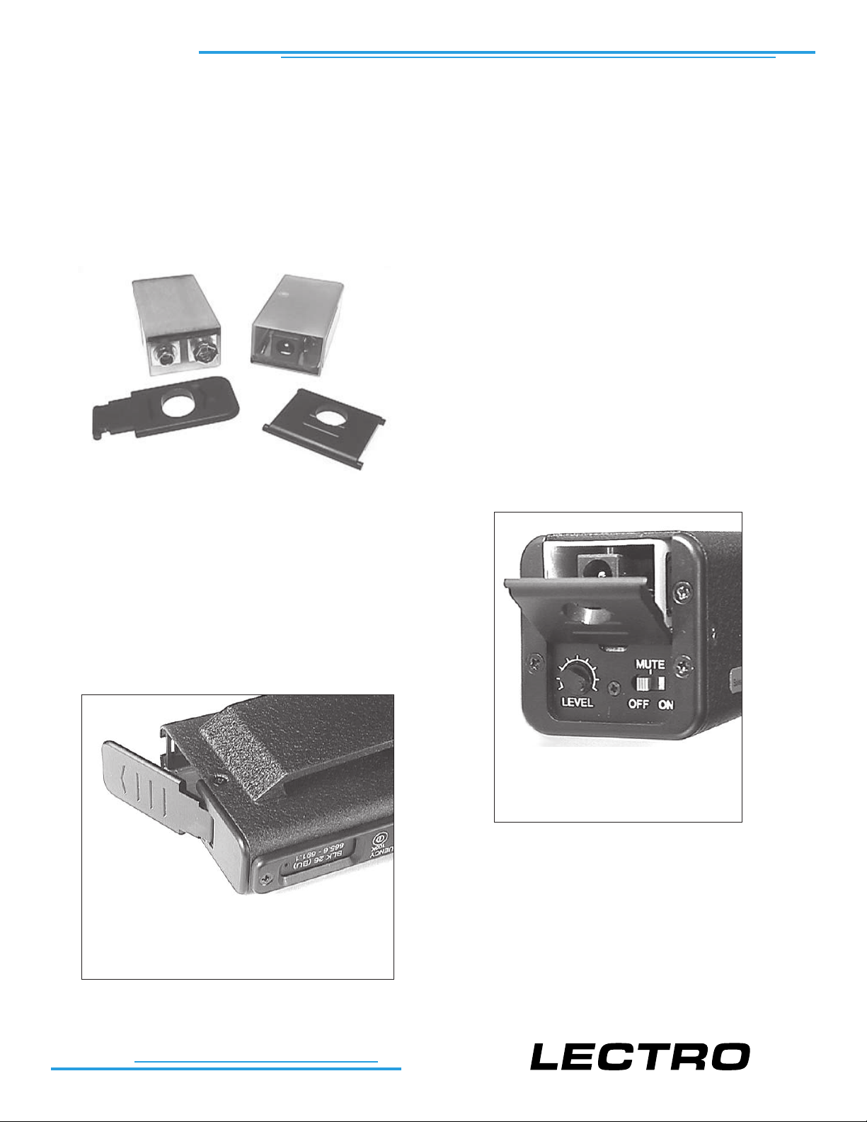
The MBATELIM and HBATELIM battery eliminators provide external powering options for Lectrosonics wireless
transmitters. External DC voltage is fed into the connector at one end of the battery eliminator. The output of the
battery eliminator is regulated 9V DC to power the transmitter at the battery terminals inside the battery
compartment. The modified door allows access to the
power input jack yet still operates with regular alkaline or
lithium batteries. The DC input jack is protected from
reverse polarity.
The MBATELIM model is a kit including the battery
eliminator and a modified battery door that fits any
Lectrosonics aluminum belt-pack transmitter with a
flip-open type door as shown here.
The HBATELIM kit includes a modified
battery door that fits any Lectrosonics
“H” type plug-on transmitters.
The battery eliminator is not recommended for use with
any devices other than the Lectrosonics transmitter types
shown here. Use with any other device will void the factory
warranty. Lectrosonics will not accept resposibility for
damage to nor insure proper operation with any other
devices.
NOT FOR USE WITH TRANSMITTERS THAT HAVE ROTATING TYPE BATTERY DOORS.
T M
Page 2
PLUG-ON
BELT-PACK
TRANSMITTER
INSTRUCTIONS
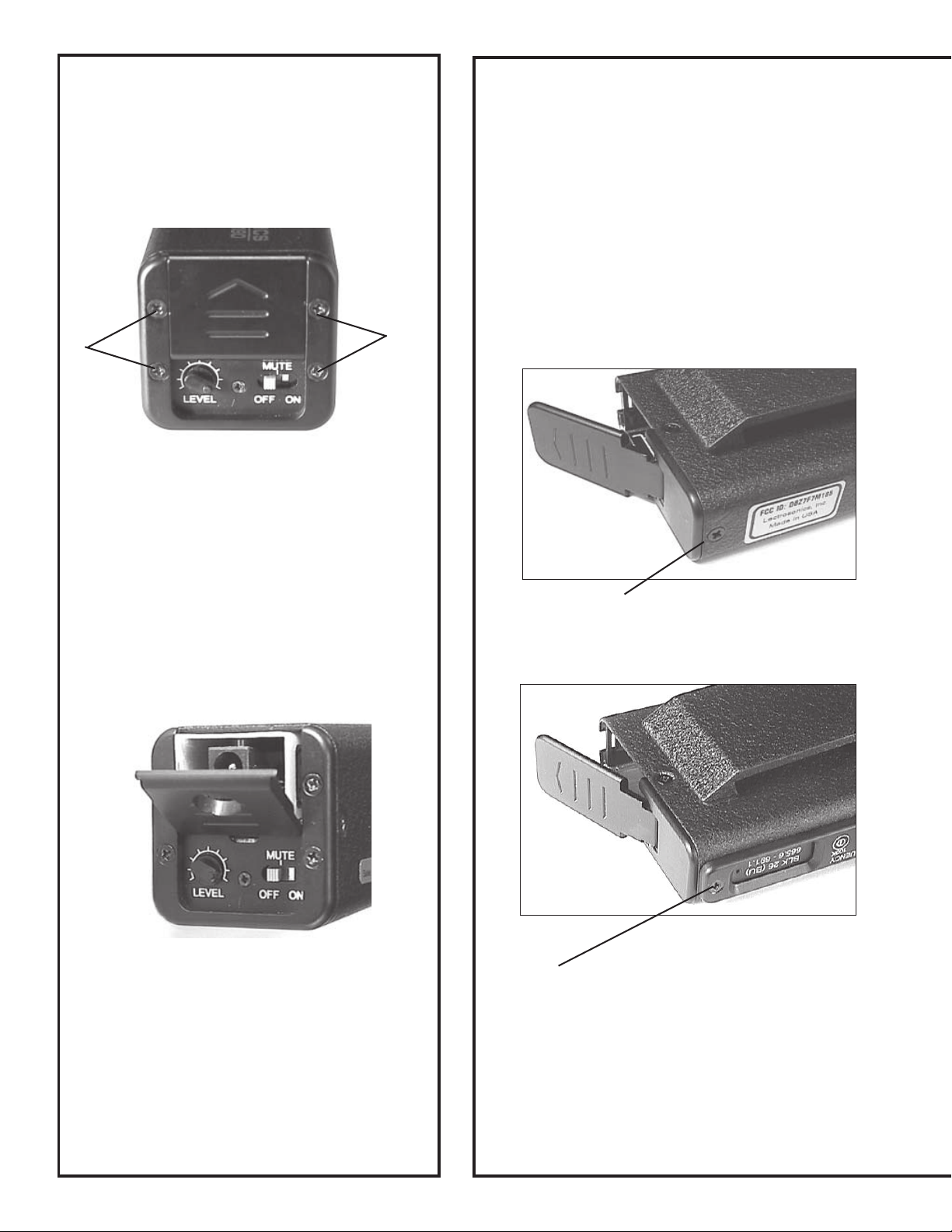
Figure A
Remove the four screws noted in Figure A and
lift bezel from control panel.
Remove battery door and place modified battery
door in exactly the same position. Make sure
modified battery door is oriented the same way
as standard door.
Place the bezel on top of the modified door and
carefully tighten the four screws.
TRANSMITTER
INSTRUCTIONS
Caution:
When removing a standard door to replace
with a modified door, proceed carefully as
the metal spring and tabs can easily be bent
with too much force.
Figure C
Remove rear screw on bottom of case.
Figure B
Insert the HBATELIM. The unit should look like
Figure B.
Fold the door cover down so it is flush with the
bezel and snap into place by pushing toward the
level control.
Figure D
Note: Frequency agile models have sliding door
and bezel on this side, however, screw is in the
same location.
Page 3

Figure E
Open battery door and loosen screw that
holds the spring to the case bottom.
Loosen the screw several turns but do
not remove it.
bezel
metal
tabs
on spring
Figure G
Grip modified door (has hole in it) with thumb and
forefinger and gently slide door hinge into place.
Be careful not to bend the spring or force the
hinge. Make sure the hinge of the modified door
fits behind the two little metal tabs (see inset
above). It will fit into place without much effort.
Re-align all parts before tightening screws.
Tighten screw holding spring to the case bottom
that was loosened in Figure E.
Replace and tighten screw on bottom of case that
was removed in Figure C.
Figure F
Place unit in an upright position while
holding the bezel slightly away from the
casing. Grip door with thumb and forefinger and gently lift it out of the bezel. If the
door does not lift out easily, pry the bezel
up slightly with your fingernail. The door
should now slide out.
Figure H
Install dummy battery as shown so that the connector aligns with the access hole in the door.
Polarity is different on different models—connector will align with access hole in either orientation.
Page 4

9 volt contacts
for battery
eliminator
modified door for
MBATELIM Belt-Pack
transmitters
A closer look
12 volt input jack
for battery
eliminator
center pin (+)
modified door for
HBATELIM Plug-
On transmitters
Specifications
Input: ¨ Minimum-11V DC
Output: 9V DC regulated
Height: 0.662 inches
Width: 1.781 inches
Depth: 0.970 inches
Weight: 14.8 grams
¨ Nominal-12V DC
¨ Max-24V DC with most Lectro
transmitters
¨ Max14V DC with UM250B high
power transmitter (see formula below)
*Formula for figuring voltage for the 12 volt adaptor interface
if 12V is not available. Note: Max of 14V for UM250B; all
others—24V max
(Vin - 9V) X Current = wattage
(wattage must be less than 1 watt)
EXAMPLE:
14. 4 volt supply and a transmitter drain of 100 mA (0.1A)
then:
(14.4V-9V) X 0.1A = 0.54 watt
Since this is less than 1 watt, this is OK.
BATELIM-0701
581 Laser Road NE - Rio Rancho, NM - 87124 USA
tel (505) 892-4501 or (800) 821-1121 - fax (505) 892-6243
Web: www.lectrosonics.com - E-mail: sales@lectrosonics.com
 Loading...