

Page 1

H185
PLUG-ON TRANSMITTER
OPERATING INSTRUCTIONS
and trouble-shooting guide
LECTROSONICS, INC.
Rio Rancho, NM
Page 2

INTRODUCTION
Thank you for selecting the Lectrosonics Professional Series wireless microphone system.
This system represents well over 10 years of manufacturing experience in wireless microphones, and
almost 70 years of design experience. It is the best value available today. You will find that the H185
radiates more power than other standard handheld wireless microphones. This provides both greater
operational range, as well as improved signal-to-noise ratio. In addition, the frequency response of the
H185 is flat to 18kHz. This guarantees that the performance of any microphone you choose will not be
degraded by the H185.
If you are new to wireless microphones, you will discover a new freedom of movement and
convenience. If you are an experienced wireless user, you will be pleasantly surprised with the
effortless, quiet performance of the Lectrosonics Professional Series design. Over time, you will
appreciate the rugged dependability of the H185. Superior mechanical design and construction mean
years of trouble-free use.
Only the H185 transmitter is covered in this manual. A matched transmitter/receiver combination
makes up a "system." Receivers are explained in separate manuals.
The H185 transmitter is constructed of metal and operates on interference-free high band frequencies
from 150MHz to 216MHz. Since the H185 uses the actual microphone case as an antenna, there is no
need for any unsightly extra wires. The H185 plugs into the XLR jack of any hand-held microphone,
giving the user the greatest choice of mics.
The H185 transmitter is FCC type accepted under Part 90 (150-172 MHz), and Part 74 (174-216 MHz)
TABLE OF CONTENTS
INTRODUCTION .......................................... 1
GENERAL TECHNICAL DESCRIPTION .......................... 2
CONTROLS AND FUNCTIONS ................................ 3
OPERATING INSTRUCTIONS ................................. 5
BATTERY REPLACEMENT ................................... 6
TROUBLESHOOTING ....................................... 7
SPECIFICATIONS AND FEATURES ............................ 8
SERVICE AND REPAIR ..................................... 9
RETURNING UNITS FOR REPAIR ............................. 9
WARRANTY ........................................ Back cover
1
Page 3
GENERAL TECHNICAL DESCRIPTION
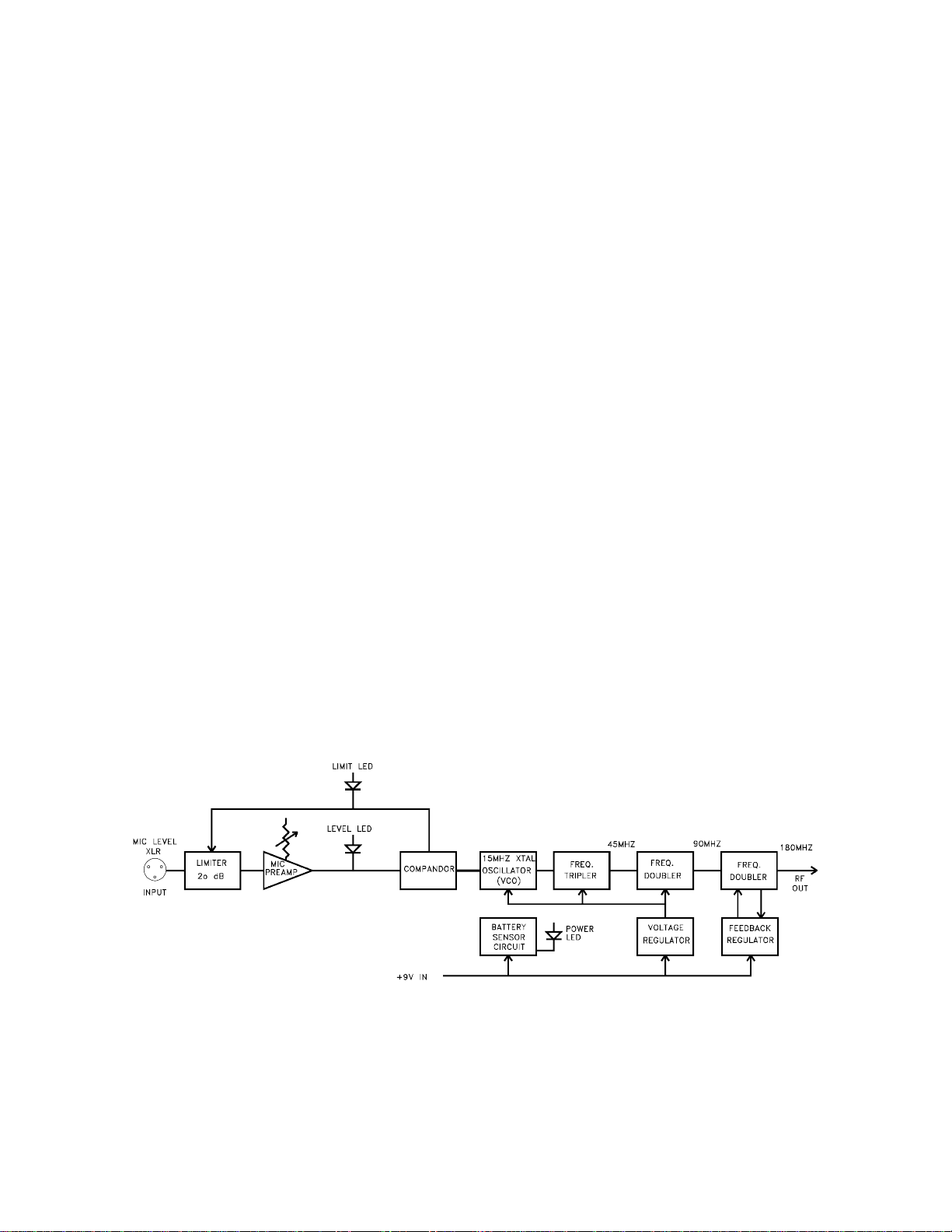
The H185 transmitter is comprised of four major functional subsystems: the input compressor, the mic
preamp/gain control, the compandor, and the RF transmitter (see block diagram below).
The input compressor is a low distortion shunt FET compressor situated before the mic preamp.
Control signals for the compressor are derived after the mic preamp to eliminate any possibility of
overload under any signal condition up to a maximum of 3 Volts input. The range of limiting action
before gross distortion occurs is 20dB.
The mic preamp is an ultra-low noise NE5534 type op-amp. Aside from gain control, this stage also
adds high frequency pre-emphasis to the audio signal. This insures highest signal-to-noise ratios under
varying signal conditions. Gain control is semi-logarithmic to provide smooth gain control action.
The compandor is a high quality audio device that processes the input signal such that large dynamic
ranges of input signal can be transmitted to the receiver without overload or noise. A complementary
system in the receiver recovers the original dynamics of the signal for full audio quality. Compression
and expansion ratios are complementary at 2:1. High frequency pre-emphasis is implemented in the
transmitter to provide another 10dB signal-to-noise ratio improvement. Matching de-emphasis is
provided in all receivers.
The RF transmitter is composed of the crystal stabilized main oscillator followed by a frequency tripler
and two frequency doublers. All three stages are double tuned. Double tuning provides maximum
attenuation of spurious signals, which in turn minimizes the possibility that a transmitter would interfere
with another transmitter/receiver system on another frequency.
All RF stages are biased from a regulated internal source. The output stage has a separate feedback
regulator which not only stabilizes its operating point, but also minimizes AM distortion. These
regulators keep the RF performance consistent from the beginning (9 Volts) to the end (6.5 Volts) of
battery life.
Schematics and alignment instructions will be provided to qualified repair personnel on request.
Figure 1 - H185 Block Diagram
2
Page 4
CONTROLS AND FUNCTIONS
The H185 may be used with a wide variety of microphones. The 3-pin XLR type connector on the
H185 allows the transmitter to be used with any dynamic microphone, as well as many two wire
positive bias lavalier systems (such as those systems supplied by Lectrosonics).
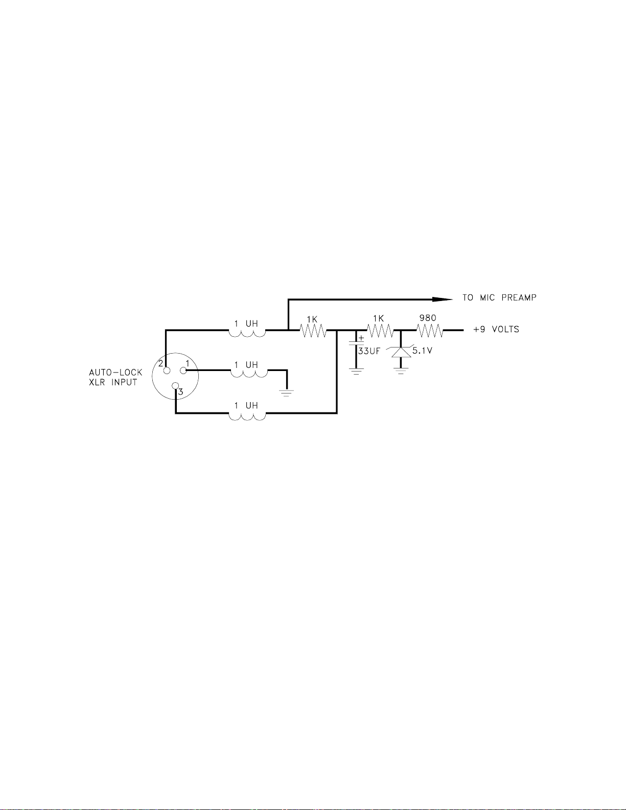
INPUT JACK
Standard 3-pin Switchcraft XLR type. Pin 2 is signal, pin 3 is signal ground, and pin 1 is case ground
(see schematic below). The H185 is self-locking onto a standard microphone. The XLR connector is
permanently bonded to the metal collar, and is not normally replaceable. The electret bias is 5 Volts at
1mA or less. The bias is connected in a "phantom" manner and will not interfere with any standard
balanced microphone. If severe noise is experienced when the microphone is moved with respect to
the H185, the cause is an unbalanced condition between pins 2 and 3 of the microphone.
Figure 2 - Input Jack Schematic
POWER/MUTE SWITCH
Turns the battery power on and off. The center position is an "audio mute" which should be used when
setting the MIC LEVEL control. The "mute" position disconnects the audio signal from the transmitter
and allows you to adjust the audio modulation level without the possibility of feedback. When turning
the transmitter on, pause for a moment in the "mute" position. This will prevent a turn-on surge from
occurring (a "thump" sound).
POWER ON/OFF LED
Glows brightly when battery is good. A weak or dim LED means that the battery is weak, and has
about an hour of operation left. If the LED fails to light, the battery should be replaced. The power
LED should light up in both the "mute" and "on" positions of the POWER/MUTE SWITCH.
3
Page 5

The POWER LED is connected to a precision battery test circuit that continuously monitors battery
voltage. The LED is at full brightness with a new 9 Volt alkaline or lithium battery. As the battery
voltage drops during use, the LED brightness will also decrease. After 12 to 15 hours (25 to 30 hours
with a lithium battery) the battery voltage will be about 7 Volts. The LED will be completely
extinguished. Since the internal circuits are all tightly regulated and the RF output stage has a
separate discrete regulator, the transmitter will continue to operate to a battery voltage of 6.5 Volts.
From 6.5 Volts to 6 Volts, the transmitter will still operate, but with degraded performance. Please note
that a weak battery will sometimes light the POWER LED immediately after turn on, but soon will
discharge to the point where the LED will extinguish.
The combination of an accurate battery condition indicator and regulation of all internal circuits
guarantees much longer battery life, as well as consistent performance versus battery life.
MODULATION LEDS: Indicate the proper setting of the MIC LEVEL control.
LEVEL LED: Flickers or glows all the time if the audio volume is adequate for normal operation.
LIMIT LED: Lights up when the audio volume is high, indicating that the signal level is being limited by
the compressor. Optimum signal-to-noise ratio is obtained when the limit LED lights occasionally.
MIC LEVEL: Used to adjust the audio input volume for the proper modulation level. Rotate knob until
the LEVEL LED flickers when there is an input signal. The LIMIT LED should light occasionally.
Figure 3 - Top View and Control Panel
4
Page 6

OPERATING INSTRUCTIONS
1) Insert the H185 into the selected microphone. Listen for the "click" that indicates the H185 has
locked on to the microphone. Pull on the mic to insure proper locking has occurred.
Figure 4 - Attaching the Microphone
2) Turn the power switch to the "MUTE" position on both the transmitter and the receiver. The "MUTE"
position allows internal voltages to stabilize before audio signal paths are opened.
3) Hold the microphone as you will when you will be using it.
4) Speak as loudly as you expect to speak in normal system use. Rotate the MIC LEVEL knob so that
the LEVEL LED flickers or stays lit as you speak. The LIMIT LED should light up on loud "peaks."
Occasional lighting of the LIMIT LED (about 10-15% of the time) indicates proper operation and optimum
signal-to-noise ratio. Even when the transmitter is limiting, little distortion is produced because of the
high linearity of the gain control circuit in the H185.
5) Move switches to "ON" position on both the transmitter and the receiver and adjust the volume of the
sound system.
NOTE:
The MIC LEVEL control should not be used to control the volume of your sound system. This is
accomplished using the level control on the receiver, or a level control on the mixing console.
If the mic level is too high -- the LIMIT LED will light frequently or stay on. This condition may cause
distortion.
If the mic level is too low -- neither LED will light, or the LEVEL LED will light dimly. This condition will
cause hiss and noise. You may experience severe reduction in apparent range if the modulation level
is too low. It may sound as if you are getting dropouts. What is actually happening is that you are
hitting your noise floor because the S/N ratio has been compromised by the low modulation.
5
Page 7

The LEVEL LED turns on at -10dB below full deviation. The LIMIT LED turns on at full deviation and
indicates that the input shunt compressor is operating. The input compressor operates over a full 20dB
range regardless of the gain control setting. The compressor uses a true absolute value circuit to
detect both positive and negative peaks. The attack time is 2 milliseconds and the release time is 80
milliseconds. Occasional limiting is desirable, indicating that the gain is correctly set and the transmitter
is fully modulated.
BATTERY REPLACEMENT
The H185 transmitter is powered by a standard alkaline 9 Volt battery. A lithium 9 Volt battery may
also be used. It is important that you use ONLY an ALKALINE or LITHIUM battery for longest life.
Standard zinc-carbon batteries marked "heavy duty" or "long-lasting" are not adequate. They will
provide only about 4 hours of operation. Similarly, nicad rechargeable batteries only give 4 hours of
operation, and will also run down quite abruptly. Alkaline batteries provide about 15 hours of operation,
while lithium batteries will give almost 30 hours of useful life.
To open the battery compartment, press outward on the cover door in the direction of the arrow as
shown in the drawing. Only slight, sliding pressure is needed to open and close the battery door.
Figure 5 - Battery Compartment Action
Swing the door open and take note of the polarity marked inside showing the location of the positive (+)
and negative (-) terminals. Insert the battery and close the cover by pressing in and across, reversing
the opening procedure outlined above. Note that the battery door will NOT close if the battery is
inserted incorrectly, since the terminals will hit a protective polarity barrier.
6
Page 8

TROUBLESHOOTING
Before going through the following chart, be sure that you have a good battery in the transmitter the
red power LED on the transmitter panel should glow brightly.
SYMPTOM POSSIBLE CAUSE
NO AUDIO IS HEARD BUT RECEIVER 1) On/Off switch is in "mute"position
RF LED IS ON receiver or transmitter.
2) Microphone on/off switch is in "off" position.
NOTE: If the modulation level 3) Volume is turned down or off on
LEDs on the receiver are transmitter or receiver.
indicating properly, the problem 4) Receiver not properly connected to
is NOT in the transmitter. other audio equipment.
5) Transmitter POWER switch may be turned
on and off (i.e. through the mute position). A
"thump" should be heard in the sound, again
indicating a properly functioning receiver.
NO SOUND IS HEARD AND RECEIVER 1) Transmitter not turned on. Check
RF LED IS OFF for power LED.
2) Receiver antenna may be defective or
disconnected.
3) Transmitter and receiver frequencies don’t
match. Check frequency labels.
NOISE (HISS) IS HEARD ALONG 1) MIC LEVEL is too low (see page 5).
WITH THE SIGNAL 2) Transmitter and receiver may be too far from
one another.
3) Receiver antenna may be defective or
disconnected.
DISTORTED SOUND 1) MIC LEVEL is too high (see page 5).
2) Mic may be distorting; try a different mic and
listen again.
3) PA system may be overloading.
EXCESSIVE FEEDBACK 1) MIC LEVEL may be set too high
(see page 5).
2) Sound system volume set too high.
3) Microphone too far from the user’s mouth.
4) Loudspeakers may be too close to the mic.
7
Page 9

SPECIFICATIONS AND FEATURES
Operating frequencies: 150 to 216 MHz
RF Power output: 50mW
Deviation: +/- 15kHz
Spurious radiation: 55dB below carrier
Equivalent input noise: -126dBV
Input level: Nominal 2mV to 300mV
(before compression)
Input impedance: 22k Ohms (compatible with all Lo-Z
microphones)
Input compressor: Soft compressor, 20 dB range allows 3 Volt
max. input
Gain control range: 43dB; semi-log rotary control
Modulation indicators: Dual LEDs indicate modulation level and onset
of limiting
Controls: 3 position "OFF-MUTE-ON" for noiseless
operation; rotary knob adjusts audio gain
Connector: 3-pin XLR type with auto-locking collar
Battery: Any 9 Volt alkaline or lithium battery.
Weight: 7 ozs. including battery
Dimensions: 1.5 x 1.5 x 4.2 inches
Emission Designator: 54KOF3E
8
Page 10

SERVICE AND REPAIR
If your system malfunctions, you should attempt to correct or isolate the trouble before concluding that
the equipment needs repair. Make sure you have followed the setup procedure and operating
instructions. Check out the inter-connecting cords and then go through the TROUBLE SHOOTING
section in the manual
We strongly recommend that you do not try to repair the equipment yourself and do not have the local
repair shop attempt anything other than the simplest repair. If the repair is more complicated than a
broken wire or loose connection, send the unit to the factory for repair and service. Don’t attempt to
adjust any controls inside the units. Once set at the factory, the various controls and trimmers do not
drift with age or vibration and never require readjustment. There are no adjustments inside that will
make a malfunctioning unit start working.
LECTROSONICS service department is equipped and staffed to quickly repair your equipment.
In-warranty repairs are made at no charge in accordance with the terms of the warranty. Out of
warranty repairs are charged at a modest flat rate plus parts and shipping. Since it takes almost as
much time and effort to determine what is wrong as it does to make the repair, there is a charge for an
exact quotation. We will be happy to quote approximate charges by phone for out of warranty repairs.
RETURNING UNITS FOR REPAIR
You will save yourself time and trouble if you will follow the steps below:
A. DO NOT return equipment to the factory for repair without first contacting us by letter or by phone.
We need to know the nature of the problem, the model number and the serial number of the
equipment. We also need a phone number where you can be reached 8 am to 4 pm (Mountain
Standard Time).
B. After receiving your request, we will issue you a return authorization number (R.A.). This number
will help speed your repair through our receiving and repair departments. The return authorization
number must be clearly shown on the outside of the shipping container.
C. Pack the equipment carefully and ship to us, shipping costs prepaid. If necessary, we can provide
you with the proper packing materials. UPS is usually the best way to ship the units. Heavy units
should be "double-boxed" for safe transport.
D. We also strongly recommend that you insure the equipment, since we cannot be responsible for
loss of or damage to equipment that you ship. Of course, we insure the equipment when we ship
it back to you.
Mailing address: Shipping address:
Lectrosonics, Inc. Lectrosonics, Inc.
PO Box 15900 581 Laser Rd.
Rio Rancho, NM 87174 Rio Rancho, NM 87124
USA USA
Telephones:
Regular: (505) 892-4501
WATS: (800) 821-1121
FAX: (505) 892-6243
9
Page 11

LIMITED ONE YEAR WARRANTY
The equipment is warranted for one year from date of purchase against
defects in materials or workmanship provided it was purchased from an
authorized dealer. This warranty does not cover equipment which has
been abused or damaged by careless handling or shipping. This
warranty does not apply to used or demonstrator equipment.
Should any defect develop, we will, at our option, repair or replace any
defective parts without charge for either parts or labor. If we cannot
correct the defect in your equipment, we will replace it at no charge
with a similar new item. We will pay for the cost of returning your
merchandise to you.
This warranty applies only to items returned to us, shipping costs
prepaid, within one year from the date of purchase.
This warranty gives you specific legal rights. You may have additional
legal rights which vary from state to state.
LECTROSONICS, INC.
581 LASER ROAD
RIO RANCHO, NM 87124 USA December 16, 1994
 Loading...