

Page 1

H175DC
Plug-On Transmitter
OPERATING INSTRUCTIONS
and trouble-shooting guide
Digital Code Squelch
LECTROSONICS, INC.
Rio Rancho, NM
Page 2

This page intentionally blank.
2
Page 3

Plug-On Transmitter
INTRODUCTION
Thank you for selecting the Lectrosonics Professional Series wireless microphone
system.
This system represents well over 20 years of manufacturing experience in wireless
microphones, and almost 70 years of design experience. It is the best value available today. You will find that the H175DC radiates more power than other standard
handheld wireless microphones. This provides both greater operational range, as
well as improved signal-to-noise ratio.
If you are new to wireless microphones, you will discover a new freedom of movement and convenience. If you are an experienced wireless user, you will be pleasantly surprised with the effortless, quiet performance of the Lectrosonics Professional
Series design. Over time, you will appreciate the rugged dependability of the
H175DC. Superior mechanical design and construction mean years of trouble-free
use.
Only the H175DC transmitter is covered in this manual. A matched transmitter/
receiver combination makes up a “system.” Receivers are explained in separate
manuals.
The H175DC transmitter is constructed of metal and operates on interference-free
high band frequencies from 169 to 172MHz and 174 to 186MHz. Since the H175DC
uses the actual microphone case as an antenna, there is no need for any unsightly
extra wires. The H175DC plugs into the XLR jack of any hand-held microphone,
giving the user the greatest choice of mics.
TABLE OF CONTENTS
INTRODUCTION .................................................................................................. 3
GENERAL DESCRIPTION .................................................................................. 4
CONTROLS AND FUNCTIONS .......................................................................... 5
OPERATING INSTRUCTIONS ............................................................................ 6
BATTERY REPLACEMENT ................................................................................. 8
TROUBLESHOOTING ......................................................................................... 9
SPECIFICATIONS AND FEATURES ................................................................. 10
SERVICE AND REPAIR ..................................................................................... 11
RETURNING UNITS FOR REPAIR ................................................................... 11
WARRANTY ......................................................................................... Back cover
H175DC series transmitters are FCC type accepted under the following Parts:
Part 90 (150-172 MHz)
Part 74 (174-216 MHz)
Rio Rancho, NM – USA
3
Page 4
GENERAL DESCRIPTION
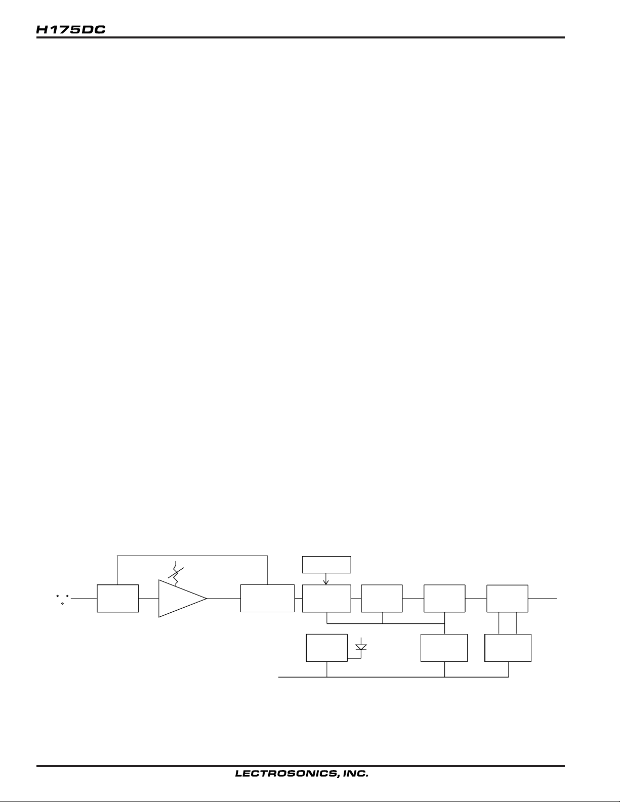
The H175DC is a “plug-on” transmitter that converts any microphone with an XLR connector to wireless operation.
The transmitter is comprised of four major functional subsystems: the mic preamp/gain control, the compandor, the
compressor/limiter and the RF transmitter (see block diagram below).
The digital code system provides much more reliable control over the receiver audio output than a conventional
squelch can provide. The transmitter generates a 9-bit code at turn on, and another code at turn off, to open and
close the audio output on the receiver. The squelch on the receiver cannot be opened by anything other than the
specific code it is programmed to receive. This superior squelch system is very necessary when the receiver is
connected into an automatic mixing system.
The input jack provides a phantom 5 Volts DC positive bias for all Lectrosonics’ electret lavalier microphones. Many
other electret microphones may be adapted to the H175DC Series by making wiring changes in the microphone
connector.
The mic preamp is an ultra-low noise type op-amp. Aside from gain control, this stage also adds high frequency preemphasis to the audio signal. This insures highest signal-to-noise ratios under varying signal conditions. Gain
control is semi-logarithmic to provide smooth gain control action.
The compandor is a high quality audio device that processes the input signal such that large dynamic ranges of input
signal can be transmitted to the receiver without overload or noise. A complementary system in the receiver recovers
the original dynamics of the signal for full audio quality. Compression and expansion ratios are complementary at 2:1.
High frequency pre-emphasis is implemented in the transmitter to provide another 10dB signal-to-noise ratio improvement. Matching de-emphasis is provided in all receivers.
The compressor/limiter is a low distortion shunt FET compressor. Control signals for the compressor are derived
after the compandor to eliminate any possibility of overload under any signal condition up to a maximum of 3 Volts
input. The range of limiting action before gross distortion occurs is 35dB.
The RF transmitter is composed of the crystal stabilized main oscillator followed by a frequency tripler and two
frequency doublers. All three stages are double tuned. Double tuning provides high attenuation of spurious signals,
which in turn minimizes the possibility that a transmitter would interfere with another transmitter/receiver system on
another frequency.
All RF stages are biased from a regulated internal source. The output stage has a separate feedback regulator which
not only stabilizes its operating point, but also minimizes AM distortion. These regulators keep the RF performance
consistent from the beginning (9 Volts) to the end (6.5 Volts) of battery life.
D.C.S.
MIC LEVEL
XLR
INPUT
LIMITER
35 dB
MIC
PREAMP
COMPANDOR
15MHZ XTAL
OSCILLATOR
(VCO)
BATTERY
SENSOR
CIRCUIT
FREQ.
TRIPLER
POWER
LED
45MHZ
FREQ.
DOUBLER
VOLTAGE
REGULATOR
90MHZ
FREQ.
DOUBLER
FEEDBACK
REGULATOR
180MHZ
RF
OUT
+9V IN
4
Page 5

Plug-On Transmitter
CONTROLS AND FUNCTIONS
The H175DC may be used with a wide variety of microphones. The 3-pin XLR type connector on the H175DC allows
the transmitter to be used with any dynamic microphone, as well as many two wire positive bias lavalier systems
(such as those systems supplied by Lectrosonics.)
INPUT JACK
Standard 3-pin XLR type. Pin 2 is signal, pin
3 is signal ground, and pin 1 is case ground
(see schematic in Figure 2.) The H175DC
locks onto a standard microphone. The XLR
connector is permanently bonded to the to
the locking assembly, and is not normally
replaceable. The electret bias is 5 Volts at
1mA or less. The bias is connected in a
AUTO-LOCK
XLR INPUT
+
33UF
1K
5.1V
1 UH
12
3
1 UH
1 UH
1K
TO MIC PREAMP
980
+9 VOLTS
“phantom” manner and will not interfere with
any standard balanced microphone. If severe noise is experienced when the microphone is moved with respect to
the H175, the cause is an unbalanced condition between pins 2 and 3 of the microphone.
POWER OFF/ON
Turns the battery power on and off.
BATTERY POWER LED
Glows brightly when battery is good. A weak or dim power LED means that the battery is weak, and has about an
hour of operation left. If the LED fails to light, the battery should be replaced. The POWER LED is connected to a
precision battery test circuit that continuously monitors battery voltage. The LED is at full brightness with a new 9 Volt
alkaline. As the battery voltage drops during use, the LED brightness will also decrease. After 12 to 15 hours the
battery voltage will be about 7 Volts. The LED will be completely extinguished. Since the internal circuits are all
tightly regulated and the RF output stage has a separate discrete regulator, the transmitter will continue to operate to
a battery voltage of 6.5 Volts. From 6.5 Volts to 6 Volts, the transmitter will still operate, but with degraded performance. Please note that a weak battery will sometimes light the POWER LED immediately after turn on, but soon
will discharge to the point where the LED will extinguish.
The combination of an accurate battery condition indicator and regulation of all internal circuits guarantees much
longer battery life, as well as consistent performance versus battery life.
LEVEL CONTROL
Used to adjust the audio input volume for the proper modulation level. Rotate knob until the LEVEL LED on the
receiver flickers when there is an input signal. The LIMIT LED on the receiver should light occasionally.
BATTERY
POWER
2
3
1
TOP VIEW
LED
ON
LEVEL
OFF
CONTROL PANEL
(Note: The H175DC, Digital Code Squelch version is operationally identical to the standard H175.)
Rio Rancho, NM – USA
5
Page 6

OPERATING INSTRUCTIONS
1) Install the Microphone onto the transmitter.
a. Unscrew the collar by turning it fully clockwise until it
stops.
b. Turn the collar two turns counter-clockwise to
extend the locking tab
c. Press the mic onto the XLR connector until you
hear a “click.” The click indicates the mic has
locked into place.
Locking tab fully retracted
Knurled knob
turned completely
clockwise.
Compression Washer
Locking tab partially extended
Knurled knob
turned two turns
counter-clockwise.
Click!
d. Tighten the collar by turning it counter-clockwise.
e. Pull on the mic to ensure locking.
f. For added security, tighten the setscrew.
Warning: Worn mics may not “click” and may not properly lock.
Be sure to use the setscrew to lock it in place.
6
Page 7

Plug-On Transmitter
2) Turn on the receiver and adjust the output level to minimum.
3) Turn on the transmitter. The CODE LED on the receiver should come on.
4) Hold the microphone as you will when you will be using it.
5) Speak as loudly as you expect to speak in normal system use. Adjust the MIC LEVEL on the transmitter so that
the LEVEL LED on the receiver flickers or stays lit as you speak. The LIMIT LED on the receiver should light up
on loud “peaks.” (The Level LED may be labeled as “-20” and the Limit LED may be labeled as “0dB.”)
Occasional lighting of the LIMIT LED (about 10-15% of the time) indicates proper operation
and optimum signal-to-noise ratio.
Even when the transmitter is limiting, little distortion is produced because of the high linearity of the gain control
circuit in the H175.
6) Adjust the receiver output level as necessary.
It is possible for the system to appear to be “locked-up” and not working. This can happen if the transmitter is
turned on while out of range of the receiver or if the transmitter is turned on before the receiver. If this happens,
the receiver never gets the code that tells it to “turn on.” The cure is simple. Move the transmitter into range of the
receiver and turn it off then back on. You can always tell if the receiver is enabled by looking at the CODE LED. If
the LED is on, the receiver is enabled and ready for use.
NOTE:
The LEVEL control on the transmitter should not be used to control the volume of your sound system. This should be
done using the level control on the receiver, or a level control on the mixing console.
If the mic level is too high - the LIMIT LED on the receiver will light frequently or stay on. This condition may cause
distortion.
If the mic level is too low — neither LED will light, or the LEVEL LED (on the receiver) will light dimly. This condition
will cause hiss and noise. You may experience severe reduction in apparent range if the modulation level is too low. It
may sound as if you are getting dropouts. What is actually happening is that you are hitting your noise floor because
the S/N ratio has been reduced by the low modulation.
The input compressor operates over a full 30dB range regardless of the gain control setting. The compressor uses a
true absolute value circuit to detect both positive and negative peaks. The attack time is 2 milliseconds and the
release time is 80 milliseconds. Occasional limiting is desirable, indicating that the gain is correctly set and the
transmitter is fully modulated.
SETUP FOR OLDER RECEIVERS
This transmitter features the new Wide Range Limiting circuitry to prevent input overload during loud peaks. When
used with receivers that have not been adjusted for this limiter, the Modulation LEDs on the receiver control panel may
not function as indicated above. Audio peaks are indicated by an LED labeled “0dB” or “LIMIT” on the receiver (red
LED on the Long Ranger). If this LED on your receiver will not light even with loud audio peaks and the transmitter
gain set at maximum, use the instruction in the following paragraph to adjust the transmitter input gain.
Follow the procedure described in step 5 above except adjust the gain control so that the
“LEVEL” or “-20” LED on the receiver (green LED on the Long Ranger) lights up about 50%
of the time while you are speaking.
The net result of this adjustment will produce essentially the same results as the setup procedure described in the
manual. There is no loss of performance in the wireless system using this procedure.
Receivers can be adjusted at the factory to work with the new Wide Range Limiting circuitry. The adjustment to the
receiver is simply to set the “LIMIT” or “0dB” LED threshold slightly lower so that it will indicate peaks in the audio.
There is no difference in the audio quality whether or not the receiver LEDs are adjusted for the new limiting circuitry.
If you have questions, or would like to arrange for the factory to adjust your receiver, call (800) 821-1121 and ask for
the service department.
Rio Rancho, NM – USA
7
Page 8

BATTERY REPLACEMENT
The H175DC transmitter is powered by a standard alkaline 9 Volt battery. It is important that you use ONLY an ALKALINE battery for longest life. Standard zinc-carbon batteries marked “heavy duty” or “long-lasting” are not adequate.
They will provide only about 4 hours of operation. Similarly, nicad rechargeable batteries only give 4 hours of operation, and will also run down quite abruptly. Alkaline batteries provide about 12 to 14 hours of operation.
RELEASE
DOOR
SWING OPEN
OBSERVE
POLARITY
To open the battery compartment, press outward on the cover door in the direction of the arrow as shown in the
drawing. Only slight, sliding pressure is needed to open and close the battery door.
Swing the door open and take note of the polarity marked inside showing the location of the positive (+) and negative () terminals. Insert the battery and close the cover by pressing in and across, reversing the opening procedure outlined
above. Note that the battery door will NOT close if the battery is inserted incorrectly, since the terminals will hit a
protective polarity barrier.
8
Page 9

Plug-On Transmitter
TROUBLESHOOTING
Before going through the following chart, be sure that you have a good battery in the transmitter. It is important that
you follow these steps in the sequence listed.
SYMPTOM POSSIBLE CAUSE
TRANSMITTER BATTERY LED OFF 1) Unit turned off. Check front panel on/off slide switch.
2) Battery is inserted backwards.
3) Battery is dead.
RECEIVER RF OR CODE LAMP OFF 1) Transmitter not turned on.
2) Transmitter battery is dead.
3) Receiver antenna missing or improperly positioned.
4) Transmitter and receiver not on same frequency or
transmitter and receiver codes are different. Check labels
on transmitter and receiver.
5) Operating range is too great.
NO SOUND BUT RECEIVER MOD LEVEL LEDs ARE ON
1) Receiver audio is muted. Refer to receiver manual.
2) Receiver audio output is disconnected or cable is
defective or mis-wired.
3) Sound system or recorder input is turned down.
DISTORTED SOUND 1) Transmitter gain (audio level) is too high. Speak or sing
into the transmitter and check mod level lamps on the
receiver (see Operating Instructions.)
2) Receiver output may be mis-matched with the sound
system or recorder input.
3) Excessive wind noise or breath “pops.”
HISS AND NOISE -- AUDIBLE DROPOUTS 1) Transmitter gain (audio level) too low.
2) Receiver antenna missing or obstructed.
3) Operating range too great.
EXCESSIVE FEEDBACK 1) Transmitter gain (audio level) much too high causing the
limiter to reduce the gain-before-feedback. Check gain
adjustment and/or reduce receiver output level
(See Operating Instructions.)
2) Transmitter/Mic too close to speaker system.
3) Move transmitter closer to the user’s mouth and reduce
the level of the sound system.
Rio Rancho, NM – USA
9
Page 10

SPECIFICATIONS AND FEATURES
Operating frequencies: 169 to 172 MHz; 174 to 186 MHz
RF Power output: 50mW
Deviation: ±15kHz
Spurious radiation: 55dB below carrier
Equivalent input noise: -121dBV
Input
Types: 200 Ohm dynamic
5V phantom power
1k Ohm, 2-wire electret with 5 VDC positive bias
Level: Nominal 2mV to 300mV (before compression)
Impedance: 22k Ohms (compatible with all Lo-Z microphones)
Input compressor: Soft compressor, 30 dB range allows 3 Volt max. input
Gain control range: 43dB; semi-log rotary control
Controls: 2 position Power switch; Rotary knob adjusts audio gain
Connector: 3-pin XLR type with locking collar
Battery: Any 9 Volt alkaline battery
Weight: 7 ozs. including battery
Dimensions: 1.5 x 1.5 x 4.2 inches
Emission designator: 40K0F3E
Specifications subject to change without notice
10
Page 11

Plug-On Transmitter
SERVICE AND REPAIR
If your system malfunctions, you should attempt to correct or isolate the trouble before concluding that the equipment
needs repair. Make sure you have followed the setup procedure and operating instructions. Check out the interconnecting cords and then go through the TROUBLE SHOOTING section in the manual
We strongly recommend that you do not try to repair the equipment yourself and do not have the local repair shop
attempt anything other than the simplest repair. If the repair is more complicated than a broken wire or loose connection, send the unit to the factory for repair and service. Don’t attempt to adjust any controls inside the units. Once set
at the factory, the various controls and trimmers do not drift with age or vibration and never require readjustment.
There are no adjustments inside that will make a malfunctioning unit start working.
LECTROSONICS service department is equipped and staffed to quickly repair your equipment. In-warranty repairs
are made at no charge in accordance with the terms of the warranty. Out of warranty repairs are charged at a modest
flat rate plus parts and shipping. Since it takes almost as much time and effort to determine what is wrong as it does
to make the repair, there is a charge for an exact quotation. We will be happy to quote approximate charges by phone
for out of warranty repairs.
RETURNING UNITS FOR REPAIR
You will save yourself time and trouble if you will follow the steps below:
A. DO NOT return equipment to the factory for repair without first contacting us by letter or by phone. We need to
know the nature of the problem, the model number and the serial number of the equipment. We also need a phone
number where you can be reached 8 am to 4 pm (Mountain Standard Time).
B. After receiving your request, we will issue you a return authorization number (R.A.). This number will help speed
your repair through our receiving and repair departments. The return authorization number must be clearly shown on
the outside of the shipping container.
C. Pack the equipment carefully and ship to us, shipping costs prepaid. If necessary, we can provide you with the
proper packing materials. UPS is usually the best way to ship the units. Heavy units should be “double-boxed” for
safe transport.
D. We also strongly recommend that you insure the equipment, since we cannot be responsible for loss of or damage
to equipment that you ship. Of course, we insure the equipment when we ship it back to you.
Mailing address:
Lectrosonics, Inc.
PO Box 15900
Rio Rancho, NM 87174
USA
Shipping address:
Lectrosonics, Inc.
581 Laser Rd.
Rio Rancho, NM 87124
USA
Telephones:
Regular: (505) 892-4501
Toll Free (800) 821-1121
FAX: (505) 892-6243
World Wide Web: http://www.lectrosonics.com Email: sales@lectrosonics.com
Rio Rancho, NM – USA
11
Page 12

LIMITED ONE YEAR WARRANTY
LIMITED ONE YEAR WARRANTY
The equipment is warranted for one year from date of purchase against defects in
materials or workmanship provided it was purchased from an authorized dealer. This
warranty does not cover equipment which has been abused or damaged by careless
handling or shipping. This warranty does not apply to used or demonstrator equipment.
Should any defect develop, Lectrosonics, Inc. will, at our option, repair or replace any
defective parts without charge for either parts or labor. If Lectrosonics, Inc. cannot
correct the defect in your equipment, it will be replaced at no charge with a similar new
item. Lectrosonics, Inc. will pay for the cost of returning your equipment to you.
This warranty applies only to items returned to Lectrosonics, Inc. or an authorized
dealer, shipping costs prepaid, within one year from the date of purchase.
This Limited Warranty is governed by the laws of the State of New Mexico. It states the
entire liablility of Lectrosonics Inc. and the entire remedy of the purchaser for any
breach of warranty as outlined above. NEITHER LECTROSONICS, INC. NOR
ANYONE INVOLVED IN THE PRODUCTION OR DELIVERY OF THE EQUIPMENT
SHALL BE LIABLE FOR ANY INDIRECT, SPECIAL, PUNITIVE, CONSEQUENTIAL,
OR INCIDENTAL DAMAGES ARISING OUT OF THE USE OR INABILITY TO USE
THIS EQUIPMENT EVEN IF LECTROSONICS, INC. HAS BEEN ADVISED OF THE
POSSIBILITY OF SUCH DAMAGES. IN NO EVENT SHALL THE LIABILITY OF
LECTROSONICS, INC. EXCEED THE PURCHASE PRICE OF ANY DEFECTIVE
EQUIPMENT.
This warranty gives you specific legal rights. You may have additional legal rights which
vary from state to state.
LECTROSONICS, INC.
581 LASER ROAD
RIO RANCHO, NM 87124 USA
November 1, 2001
 Loading...