

Page 1

FM-AV4
PORTABLE WIRELESS SOUND SYSTEM
OPERATING INSTRUCTIONS
and trouble-shooting guide
LECTROSONICS, INC.
Rio Rancho, NM
Page 2

INTRODUCTION
Thank you for selecting the FM-AV4 Portable Wireless Sound System. This system represents over 80
years of combined experience in the design of RF transmitters, receivers and Public Address systems. The
FM-AV4 sets new standards for operational convenience, flexibility and mechanical ruggedness. The builtin wireless receiver, the rechargeable power supply and the high quality of the audio output set this system
apart from any other portable PA system on the market.
This manual covers the FM875 RECEIVER, optional microphones and transmitters.
TABLE OF CONTENTS
INTRODUCTION .......................................... 2
GENERAL TECHNICAL DESCRIPTION .......................... 4
RECHARGEABLE BATTERIES ................................ 4
CONTROLS AND FUNCTIONS ................................ 5
TRANSMITTERS .......................................... 7
SYSTEM SETUP .......................................... 9
OPERATING TIPS ......................................... 10
OPERATING INSTRUCTIONS ................................. 11
MICROPHONE CHOICES .................................... 13
TROUBLESHOOTING ....................................... 14
ACCESSORIES AND REPLACEMENT PARTS .................... 15
SPECIFICATIONS ......................................... 16
SERVICE AND REPAIR ..................................... 17
RETURNING UNITS FOR REPAIR ............................. 17
WARRANTY ........................................ Back cover
2
Page 3

GENERAL TECHNICAL DESCRIPTION
The FM-AV4 Portable Wireless Sound System consists of an FM875 combination wireless
receiver/amplifier/speaker with a rechargeable battery pack, an M175 belt-pack transmitter and a
microphone. Optional microphones, transmitters and accessories are available. These items will be
discussed elsewhere in this manual.
The FM-AV4 features a VHF high band wireless microphone system with excellent operating range,
freedom from "dropouts" and interference from other radio transmissions. The built-in receiver provides
high selectivity and sensitivity with an automatic squelch circuit which requires no adjustment by the user.
The M175 belt-pack transmitter uses the microphone cord as the antenna which eliminates the dangling
wire antenna found on many other transmitters. The transmitter features a gain adjustment to properly
match the level of your voice and the microphone.
The FM875 receiver/amplifier offers inputs and outputs to accommodate virtually any application. In
addition to the wireless, there is an auxiliary microphone input for dynamic microphones, a balanced,
microphone level audio output, and both "aux in" and "line out" jacks for external tape recorders. This
allows the FM-AV4 to interface with other sound systems, video taping equipment or any type of "house"
sound system. This versatility lets you use the wireless microphone, a hard-wired microphone, a tape
recorder and the house sound system all at the same time.
The FM875 is powered by built-in rechargeable batteries and will easily operate for over 12 hours after an
overnight charge. The sound output will cover an audience of several hundred people.
RECHARGEABLE BATTERIES
It is very important to recharge the battery pack immediately after the unit is used. The battery pack is
charged by plugging the CH-40 charger into the jack labeled CHARGE on the control panel of the unit.
Connect the charger into a standard 110 Volt, 60Hz AC outlet. The green lamp beneath the jack will light
as long as the batteries are charging. When the batteries are almost completely charged the green charging light will go out. You may leave the charger plugged in after the green light has gone out with no
danger of damage to the system. In fact, we recommend charging the system whenever it is not in use,
then the system will always be "ready to go".
Operation is possible while charging the batteries with the supplied CH-40 charger, however since the
amplifier consumes more power than the CH-40 charger can supply, the batteries will recharge faster if you
turn the amplifier power off while charging.
The battery pack should be recharged for 16 hours at least once every six months even when the unit is
in storage and not being used.
In many cases, a battery that seems to be dead may be saved by prolonged charging. As much as 10
days of continuous charging may be necessary to restore the batteries after they have been left for several
weeks or more in a "discharged" condition. The charge lamp may not light up during the first part of a
prolonged charging period.
3
Page 4
CONTROLS AND FUNCTIONS
CHARGE UNTIL GREEN LED
GOES OUT OR LONGER
CHARGE
WIRELESS MIC
RF
ADJUST MIC GAIN ON TRANSMITTER
UNTIL LIMIT LED FLASHES ON VOICE PEAKS
–20
LIMIT
MODULATION
2
VOLUME
4
0
MIC OR AUX
6
8
10
IN
LECTROSONICS
(Items are listed in right to left order as shown on the panel above.)
POWER: A toggle switch which turns the power off and on.
CHARGE: Jack for CH-40 charger.
POWER LED: A red LED indicates when the FM875 is turned on and the batteries are charged
up enough to operate the system. This LED will also light up when the batteries
are being recharged if the CH-40 charger is properly connected. This led will go
out when the batteries are discharged.
2
AUX
VOLUME
4
0
MIC LEVEL
OUT
OUTPUT
2
6
10
AUX
8
LINE
IN
LO-Z
BAL
OMNI–BUS
3
1
IN/OUT
POWER
CHARGE LED: Lights when the unit is being charged. This green led will go out when the
batteries are fully charged.
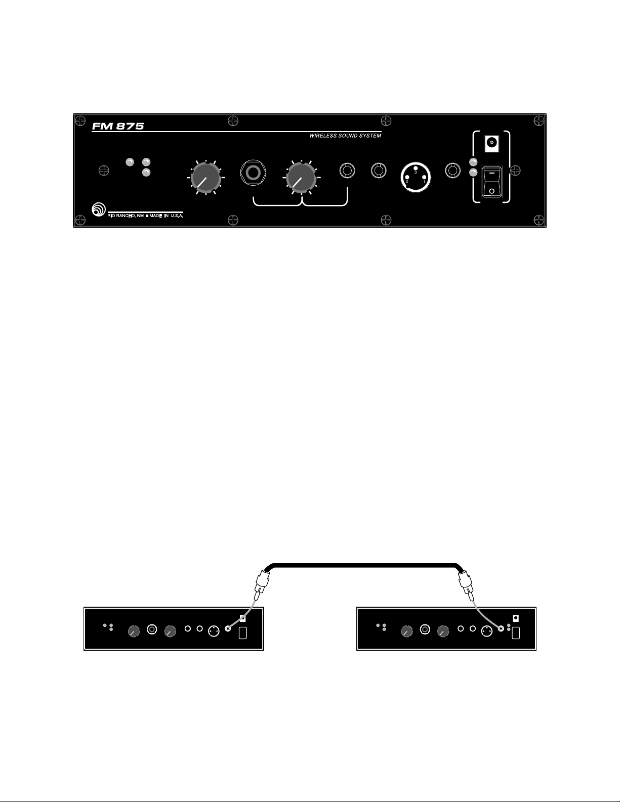
OMNI-BUS IN/OUT: An RCA phono jack that functions both as a line level input and line level output.
This "omnibus" jack is primarily used for interconnecting several FM875s together
for simultaneous operation. This jack can also be used with a tape deck to either
record from or play back into the FM875. When used with a tape deck or other
audio source, the sound output level must be controlled by the volume control on
the tape deck since there is no volume control on the FM875 for this jack.
Male
FM 875 #1 FM 875 #2
– –
OMNI BUS
IN/OUT
RCA
Connect two FM875s
together using the
OMNI-BUS jacks.
Male
RCA
OMNI BUS
IN/OUT
When connected in this manner, the volume control knob on one unit will affect
the loudness of that source (wireless, aux, etc.) on both FM875 systems.
4
Page 5

MIC LEVEL
OUTPUT:
LINE OUT:
AUX IN: An RCA phono jack input used for playback of line level outputs from tape decks,
AUX VOLUME: This control adjusts the volume of the MIC OR AUX IN and the AUX IN inputs.
MIC OR AUX IN: This jack is a standard 1/4" phone jack and will accept a dynamic microphone.
WIRELESS MIC
VOLUME: This control adjusts the volume of the built-in wireless microphone system.
A 3-pin XLR audio connector which provides a balanced, low impedance (200
Ohm), 10 millivolt, microphone level output suitable for house sound systems,
microphone mixers and other units requiring a microphone level input. Pin 1 is
Ground or Shield, pin 2 is Audio High, and pin 3 is Audio Low. If using an
unbalanced load, pin 1 is Ground, pin 2 is Audio and pin 3 is not used. The output
level at this jack varies with the setting of the WIRELESS MIC VOLUME and AUX
VOLUME knobs.
An RCA phono jack that provides a 1 Volt output signal to drive line level inputs of
tape decks, cassette players and other P.A. systems.
cassette players and other P.A. systems.
This
knob does not affect the MODULATION LEDs located near it.
MODULATION LEDs: The -20 and LIMIT Leds continuously indicate the modulation level (audio level) of
the received signal from the transmitter and are used when making initial
adjustments to the transmitter. See items 10 and 11 in the section on
"OPERATING INSTRUCTIONS" on page 10.
RF LED: A green LED lights when the companion transmitter is turned on and there is
sufficient signal for good system operation. Internal circuits monitor both signal
level and interference levels and decide if the transmitted signal is strong and
"clean" enough for satisfactory operation. If not, the RF lamp will go out and the
receiver will "squelch", shutting off the sound output. This action is automatic and
requires no user adjustment.
5
Page 6
TRANSMITTERS
Standard FM-AV4 systems include an M175 belt-pack transmitter which is designed to be used with a
lavalier or headset microphone. If you have one of the other optional Lectrosonics transmitters, consult
the supplied manual for that transmitter for the description and operating instructions.
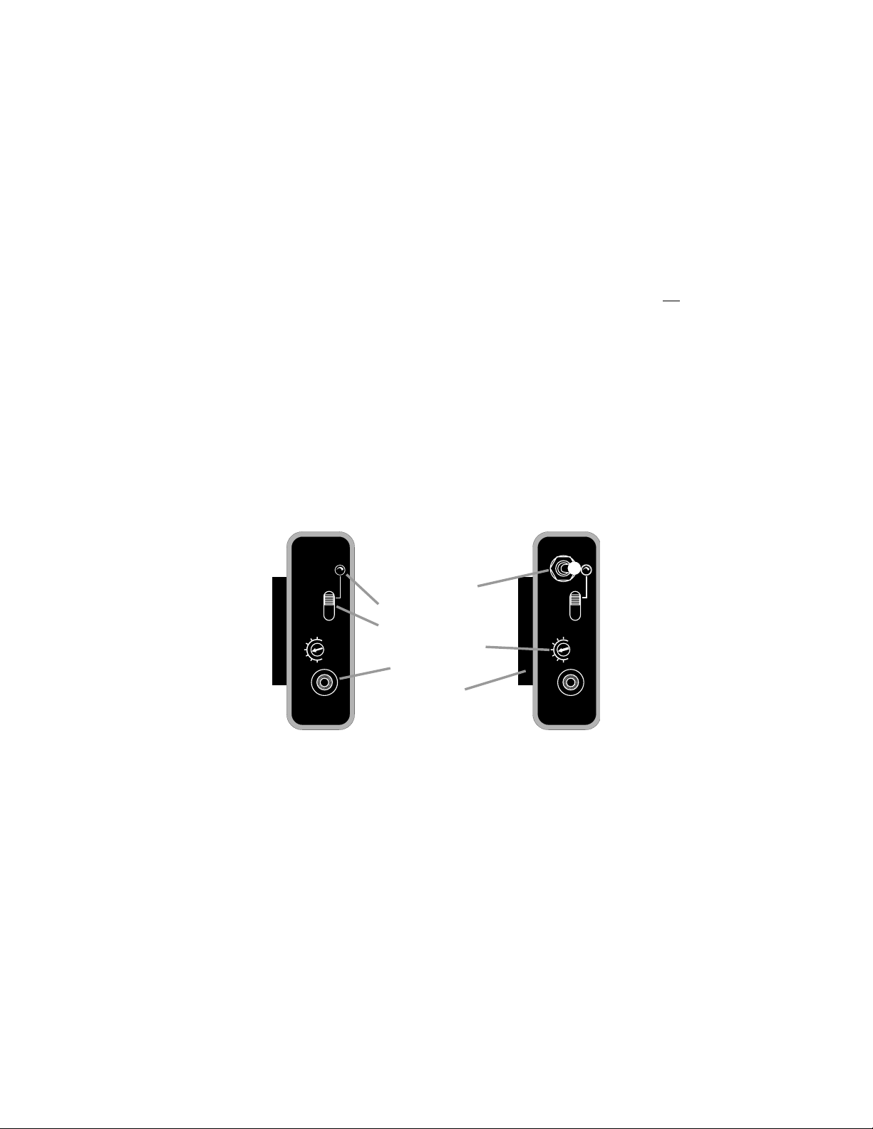
The MIC JACK is a locking micro jack that supplies "phantom power" for electret microphones such as the
Lectrosonics M130, M140 and the HM142V and HM152V headset models. Insert the microphone cord plug
into the jack and rotate it clockwise to lock it. It is important that the plug be securely locked, since the
microphone cord serves as the antenna for the transmitter.
The POWER ON/OFF switch turns the power on and off. The switch should be left in the off position when
the transmitter is not in use. When the switch is in the on position, the battery will be drained even though
the transmitter is not being used.
The BATTERY INDICATOR LAMP will light when the transmitter is turned on and will stay lit as long as
the battery is good. As the battery voltage drops, the lamp will grow dim and finally go out.
The MIC LEVEL is a recessed screwdriver adjustment used to match the gain of the transmitter to different
microphones, individual voices or other audio inputs such as tape deck outputs.
The AUDIO MUTE SWITCH (M175-LS only) is a toggle type on-off switch used to shut off the audio signal
without shutting off the RF carrier of the transmitter.
LECTROSONICS
M175
ON
PWR
OFF
+
MIC
LEVEL
–
MIC
Audio Switch
Battery Indicator Lamp
Power ON/OFF Switch
Mic Level Adjust
Microphone Jack
Belt Clip
M175 Series
AUDIO
OFF
ON
PWR
OFF
+
MIC
LEVEL
–
MIC
LECTROSONICS
M175-LS
6
Page 7

TRANSMITTERS cont’d
The battery you use in the M175 Series transmitter should be a 9 Volt alkaline, available almost
everywhere. An alkaline battery will provide up to 15 hours of operation. Carbon zinc batteries, even if
marked "heavy duty" will only provide about 4 hours of operation. Make sure your batteries are marked
"alkaline." Short battery life is almost always caused by weak batteries or batteries of the wrong type.
The BATTERY LAMP will light when the transmitter is turned on and will stay lit as long as the battery is
good. As the battery voltage drops, the lamp will grow dim and finally go out. Even after the lamp goes
out, there may still be up to an hour or more of operating time remaining. When the battery voltage is too
low for proper transmitter operation, the sound from the wireless system may be distorted, intermittent or
totally absent. When the transmitter is first turned on, the lamp may light for a short while even with a bad
battery. It is good practice to check the brightness of the lamp after the transmitter has been on for several
minutes and to note the brightness occasionally during use.
Open the battery compartment as shown below. Observe the large and small holes in the battery contact
pad before inserting a new battery and orient the battery correctly. Insert the contact end of the battery
first, making sure the contacts are aligned with the holes in the contact pad, and then close the door or
replace the cover.
1
To open the battery
compartment door, push the
door up and away from the
case with your thumb, then
swing open.
M175 Series
2
7
Page 8

SYSTEM SETUP
This section includes some basic steps that will ensure trouble-free operation of your FM-AV4 system:
1) Make sure the transmitter battery is good, or better yet, new.
2) Charge up the battery pack in the FM875 fully before you use the system.
3) The internal antenna is built into the cabinet of the amplifier/speaker unit. Position the FM875 so that
it is not within 3 or 4 feet of large metal surfaces such as air conditioning ducts. It is also good practice
to position the unit so that there is a direct "line of sight" between the transmitter and the FM875.
A wireless transmitter sends a radio signal out in all directions. This signal will often bounce off nearby
walls, ceilings, etc. and a strong reflection can arrive at the receiver along with the direct signal. If the
direct and reflected signals are out of phase with each other, as depicted in the figure below, a partial
or complete cancellation of the received signal will occur. The result will be a "drop out." A drop out
sounds like either a hum or hiss, or in severe cases, may result in a complete loss of the sound when
the transmitter is positioned in certain locations in the room. Moving the transmitter even a few inches
may change the sound of the hum or hiss, or eliminate it. A dropout situation may become either better
or worse as the crowd fills or leaves the room.
In the event that you do encounter a dropout problem, first try moving the FM875 at least 3 or 4 feet
from where it was. This may alleviate the dropout problem. If dropouts are still a problem, try moving
the FM875 to an entirely different location in the room.
TRANSMITTER
PHASE
CANCELLATION
REFLECTIVE SURFACE
DIRECT SIGNAL
INDIRECT SIGNAL
MULTI-PATH DROPOUT
RECEIVER
8
Page 9

SYSTEM SETUP cont’d
4) If you have more than one transmitter on the same frequency, turn on only one transmitter at a time.
You cannot use the two transmitters at the same time with a single FM875. You will need to "alternate"
back and forth between the transmitters. Failure to do so will result in an obnoxious whining sound
from the system, and the audio will probably not be understandable.
5) Use the minimum volume that will enable everyone to hear. It doesn’t have to be loud to be heard.
Placing the FM875 in the back of the room works well in most instances, since this places the speaker
far enough away from the microphone to minimize feedback and close enough to the most distant
listeners to provide adequate sound coverage.
6) The FM875 should be elevated for best coverage. The unit should ideally be at least 2 feet higher than
the audience. For example, with an audience standing on flat ground, the number of people who can
hear clearly will double if you raise the unit from 5 feet above the ground to 7 feet above the ground.
See below for more detailed information on placement of the unit.
7) During actual operation, the FM875 should be aimed so that the sound from the speaker is directed
toward the audience and away from the microphone. This will reduce feedback problems. "Feedback"
is a loud squealing sound coming from the speaker when the volume is too high or the microphone is
too close to the FM875. Feedback is generally more of a problem when using lavalier (lapel) type
microphones than with hand-held or headset type microphones because the microphone is farther from
the mouth. See below for more details on feedback.
8) The standard FM-AV4 system includes an M140 cardioid lavalier microphone. This directional
microphone will minimize background noise and provide resistance to feedback when properly
positioned on the user’s body. Clip the microphone on the lapel or tie as close as possible to the
mouth.If the system is to be used outdoors or near an air conditioner duct, use the foam windscreen
provided with the mic. This will reduce "wind noise" caused by air movement across the microphone.
Refer to the Microphone Choices section on page 11 for optional microphones.
OPERATING TIPS
WHAT ARE THE CAUSES OF FEEDBACK?
Feedback (squealing) occurs when the sound from the speaker re-enters the microphone, comes back out
of the speaker again and re-enters the microphone, and so on. At a given distance between the
microphone and speaker, the sound can only be turned up to a certain loudness before feedback occurs.
Moving the mic further away from the speaker (or the speaker away from the mic) will allow a louder setting
of the sound system.
MAXIMIZING GAIN
1. Place the microphone as close to your mouth as is practical. This will increase the input level for the
microphone so that you are clearly picked up by the mic but background noise will be reduced.
2. Place the speaker (the main unit) as far as you can from where you’ll be speaking and in a position that
will cover your most distant listener.
9
Page 10

OPERATING INSTRUCTIONS
This section covers the initial adjustments to the FM875 and the companion transmitter that must be made
before the system is placed into operation:
1) Connect the audio output cable as required. If you are connecting into a "house" sound system or
external audio or recording equipment, make those connections before turning on the power.
2) Turn both volume controls on the FM875 control panel to minimum (fully counter-clockwise).
3) Set the power switch to ON. Verify that the POWER lamp lights.
4) Position yourself behind the FM875 (or sound system speakers) so that the sound from the speaker
output will be directed away from the microphone.
5) Plug your microphone into the transmitter. Rotate the plug clockwise to make sure the connection is
locked. Do not over-tighten the plug.
6) Turn the transmitter power on and verify that the red light on it lights. If the lamp is very dim or does
not light, replace the battery.
7) Observe that the RF lamp on the FM875 control panel is lighted. This verifies that the unit is receiving
a useable signal from the transmitter.
8) Position the microphone on your person in the same location it will be in during actual operation. The
microphone should ideally be within 6 to 10 inches from the mouth to minimize "feedback".
9) A small screwdriver is supplied with the transmitter. The screwdriver is used to adjust the audio gain
of the transmitter to match the microphone with your voice. The adjustment is made while observing
the MODULATION lamps on the FM875 control panel as shown in the figure on page 10.
10) Speak at the voice level you will be using during actual operation. While speaking, adjust the
transmitter gain until the -20 lamp is lighted or flickers and LIMIT lamp blinks only on the loudest
words. Raise and lower your voice while observing the lamps. The LIMIT lamp should only blink
occasionally.
11) You may now adjust the WIRELESS MIC VOLUME control to a level which will allow everyone in the
audience to hear clearly.
REMEMBER--the transmitter gain control is used only to adjust for proper MODULATION lamp indications.
DO NOT use it to adjust the output volume of the FM875. Different voices and different microphones will
usually require readjustment of the transmitter gain control, so check the adjustment frequently. If several
different people will be using the system and there is not time to make the adjustment for each individual,
adjust it for the loudest voice.
10
Page 11

–
I
OPERATING INSTRUCTIONS cont’d
10
0
2
4 6
8
MODULATION
RF
20
LIM T
WIRELESS MIC
VOLUME
Red LampYellow Lamp
Green
Lamp
USING HARD-WIRED MICROPHONES
Any unbalanced, dynamic microphone can be plugged into the AUX MIC INPUT.
1) Make sure the volume knobs are set at "0."
2) Plug an auxiliary cord (a MM-16 or MC-16C will work) into your microphone and into the MIC OR AUX
IN.
3) Flip the switch on the microphone and bring the AUX VOLUME up slowly to the desired volume. If
the speaker squeals, the microphone is too close to the speaker. A longer microphone cord will
reduce this noise.
TAPE RECORDING AND PLAYBACK
1) To record, connect the LINE OUT on the unit with the AUDIO IN (line input) on the tape recorder.
2) To playback, connect the AUX IN on the unit with the AUDIO OUT (line level) on the tape recorder.
Set the AUX VOLUME at about "6" then adjust the volume control on your tape player to get the
desired volume.
Not all tape recorders will work with the FM-AV4. Low cost tape recorders may not have "line level"
inputs and outputs required for quality recording and playback.
CONNECTING INTO HOUSE SOUND SYSTEMS
1) Connect MIC LEVEL OUTPUT to the house sound system. This should be a balanced microphone
level input with an XLR connector.
2) The volume of the MIC LEVEL OUTPUT is controlled by both the AUX VOLUME and the WIRELESS
MIC VOLUME depending on what audio source you are using. If using only one source, be sure to
turn the unused volume control to 0.
11
Page 12

MICROPHONE CHOICES
M140 - This is the microphone supplied with the standard FM-AV4 system. It is a cardioid (directional)
microphone for lavalier ("lapel") use. Due to the directional pickup pattern, this model will generally provide
more gain (loudness) before feedback than the M130 omni-directional model. The M140 has a "brighter"
sound than the M130 (the treble is boosted). This brighter sound normally improves the clarity that is
sometimes lost with lavalier type microphones. The M140 is subject to wind noise and generally works best
indoors, however, it is supplied with a foam windscreen which helps to reduce noise caused by wind.
M130 - This is a very small, omni-directional mic used as a lavalier ("lapel") microphone. It may be prone
to feedback since it is usually placed so far away from the users mouth; however, it has a very flat
response and excellent tone quality. As is true of most omni-directional type microphones, the M130 is
very free from wind noise and clothing "rattle".
M121S - This is a cardioid, dynamic, hand-held microphone. It can be plugged directly into the MIC OR
AUX IN jack on the control panel of the FM875 using a standard microphone cord (MM-16 or MC-16C).
The M121S is available as an accessory item.
HM142V - This single-band headset microphone is normally worn on the head, but can also be worn
around the neck for hands-free operation. It provides maximum gain before feedback since the microphone
is very close to the user’s mouth. The built-in volume control helps control feedback in difficult
environments, such as when the user must move in close to the FM875 speaker. Worn on the head, the
microphone will remain at a constant distance from the user’s mouth, which keeps the volume of the sound
system constant as the head moves.
HM152V - A double-band headset microphone intended to be worn on the head. The pickup element and
tonal characteristics are the same as the single-band HM142V, but it is more securely mounted and in most
cases, more comfortable, due to the fully adjustable dual headband. The same volume control is provided
to help control feedback.
The best matched microphones are:
For hand-held use:
M121S dynamic cardioid, with ON/OFF switch
For headset use:
HM142V single headband model
HM152V double headband model
For lavalier use:
M140-micro
Other brands of microphones may be used, provided they are the correct type, with an appropriate
connector. Consult the factory or your dealer if you are not sure.
12
Page 13

TROUBLESHOOTING
Before going through the following chart, be sure that you have a good battery in the transmitter. It is
important that you follow these steps in the sequence listed.
SYMPTOM POSSIBLE CAUSE
FM875 POWER LAMP NOT ON OR DIM 1) Power switch in OFF position
2) Batteries completely discharged
3) Battery connections loose
TRANSMITTER BATTERY LED OFF 1) Transmitter power switch off.
2) Battery is inserted backwards.
3) Battery is dead.
FM875 RF LAMP OFF 1) Transmitter not turned on.
2) Transmitter battery is dead.
3) Transmitter and receiver not on same frequency.
Check labels on transmitter and receiver.
4) Operating range is too great.
NO SOUND AND RECEIVER MOD LEVEL LEDs ARE OFF
1) Transmitter is not getting an audio signal.
2) Defective mic or mic cable.
3) Transmitter gain control set much too low.
4) Transmitter audio muted. Check to see that the
audio is not muted on your transmitter, if this feature
is available on your model transmitter.
NO SOUND BUT RECEIVER MOD LEVEL LEDs ARE ON
1) WIRELESS or AUX VOLUME control turned
completely down.
2) Sound system or recorder input is turned down.
3) Defective speaker
DISTORTED SOUND 1) Transmitter gain (audio level) is too high. Speak into
the transmitter and check mod level lamps on
transmitter and receiver. See page 9.
2) Receiver output may be mis-matched with the sound
system or recorder input.
3) Excessive wind noise or breath "pops."
4) FM875 batteries very low - recharge.
HISS AND NOISE -- AUDIBLE DROPOUTS 1) Transmitter gain (audio level) too low.
2) Operating range too great.
EXCESSIVE FEEDBACK 1) Transmitter gain (audio level) too high. Check gain
adjustment and/or reduce receiver output level.
2) Microphone too close to speaker system. Move
transmitter closer to the user’s mouth.
13
Page 14

ACCESSORIES AND REPLACEMENT PARTS
ITEM DESCRIPTION
CH-40 Battery Charger
HM142V Single headband
Headset Microphone
HM152V Double headband
Headset Microphone
M121S Dynamic Microphone
MC-16C Microphone Cord
MM-16 Microphone Cord
MM-36 Audio Patch Cord
RK-51 Wind Screen
RK-119 Wind Screen
RK-142 Wind Screen
USE
Replacement
With locking micro plug
With locking micro plug
For hand-held use plugged into the AUX MIC
INPUT jack of the FM875 (cord not supplied).
16 ft. coiled cord (1/4" male to male) for M121S
Straight cord (1/4" male to male) for M121S
36" RCA (male to male) for interconnecting
HI LEVEL IN and OUT jacks with other equipment.
For M121S microphone
For M140 microphone
For HM142V and HM152V headset microphones
14
Page 15

SPECIFICATIONS
OVERALL FM-AV4 SYSTEM
Operating frequency: 169 to 186 MHz
Wireless operating range: Up to 750 feet
FM deviation: ±15 KHz
Distortion: less than 1%
AMPLIFIER
Audio power output: 9 Watts, RMS
Amplifier freq. response: 50 Hz to 20 KHz
Speaker: 8" full range cone
Audio outputs: XLR - 200 Ohm, balanced;
Audio inputs: RCA - high level "line"
Power supply: Two 6 Volt "gel-cell" batteries
Operating time per charge: 12 to 15 hours typical
FM875 RECEIVER
Sensitivity: -110 dBm for 20 dB Sinad (0.7 uV)
RF signal-to-noise ratio: 96dB flat, 100dB A-weighted
Squelch quieting: Greater than 100dB
AM rejection: Below the noise at all input levels
Spurious/image rejection: Greater than 100dB
M175 SERIES TRANSMITTERS
Operating frequencies: 169 to 186 MHz
RF Power Output: 50 mW
Deviation: ±15kHz
Spurious Radiation: 50dB below carrier
Frequency Stability: ±0.005%
Equivalent Input Noise: -123dB
Input Sensitivity: 8mV to 1.6V for full modulation
Input Compressor: Soft Compressor; 12dB range
Electret Bias: +5 Volt DC (positive bias)
Antenna: Input cord or microphone body
Input Jacks: Twist-lock micro for electret microphones
Battery Indicator: LED indicates battery condition
Battery Life: Approximately 15 hours
Controls: Power on/off slide switch
Size: 1.3 x 2.35 x 3.7 inches
Weight: 6.6 ozs with battery and microphone
FCC ID: DBZM175 (150-172 MHz)
Emission designator: 58K0F3E
100 mV maximum
RCA-1kOhm,1Voltmaximum
1/4" - dynamic mic
Recessed audio gain control
Mute on/off toggle switch (M175-LS only)
DBZM175A (174-216 MHz)
15
Page 16

SERVICE AND REPAIR
If your system malfunctions, you should attempt to correct or isolate the trouble before concluding that the
equipment needs repair. Make sure you have followed the setup procedure and operating instructions.
Check out the inter-connecting cords and then go through the TROUBLE SHOOTING section in the manual
We strongly recommend that you do not try to repair the equipment yourself and do not have the local
repair shop attempt anything other than the simplest repair. If the repair is more complicated than a broken
wire or loose connection, send the unit to the factory for repair and service. Don’t attempt to adjust any
controls inside the units. Once set at the factory, the various controls and trimmers do not drift with age
or vibration and never require readjustment. There are no adjustments inside that will make a
malfunctioning unit start working.
LECTROSONICS service department is equipped and staffed to quickly repair your equipment. In-warranty
repairs are made at no charge in accordance with the terms of the warranty. Out of warranty repairs are
charged at a modest flat rate plus parts and shipping. Since it takes almost as much time and effort to
determine what is wrong as it does to make the repair, there is a charge for an exact quotation. We will
be happy to quote approximate charges by phone for out of warranty repairs.
RETURNING UNITS FOR REPAIR
You will save yourself time and trouble if you will follow the steps below:
A. DO NOT return equipment to the factory for repair without first contacting us by letter or by phone. We
need to know the nature of the problem, the model number and the serial number of the equipment.
We also need a phone number where you can be reached 8 am to 4 pm (Mountain Standard Time).
B. After receiving your request, we will issue you a return authorization number (R.A.). This number will
help speed your repair through our receiving and repair departments. The return authorization number
must be clearly shown on the outside of the shipping container.
C. Pack the equipment carefully and ship to us, shipping costs prepaid. If necessary, we can provide you
with the proper packing materials. UPS is usually the best way to ship the units. Heavy units should
be "double-boxed" for safe transport.
D. We also strongly recommend that you insure the equipment, since we cannot be responsible for loss
of or damage to equipment that you ship. Of course, we insure the equipment when we ship it back
to you.
Mailing address: Shipping address: Telephones:
Lectrosonics, Inc. Lectrosonics, Inc. (505) 892-4501
PO Box 15900 581 Laser Rd. (800) 821-1121
Rio Rancho, NM 87174 Rio Rancho, NM 87124 FAX: (505) 892-6243
USA USA
World Wide Web: http://www.lectrosonics.com email: sales@lectrosonics.com
16
Page 17

Page 18

LIMITED ONE YEAR WARRANTY
The equipment is warranted for one year from date of purchase against
defects in materials or workmanship provided it was purchased from an
authorized dealer. This warranty does not cover equipment which has
been abused or damaged by careless handling or shipping. This warranty
does not apply to used or demonstrator equipment.
Should any defect develop, we will, at our option, repair or replace any
defective parts without charge for either parts or labor. If we cannot
correct the defect in your equipment, we will replace it at no charge with
a similar new item. We will pay for the cost of returning your merchandise
to you.
This warranty applies only to items returned to us, shipping costs prepaid,
within one year from the date of purchase.
This warranty gives you specific legal rights. You may have additional
legal rights which vary from state to state.
LECTROSONICS, INC.
581 LASER ROAD
RIO RANCHO, NM 87124 USA July 7, 1999
 Loading...