

Page 1

DSQD
DIGITAL WIRELESS
4 Channel Digital Receiver
INSTRUCTION MANUAL
Fill in for your records:
Serial Number:
Purchase Date:
Rio Rancho, NM, USA
www.lectrosonics.com
Page 2

DSQD Manual
Table of Contents
Introduction ........................................................................... 2
General Technical Description ............................................2
Encryption ............................................................................ 2
Digital Hybrid Wireless
LCD Screen ......................................................................... 3
Diversity Reception .............................................................. 3
Infrared Sync ........................................................................ 3
What is Dante? .................................................................... 3
Panels and Features ..............................................................4
DSQD Front Panel ............................................................... 4
DSQD Rear Panel ................................................................ 4
IR (infrared) Port .................................................................. 5
USB Port .............................................................................. 5
Headphone Volume Adjustment ........................................... 5
Channel Selector Buttons .................................................... 5
Dante Ports (if Dante module is installed) ............................ 5
Ethernet Port ........................................................................ 5
Multi-Frame Communication ................................................ 5
Power Inlet ........................................................................... 5
LCD Menu Map ....................................................................... 6
Navigating the Menus ........................................................... 8
RF Setup Menu ...................................................................... 8
RF Frequency ......................................................................8
Frequency Scan ................................................................... 8
Group Tune .......................................................................... 9
Group Tune Setup ................................................................ 9
Diversity Setup ..................................................................... 10
Audio Setup Menu ................................................................. 12
Audio Level .......................................................................... 12
Audio Polarity ....................................................................... 12
Smart Noise Reduction ........................................................ 12
Compatibility Modes ............................................................. 12
Talkback Setup ..................................................................... 12
IR Sync & Encryption Menu .................................................. 13
Encryption Key Management ............................................... 13
Encryption Keys ................................................................... 13
Sync Settings ....................................................................... 13
Tools and Settings Menu ......................................................14
RX On/Off ............................................................................ 14
TX Battery Type ................................................................... 14
Front Panel Setup ................................................................ 14
Antenna Bias Power ............................................................. 14
Network Settings ................................................................. 14
Edit Names .......................................................................... 15
Restore Defaults ..................................................................15
Pilot Tone Bypass ................................................................. 15
About .................................................................................... 15
Links ..................................................................................... 15
Specifications and Features ................................................. 15
Wireless Designer Software ................................................ 15
Firmware Update Instructions .............................................. 15
Supplied Hardware ................................................................ 16
Unpacking the Unit ............................................................... 16
Items Included in the Box: .................................................... 16
Optional Accessories ............................................................ 17
Installing two DSQD Receivers into a SingleRack Space .. 18
Service and Repair ................................................................ 20
Returning Units for Repair ................................................... 20
®
Technology .................................... 3
Introduction
The latest digital radio technology is employed in the
DSQD receiver to set a new standard for performance
and flexibility. Four discrete audio channels are packed
into a single half-rack chassis, with balanced analog
and Dante® digital network outputs. The receiver tunes
continuously across the UHF band from 470.100 to
614.375 MHz.
The digital architecture delivers studio quality audio with
ultra-low latency. The receiver includes an extended
operating range rivaling the best analog and Digital
Hybrid Wireless® systems with tracking filters that stay
centered on the selected frequency.
The DSQD is also backward compatible with any Digital
Hybrid Wireless® transmitters including the SM Series,
LT, HM Series, SSM, HH Series, UM400, UM400a, LM
Series, MM Series, and WM.
The receiver provides a USB port for firmware updates, an IR port for fast setup and an ethernet port for
control. A large, high resolution, backlit LCD and large
membrane switches provide an intuitive interface that is
highly visible in daylight or dimly lit conditions.
Wireless Designer™ software integrates the digital and
Digital Hybrid Wireless into a single control panel with
site scanning and frequency coordination. The software
is free and can be used while connected to equipment
or offline in planning a multi-channel system.
Antenna ports on the rear panel accept input from
remote antennas, with a “loop-thru” output to another
mainframe using the internal multicoupler. A kit is also
available to mount antenna inputs (BNC connectors) on
the front panel.
General Technical
Description
Encryption
When transmitting audio, there are situations where
privacy is essential, such as during professional sporting events, in court rooms or private meetings. For
instances where your audio transmission needs to be
kept secure, without sacrificing audio quality, Lectrosonics implements AES256 encryption in our digital wireless microphone systems. High entropy encryption keys
are first created by the DSQD Receiver. The key is then
synced with an encryption-capable digital transmitter,
via the IR port. The audio will be encrypted and can
only be decoded if both DSQD and transmitter have the
matching encryption key. If you are trying to transmit
an audio signal and keys do not match, all that will be
heard is silence.
2
LECTROSONICS, INC.
Page 3

Digital Receiver
Digital Hybrid Wireless® Technology
All wireless links suffer from channel noise to some degree, and all wireless microphone systems seek to minimize the impact of that noise on the desired signal. Conventional analog systems use compandors for enhanced
dynamic range, at the cost of subtle artifacts (known as
“pumping” and “breathing”). Wholly digital systems defeat
the noise by sending the audio information in digital form.
To support the installed base of Digital Hybrid Wireless
systems, the DSQD receiver includes DSP algorithms
for compatibility with Digital Hybrid Transmitters.
The DSQD receiver uses a DSP generated ultrasonic
pilot tone to reliably mute the audio when no RF carrier
is present. The pilot tone must be present in conjunction with a usable RF signal before the audio output
will be enabled. 256 pilot tone frequencies are used
across each 25.6 MHz block within the tuning range of
the system. This alleviates erroneous squelch activity in
multichannel systems where a pilot tone signal can appear in the wrong receiver via IM (intermodulation).
LCD Screen
Easy navigation of all setup parameters is provided by a
full color, backlit LCD screen and membrane push buttons. The high resolution display provides comprehensive monitoring of all receiver parameters.
Diversity Reception
Three different receiver diversity schemes can be
employed depending on the needs of the application,
including antenna switching (during packet headers
for seamless audio), Digital Ratio Diversity, or Digital
Frequency Diversity.
Infrared Sync
The DSQD has a bi-directional IrDA interface which
allows quick syncing of settings and encryption keys to
transmitters with the push of a button. The receiver also
offers tuning groups to allow the user to set up a list of
frequencies, allowing for easy tracking of frequency tuning in the transmitters.
What is Dante?
Audinate’s patent pending Dante™ technology is a
flexible Internet Protocol (IP) and Ethernet based digital
AV network technology that eliminates the many bulky
cables needed to provide point-to-point wiring for analog AV installations.
With Dante, existing infrastructure can be used for high
performance audio as well as for ordinary control, monitoring or business data traffic. Digital networks utilize
standard IP over Ethernet offering high bandwidth capable of transporting hundreds of high quality channels
over Gigabit Ethernet.
Set-up and configuring the system is made easy as
well, saving enormous installation costs and long term
cost of ownership on a digital network. The physical
connecting point is irrelevant: audio signals can be
made available anywhere and everywhere. Patching
and routing now become logical functions configured in
software, not via physical wired links.
Summary of Dante Benefits
• Plug-and-play technology – automatic discovery
and simple signal routing
• Reduced Cost & Complexity- No special skills
required to set up audio networking
• Sample accurate playback synchronization
• Add/remove/rearrange components at will
• Deterministic latency throughout the network
• Support mixed bit depths and mixed sample
rates over one network
• Scalable, flexible network topology supporting a
large number of senders and receivers
• Supports 1Gbps networks
• Supports a single integrated network for audio,
video, control, monitoring
• Uses inexpensive, off-the-shelf computer
networking equipment
Rio Rancho, NM
3
Page 4

DSQD Manual
Panels and Features
DSQD Front Panel
Menu/Select
Reset Button
Return to
previous screen
Menu navigation
buttons
Antenna Bias
Power LEDs
Headphone Volume
Adjustment
DSQD Rear Panel
Dante Ports
Headphone Jack
Antenna B Input
50 Ohm BNC
Antenna B
Loop-thru Output
50 Ohm BNC
Channel Selector Buttons
XLR Analog Output
Connectors
USB Port
Power Inlet
Multi-Frame
Communication
IR Port
Ethernet
Port
Power switch
Antenna A Input
50 Ohm BNC
Antenna A
Loop-thru Output
50 Ohm BNC
4
LECTROSONICS, INC.
Page 5

Digital Receiver
IR (infrared) Port
Frequency and settings can be transferred to and from
the DSQD receiver via this port to an IR enabled transmitter to simplify setup.
USB Port
For firmware updates and connection to Wireless Designer software.
Reset Button
For MCU recovery in the event of an interrupted firmware update.
Headphone Volume Adjustment
Adjusts the monitor loudness of the output channel
selected with the numbered buttons below the LCD.
Antenna Bias LEDs
Glow green with antenna bias power is turned on.
Channel Selector Buttons
From the main screen, pressing a Channel Selector
Button will show a detailed transmitter screen (see
Quick Start for more information).
From the Sync Settings screen, pressing a Channel
Selector Button will initiate a sync with the transmitter
via the IR port.
Antenna Loop-thru
For multiple DSQD installations in a rack, a “loop-thru”
is available to feed two or three receivers from a single
antenna pair. Connect coaxial cables from the multicoupler loop-thru outputs on the first receiver to the antenna loop-thru inputs on the next receiver in the stack.
WARNING: Do not enable antenna power if
connecting antenna loop-thru outputs on one
receiver to the antenna inputs on another
receiver.
Dante Ports (if Dante module is installed)
Connects to a Dante digital audio network.
Ethernet Port
Used for setup, monitoring and control with Wireless
Designer software or 3rd party control systems connected via a network.
Power Inlet
The locking DC coaxial inlet requires 7-18 VDC and
draws 2.5A maximum.
Operating Instructions
To begin using the DSQD quickly, follow the steps below. The other settings can be adjusted as needed.
1. Set Channel Frequency: Assign a frequency to
each channel, which will correlate to the accompanying Channel Selector Button (1-4). From
the Quick Access Menu or the RF Setup Menu,
manually set frequency on the RF Frequency
screen or scan for available frequencies and assign
a frequency to each channel from the Frequency
Scan screen.
2. Set Compatibility Mode: From the Quick Access
Menu or the Audio Setup Menu, set compatibility
modes for each channel.
3. Set Encryption Keys: From the IR Sync & En-
cryption Menu, select a key type and then create a
key (if needed).
NOTE: See Encryption Key Management for
more instruction.
4. Sync Settings: From the Quick Access Menu or
the IR Sync & Encryption Menu, initiate sync for
each channel via the IR port. Hold the target transmitter close to the IR port on the front panel of the
DSQD. Select SEND ALL. A message will appear
on the main screen letting you know the sync was
successful. Messages will appear letting you know
if the sync was successful.
NOTE: See Sync Settings for more instruction.
5. You can also quickly check a channel’s status by
pressing a Channel Selector Button from the
DSQD home screen. This screen allows you to
change frequency and turn Group Tune on/off. In
addition, you can check the status of the compatibility mode, diversity setting, transmitter battery
status, audio level and audio mute status.
Carrier
frequency
Group Tune
On/Off
Diversity
Setting
Audio
Level
Mute
On/Off
Multi-Frame Communication
Allows offline, multi-frame communication and frequency coordination (coming soon).
Rio Rancho, NM
Compatibility
Mode
Transmitter
Battery Status
RF Level
with 10 seconds
of history
Channel Selector
Buttons
5
Page 6

DSQD Manual
LCD Menu Map
Quick
Menu
RF FREQUENCY
FREQUENCY SCAN
GROUP TUNE
SYNC
SETTINGS
COMPATIBILITY
MODES
RF FREQUENCY
FREQUENCY SCAN
SEL
SEL
SEL
SEL
SEL
SEL
SEL
BACK
BACK
BACK
BACK
BACK
BACK
BACK
Press SEL to
select desired
channel
Press SEL to
select desired
function
Press SEL to
select desired
channel
Press SEL to
select desired
channel
Press SEL to
select desired
channel
Use arrow keys to
highlight desired
command
Use arrow keys to
highlight desired
command
Use arrow keys
to enable or
adjust
Use arrow keys
to adjust setting
Use arrow keys
to select tuning
group
Press SEL to
select desired
function
Use arrow keys to
select desired
compatibility mode
Use arrow keys
to enable or
adjust
Press SEL to
select scan
setting
RF
Setup
Audio
Setup
GROUP TUNE
GROUP TUNE
SETUP
DIVERSITY
SETUP
AUDIO LEVEL
AUDIO POLARITY
SMART NOISE
REDUCTION
COMPATIBILITY
MODES
SEL
SEL
SEL
SEL
SEL
SEL
SEL
BACK
BACK
BACK
BACK
BACK
BACK
BACK
Press SEL to
select desired
channel
Use arrows to
select desired
function
Press SEL to
select desired
channel
Press SEL to
select desired
channel
Press SEL to
select desired
channel
Press SEL to
select desired
channel
Use arrow keys to
select desired
group/parameter
Use arrow keys
to select tuning
group
Press SEL to
select setting
Press SEL to
select setting
Use arrow keys
to adjust audio
output level
Use arrow keys
to select desired
audio setting
Use arrow keys
to select noise
reduction setting
Use arrow keys to
select desired
compatibility mode
TALKBACK
SETUP
6
SEL
BACK
Press SEL to
select desired
channel
Use arrow keys to
select desired
talkback function
LECTROSONICS, INC.
Page 7

Digital Receiver
IR Sync &
Encryption
SYNC SETTINGS
SYNC KEY
ENCRYPTION KEY
MANAGEMENT
RX ON/OFF
TX BATTERY
TYPE
TX BATTERY
TIMER ALERT
FRONT PANEL
SETUP
SEL
SEL
SEL
SEL
SEL
SEL
SEL
BACK
BACK
BACK
BACK
BACK
BACK
BACK
Use arrow keys to
highlight desired
command
Use arrow keys to
highlight desired
command
Use arrow keys to
select encryption
key
Press SEL to
select desired
channel
Press SEL to
select desired
channel
Press SEL to
select desired
channel/function
Press SEL to
select desired
channel
Press SEL to
select desired
function
Press SEL to
select desired
function
Press SEL to
confirm
selection
Use arrow keys
to select RX
power on/off
Use arrow keys
to select battery
type
Use arrow keys
to select settings
Use arrow keys
to select desired
setting
Tools &
Settings
DANTE POWER
ENABLE
ANTENNA
BIAS POWER
NETWORK
SETTINGS
EDIT NAMES
RESTORE
DEFAULTS
PILOT TONE
BYPASS
ABOUT
SEL
SEL
SEL
SEL
SEL
SEL
SEL
BACK
BACK
BACK
BACK
BACK
BACK
BACK
Press SEL to
select choose
antenna
Press SEL to
select desired
function
Press SEL to
select desired
name
Press SEL to
select desired
function
Use arrow keys
to enable or
disable Dante
Use arrow keys
to select yes or
no
Use arrow keys
to enable or
disable power
Use arrow keys
to adjust setting
Use arrow keys
to edit names
Press SEL to
restore default
settings
Use arrow keys
to adjust setting
Rio Rancho, NM
LINKS
SEL
BACK
Use phone to scan QR code for more information
7
Page 8

DSQD Manual
Navigating the Menus
All Setup Menu items are arranged in a vertical list on
the LCD. Press MENU/SEL to enter the menu, then
navigate with the UP and DOWN arrows to highlight the
desired setup item.
NOTE: To guarantee chosen parameters are
saved, exit a setup screen BEFORE powering
down DSQD.
Press MENU/
SEL to enter
the menu
Press MENU/SEL
to enter the setup
of the highlighted
item
Press the UP and DOWN arrows
to navigate and highlight the
desired menu item
Press the UP and DOWN arrows
to navigate and highlight the
desired item
RF Setup Menu
RF Frequency
Allows manual selection of the operating frequency for
each channel.
NOTE: Display varies with compatibility mode
selection.
Frequency Scan
1. To begin, press MENU/SEL to start the scan.
NOTE: All four channels scan at the same time.
You can also select individual channels for
scanning by pressing the channel selector buttons.
2. Once the scan has completed, use UP and DOWN
arrows to navigate to ZOOM, then press MENU/
SEL.
Press BACK to return to the previous
screen and save selected settings
Quick Access Menu
The quick access menu is a list of menu items grouped
together for DSQD quick start:
• RF Frequency • Sync Settings
• Frequency Scan • Compatibility Modes
• Group Tune
3. Press one of the four channel selector buttons. The
word TUNING will flash on the screen to let you
know you are tuning. Press the UP and DOWN arrows to tune the channel into the area of lowest RF
activity.
Press BACK to save
frequency to channel
8
LECTROSONICS, INC.
Page 9
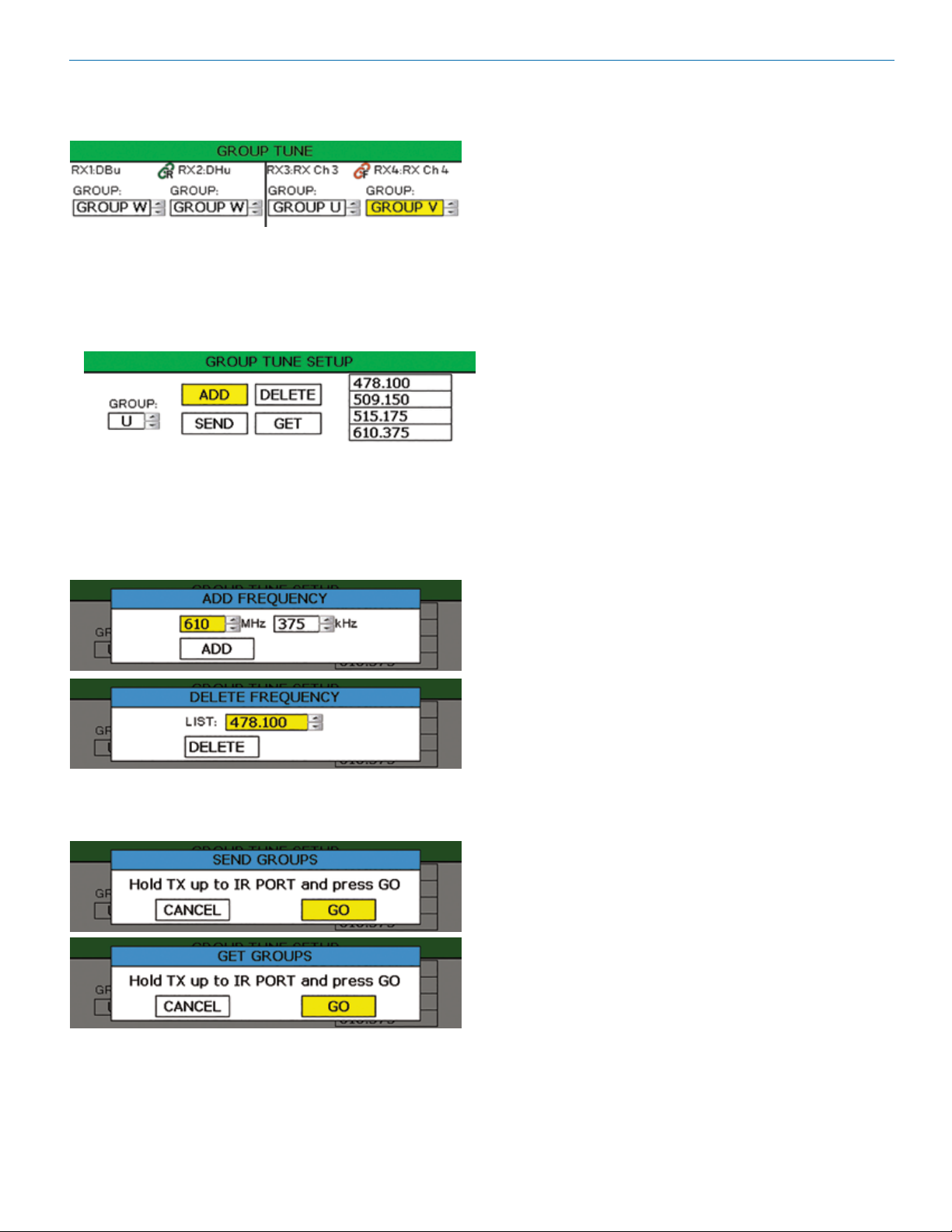
Group Tune
Assign a tuning group to a channel.
Group Tune Setup
Tuning groups allow the user to set up a list of frequencies, allowing for easy tracking of frequency tuning in
the transmitters. Use MENU/SEL to move through the
options and UP arrow to make a selection.
• Four tuning groups are available, U, V, W, X.
• Each group has the option to add or delete a frequency from the list on the right. Use the UP and
DOWN arrows to change frequencies, MENU/SEL
to move through the options, and the UP arrow to
select ADD or DELETE. Push the BACK button to
return to the Group Tune Setup Screen.
Digital Receiver
• Each group can store up to 32 frequencies.
• The user can then choose to send or get (sync) a
frequency.
When a tuning group is assigned, the frequency control
is limited to the frequencies contained in the tuning
group. It also limits the available frequencies in the
frequency coordination process.
Rio Rancho, NM
9
Page 10

DSQD Manual
Diversity Setup
Diversity is a DSQD feature that safeguards against loss of audio signal caused by RF interference or by power loss
in a transmitter. The DSQD architecture allows three different types of diversity reception. Once chosen, the diversity
mode is shown on other screens with a link icon. (Visit the DSQD page on lectrosonics.com for a video with more
details on Diversity.)
Ratio Diversity
Icon
Frequency Diversity
Icon
• Switched: Of the two antennas available on the DSQD, the receiver selects the antenna with the best signal. In
this mode, there are four receivers available.
• Ratio: In this mode, two receiver channels can be “paired” as one receiver. Either Channels 1 and 2 or channels 3
and 4 can be combined into a pair. One receiver in a pair is fixed on Antenna A and the other receiver in a pair is
fixed on Antenna B. The DSQD automatically uses whichever receiver’s RF signal quality is better.
10
LECTROSONICS, INC.
Page 11

Digital Receiver
• Frequency: Again, the receiver channels are paired. In this mode, each channel is set to a different frequency. The
DSQD automatically uses whichever receiver’s RF signal quality is better. The use of separate frequencies helps
minimize dropouts caused by multi-path phenomenon. This technique uses both switched and ratio diversity for
maximum effectiveness.
NOTE: To maximize frequency diversity, choose frequencies separated as far apart as possible.
When using Frequency Diversity, performance can be optimized by using a calibration technique to balance the audio
levels between the two transmitters in the pair. Follow these steps:
1. Plug headphones into the DSQD front panel monitor jack.
2. Select CALIBRATE on the Diversity Setup screen.
3. The Calibrate TX Gain pop-up screen will appear.
4. Adjust the microphone gain on each transmitter to balance the audio level while observing the green bar on the
screen. When audio level is balanced, the green bar is minimized.
WARNING: Use caution when calibrating. Resulting headphone volume may be very loud.
WARNING: Transmitter gain should also be set in accordance with transmitter manual to achieve correct
modulation.
Rio Rancho, NM
11
Page 12

DSQD Manual
Audio Setup Menu
Audio Level
Set audio output level with the level control. The mute
button is a toggle used to mute or unmute the audio
output. The TONE check box is used to generate a
1 kHz test tone at the audio output.
Audio Polarity
Select normal or inverted polarity for each
audio channel.
Smart Noise Reduction
Three levels of noise reduction are available: High,
Normal and Off.
NOTE: Smart Noise Reduction is only available for
digital hybrid compatibility modes.
Compatibility Modes
Multiple compatibility modes are available to match various transmitter types.
The following modes are available:
• D2: Encrypted digital wireless channel
• DUET CH1: To receive Channel One audio from a
Duet transmitter
• DUET CH2: To receive Channel Two audio from a
Duet transmitter
• NA HYB: Legacy digital hybrid mode
• EU HYB: Used only for certain digital hybrid transmitters marketed in the European union
• NU HYB: Digital hybrid mode for current Lectrosonics transmitters
• JA HYB: Used only for certain digital hybrid transmitters marketed in Japan
Talkback Setup
Talkback is a special function that re-directs the audio
output of the transmitter in use to a different receiver
output when talkback is selected on the transmitter. The
normal use is to provide a “com” channel so the person
using the transmitter can have a direct line to the crew
or production staff. When selected, the audio will appear at the designated talkback channel rather than the
channel used for program audio.
12
LECTROSONICS, INC.
Page 13

IR Sync & Encryption Menu
Encryption Key Management
The DSQD has three options for encryption keys:
• Standard: This is the highest level of security.
The encryption keys are unique to the DSQD and
there are only 256 key instances available to be
transferred to a transmitter. The receiver tracks the
number of keys generated and the number of times
each key is transferred. Once a Standard key has
been transferred 256 times, you will be alerted that
a new key must be created.
• Shared: There are an unlimited number of
shared keys available. Once generated by the
DSQD and transferred to a transmitter, the encryption key is available to be shared (synced) by the
transmitter with other transmitters/receivers via the
IR port.
• Universal: This is the most convenient encryption option available. All encryption-capable
Lectrosonics transmitters and receivers contain
the Universal Key. The key does not have to be
generated by the DSQD. Simply set a Lectrosonics encryption-capable transmitter and the DSQD
to Universal, and the encryption is in place. This
allows for convenient encryption amongst multiple
transmitters and receivers, but not as secure as
creating a unique key.
Digital Receiver
3. A message will pop up on the screen warning the
user that all transmitters will need a new key. Select
OK. The creation of a new key is confirmed.
4. Sync new key with transmitter (see Sync Key). The
transmitted audio will then be encrypted with the
new key.
Sync Settings
Allows sending or retrieving setup data via the IR port.
Sync options: Choose to send frequency, send all
settings, retrieve (get) frequency from a transmitter
or retrieve (get) all settings from a transmitter.
Choose Transmitter: Choose one of four Rx chan-
nels by using the Channel Selector Buttons, 1, 2,
3 or 4.
Encryption Keys
The DSQD generates high entropy encryption keys to
sync with encryption-capable transmitters. The user
must select a key type and create a key in the DSQD,
and then sync the key with a transmitter.
1. Begin by selecting a key type.
2. The DSQD will then display a warning to indicate
that there is NO KEY! Select CREATE KEY to
generate a new key.
NOTE: You must position the transmitter’s IR port
directly in front of the DSQD IR port, as closely as
possible, to guarantee a successful sync.
Sync Key
Send or retrieve (get) encryption keys.
NOTE: When Universal Key type is selected, there
is no prompt to create key. See Encryption Key
Management for more information.
Rio Rancho, NM
13
Page 14

DSQD Manual
Tools and Settings Menu
RX On/Off
Use UP and DOWN arrows to toggle power on and off.
TX Battery Type
Set battery type for each channel. Use MENU/SEL to
set and move cursor and the UP and DOWN arrows to
change values.
TX Battery Timer Alert
Set transmitter battery timer alerts for each channel.
Choose to enable/disable alert, set time in hour and
minutes and reset timer. Use MENU/SEL to set and
move the cursor and the UP and DOWN arrows to
change values.
Front Panel Setup
Front panel settings may be customized as follows:
• LCD brightness: Use UP and DOWN arrows to
choose from 100%, 75%, 50% or 25%
• LCD Timeout: Use UP and DOWN arrows to
choose from Always On, 30 seconds, or 5 minutes
• Front Panel Lock: Use UP and DOWN arrows to
turn lock on/off. When locked, menus can still
be viewed, but if the UP and DOWN arrows are
pressed to change settings, a “FRONT PANEL
LOCKED” message will appear.
Dante Power Enable
Enable or disable Dante as needed.
Antenna Bias Power
DSQD BNC connectors are provided for use with rightangle whip antennas, cables from remote antennas, or
cables from another DSQD receiver. DC bias voltage
can be supplied on these connectors from an internal
source to power remote RF amplifiers.
NOTE: See Panels and Features for more
information on antennas/connectors.
Network Settings
Allows the user to set network settings when needed.
The following controls are available:
• DHCP Enable - this is checked if DHCP is used to
assign an IP address, Netmask and Default Gateway to the device. Uncheck this to use “static” IP
addressing.
• IP Address - This is in “dotted quad” format. If
DHCP is enabled, this is read only.
• Netmask - This is in “dotted quad” format. If DHCP
is enabled, this is read only.
• Default Gateway - This is in “dotted quad” format. If
DHCP is enabled, this is read only.
• TCP Port - This is the Primary TCP port number, an
integer in the range 0 - 65535. The Secondary TCP
port number is not set directly - it is always the next
number after the Primary TCP port number. The
defaults are 4080 for the Primary port and 4081 for
the Secondary port. The Secondary TCP port is
available on firmware versions 1.4.0 and higher.
• MAC Address - this is the address of the device
ethernet port, assigned at the factory. It is read only.
IMPORTANT: Always consult your network
administrator before attempting to connect and
configure a processor for a network interface.
14
NOTE: New network settings require the unit
to reboot to take effect. Making a change and
pressing the BACK key will prompt the user to
Reboot Now, Save and Exit, or Discard and Exit.
LECTROSONICS, INC.
Page 15

Digital Receiver
Edit Names
Edit channel names to easily identify talent or easily
identify multiple DSQD receivers in a rack (1 name per
frame). Use UP and DOWN Arrows to select letters and
bottom buttons to set and move cursor. Press MENU/
SEL when finished to save.
Restore Defaults
Returns all settings to the factory defaults. If YES is
chosen, message will appear and DSQD will reboot.
Pilot Tone Bypass
In Digital Hybrid compatibility mode ONLY, Turn Pilot
Tone Bypass on/off.
Specifications and Features
Operating Spectrum: 470.100 - 614.375 MHz
Frequency Adjustment Range: 25 kHz steps
Sampling Size and Rate: 24-bit, 48 kHz
Digital Modulation: 8PSK with Forward Error Correction
Data Encoding: Proprietary ADPCM
Encryption: AES 256-CTR
(per FIPS 197 and FIPS 140-2)
Latency:
Digital Source: 1.0 ms plus Dante network
Analog Source: <1.4 ms
Audio Performance:
Frequency Response: 20 Hz - 20 KHz, +\-1 dB
THD+N: 0.05% (1 KHz @ -10 dBFS)
Dynamic Range: 108 dB A-wtd, NR=NORMAL
Adjacent Channel Isolation: >85 dB
Diversity Technique: Noiseless antenna switching
Sensitivity: -98 dBm for 10-5 BER
Antenna Inputs/Outputs: Dual BNC female, 50 ohm impedance
Audio Outputs:
XLR: Balanced, -35 to +8 dBu
Headphone: 1/4 inch phone jack
Dante: RJ45 Gigabit Ethernet
External DC Power: 7 to 18 VDC; 2.5A (max)
Weight: 2.04 lbs.; 926 grams
Dimensions: 8.375 x 1.75 x 7.375 in.
213 x 44.5 x 187 mm.
About
Displays general information about the DSQD,
including serial number and hardware, firmware and
FPGA versions.
Links
QR codes with links to the Lectrosonics website, the
DSQD User Manual online and YouTube video tutorials.
Rio Rancho, NM
Specifications subject to change without notice.
Wireless Designer
Software
Download the Wireless Designer software installer from
the web sites under the SUPPORT tab at:
http://www.lectrosonics.com/US
http://www.lectrosonics.com/europe/
Wireless Designer only needs to be installed the first
time the software is used. Once the software is installed, updates are available by simply clicking on an
item in the Help Menu.
NOTE: If Wireless Designer is already installed,
you must uninstall it before attempting to install a
new copy.
Firmware Update
Instructions
Firmware updates are made with a file downloaded
from the web site and the DSQD connected via USB.
The USB port on the transmitter requires a micro-B
male plug on the connecting cable. The other end of
the cable would normally be a USB A-Type male connectorto fit the most common type of USB jack used on
computers.
Refer to Help in Wireless Designer software for the
procedure.
15
Page 16

DSQD Manual
Supplied Hardware
DCR15/4AU
DC power supply
35800 Hex L
key wrench
25990 Bracket
rear tie
21926
Cable USB
25991 Bracket
front tie
28951 Long Cap
Screws
27076 Rack
flange bracket
(4) 28885 SCR10
cap screw
(4) 35664 Rubber
foot large
35959 Hole Plug
(2) A500RA22
Antenna
Unpacking the Unit
Compare the packing list enclosed with the DSQD with
the original order. Inspect all items for damage. Immediately call 1-800-821-1121 to report any items that
are missing or damaged. The sooner we get notified,
the sooner we can get any needed replacement items
shipped to your location.
NOTE: Each DSQD includes hardware to mount
two (2) DSQD receivers in a rack.
27082 Rack handle
28950 Short
spacer tubes
(2) A500RA20
Antenna
Items Included in the Box:
• Instruction manual
• (DCR15/4AU) Power supply cable
• (21926) USB cable
• (35800) Hex L key wrench
• (25990) Bracket rear tie
• (25991) Bracket front tie
• (27076) Rack flange bracket
• (27082) Rack handle
• (28885) (4) SCR10 cap screw
• (28950) (2) Short spacer tubes
• (28951) (2) Long cap screw
• (35664) (4) Rubber foot large
• (35959) Hole plug
• (A500RA20) (2) Antenna
• (A500RA22) (2) Antenna
16
LECTROSONICS, INC.
Page 17

Optional Accessories
27080 Dante Port Cover
SNA600a Antenna
Adjustable elements tune center frequency from 550
to 800 MHz; 3/8” x 16 threaded socket and stud with
mounting strap included
Digital Receiver
ALP690 Antenna
Broad bandwidth for multi-channel systems; directional
pattern with 4 dBd RF gain; built-in RF amplifier;
versatile mounting options
Coaxial Antenna Cable:
ARG 15
A 15 foot antenna cable of standard RG-58 coax
cable with BNC connectors at each end.
ARG 25; ARG 50; ARG 100
Antenna cable of Belden 9913F low-loss coax cable
with BNC connectors at each end. Number specifies length in feet.
RMPM2T-1
Kit for mounting one DSQD into a single rack space.
Rio Rancho, NM
17
Page 18

DSQD Manual
Installing two DSQD
Receivers into a Single
Rack Space
The DSQD receiver occupies a half rack space, and
comes with hardware to mount two receivers into a
single rack space.
1. Remove the Trim Cap (Part #P1330) from both
sides of the front panel on both receivers.
2. Remove the breakaway tabs on both sides of the
chassis side panels. Use a flat blade screwdriver
to pry the tabs outward and snap them off of the
chassis.
4. Insert two (2) cap screws (Part #28885) through the
rack handle (Part #27082) holes and install the rack
handle onto the flange bracket through the holes in
the unit’s front panel. Firmly tighten the cap screws
using the hex key (Allen wrench) as shown.
5. If antennas will NOT be mounted on the front panel
of the receivers, install the hole cap (Part #35959)
by aligning the flat on the cap with the flat on the
opening.
3. Insert the flange bracket (Part #27076) into the
open slot in the side of the chassis cover panel.
18
NOTE: The retaining nuts on the panel and tie
brackets are “tensioning lock nut” types designed
to prevent the screws from coming loose due to
vibration. You will usually feel resistance as you
tighten the screws - this is normal.
LECTROSONICS, INC.
Page 19

Digital Receiver
Rear tie bracket
(Part #25990)
Tensioning lock
nuts on the rear
side of the bracket
6. Install one side of the front tie bracket (Part #25991)
into the side panel opening in one of the receivers.
Insert the screws, but do not tighten them completely at this point.
7. Remove the four cap screws from the adjacent rear
panels, and then use them to attach the rear tie
bracket. Do not tighten the screws completely.
Front tie bracket
(Part #25991)
Slide the other receiver over the tie bracket and in-
sert the screws, but do not tighten them completely
until the rear tie bracket is installed.
8. After front and rear tie brackets are installed, place
the receivers on a flat surface so the that the front
panels are even with each other. Hold the receivers
in place and tighten all cap screws on the front and
rear brackets.
Rio Rancho, NM
NOTE: If the supplied rubber feet are installed on
under side of DSQD, it will not fit in a rack unless
there is an empty space below it.
19
Page 20

DSQD Manual
Service and Repair
If your system malfunctions, you should attempt to correct or isolate the trouble before concluding that the equipment
needs repair. Make sure you have followed the setup procedure and operating instructions. Check the interconnecting
cables and then go through the Troubleshooting section in this manual.
We strongly recommend that you do not try to repair the equipment yourself and do not have the local repair shop attempt anything other than the simplest repair. If the repair is more complicated than a broken wire or loose connection,
send the unit to the factory for repair and service. Don’t attempt to adjust any controls inside the units. Once set at the
factory, the various controls and trimmers do not drift with age or vibration and never require readjustment. There are
no adjustments inside that will make a malfunctioning unit start working.
LECTROSONICS’ Service Department is equipped and staffed to quickly repair your equipment. In warranty repairs
are made at no charge in accordance with the terms of the warranty. Out-of-warranty repairs are charged at a modest
flat rate plus parts and shipping. Since it takes almost as much time and effort to determine what is wrong as it does
to make the repair, there is a charge for an exact quotation. We will be happy to quote approximate charges by phone
for out-of-warranty repairs.
Returning Units for Repair
For timely service, please follow the steps below:
A. DO NOT return equipment to the factory for repair without first contacting us by email or by phone. We need
to know the nature of the problem, the model number and the serial number of the equipment. We also need a
phone number where you can be reached 8 A.M. to 4 P.M. (U.S. Mountain Standard Time).
B. After receiving your request, we will issue you a return authorization number (R.A.). This number will help speed
your repair through our receiving and repair departments. The return authorization number must be clearly shown
on the outside of the shipping container.
C. Pack the equipment carefully and ship to us, shipping costs prepaid. If necessary, we can provide you with the
proper packing materials. UPS is usually the best way to ship the units. Heavy units should be “double-boxed” for
safe transport.
D. We also strongly recommend that you insure the equipment, since we cannot be responsible for loss of or dam-
age to equipment that you ship. Of course, we insure the equipment when we ship it back to you.
Lectrosonics USA:
Mailing address: Shipping address: Telephone:
Lectrosonics, Inc. Lectrosonics, Inc. (505) 892-4501
PO Box 15900 561 Laser Rd. NE, Suite 102 (800) 821-1121 Toll-free
Rio Rancho, NM 87174 Rio Rancho, NM 87124 (505) 892-6243 Fax
USA USA
Web: E-mail:
www.lectrosonics.com sales@lectrosonics.com
service.repair@lectrosonics.com
Lectrosonics Canada:
Mailing Address: Telephone: E-mail:
720 Spadina Avenue, (416) 596-2202 Sales: colinb@lectrosonics.com
Suite 600 (877) 753-2876 Toll-free Service: joeb@lectrosonics.com
Toronto, Ontario M5S 2T9 (877-7LECTRO)
(416) 596-6648 Fax
20
LECTROSONICS, INC.
Page 21

Digital Receiver
ISEDC Notices:
Per RSS-210
This device operates on a no-protection no-interference basis. Should the user seek to obtain
protection from other radio services operating in the same TV bands, a radio licence is required.
Please consult Industry Canada’s document CPC-2-1-28, Optional Licensing for Low-Power
Radio Apparatus in the TV Bands, for details.
Ce dispositif fonctionne selon un régime de non-brouillage et de non-protection. Si l’utilisateur
devait chercher à obtenir une certaine protection contre d’autres services radio fonctionnant
dans les mêmes bandes de télévision, une licence radio serait requise. Pour en savoir plus,
veuillez consulter le document CPC-2-1-28 d’Industrie Canada intitulé, Délivrance de licences
sur une base volontaire pour les appareils radio de faible puissance exempts de licence et exploités dans les bandes de télévision.
Per RSS-Gen
This device complies with Industry Canada’s license-exempt RSSs. Operation is subject to the
following two conditions:
1) This device may not cause interference
2) This device must accept any interference, including interference that may cause undesired
operation of the device.
Le présent appareil est conforme aux CNR d’Industrie Canada applicables aux appareils radio
ex¬empts de licence. L’exploitation est autorisée aux deux conditions suivantes :
1) l’appareil ne doit pas produire de brouillage;
2) l’appareil doit accepter tout brouillage radioélectrique subi, même si le brouillage est suscep
tible d’en compromettre le fonctionnement.
Rio Rancho, NM
21
Page 22

DSQD Manual
22
LECTROSONICS, INC.
Page 23

Digital Receiver
Rio Rancho, NM
23
Page 24

m
LIMITED ONE YEAR WARRANTY
The equipment is warranted for one year from date of purchase against defects in
materials or workmanship provided it was purchased from an authorized dealer. This
warranty does not cover equipment which has been abused or damaged by careless
handling or shipping. This warranty does not apply to used or demonstrator equipment.
Should any defect develop, Lectrosonics, Inc. will, at our option, repair or replace any
defective parts without charge for either parts or labor. If Lectrosonics, Inc. cannot
correct the defect in your equipment, it will be replaced at no charge with a similar new
item. Lectrosonics, Inc. will pay for the cost of returning your equipment to you.
This warranty applies only to items returned to Lectrosonics, Inc. or an authorized
dealer, shipping costs prepaid, within one year from the date of purchase.
This Limited Warranty is governed by the laws of the State of New Mexico. It states the
entire liablility of Lectrosonics Inc. and the entire remedy of the purchaser for any
breach of warranty as outlined above. NEITHER LECTROSONICS, INC. NOR
ANYONE INVOLVED IN THE PRODUCTION OR DELIVERY OF THE EQUIPMENT
SHALL BE LIABLE FOR ANY INDIRECT, SPECIAL, PUNITIVE, CONSEQUENTIAL,
OR INCIDENTAL DAMAGES ARISING OUT OF THE USE OR INABILITY TO USE
THIS EQUIPMENT EVEN IF LECTROSONICS, INC. HAS BEEN ADVISED OF THE
POSSIBILITY OF SUCH DAMAGES. IN NO EVENT SHALL THE LIABILITY OF
LECTROSONICS, INC. EXCEED THE PURCHASE PRICE OF ANY DEFECTIVE
EQUIPMENT.
This warranty gives you specific legal rights. You may have additional legal rights which
vary from state to state.
581 Laser Road NE • Rio Rancho, NM 87124 USA • www.lectrosonics.com
(505) 892-4501 • (800) 821-1121 • fax (505) 892-6243 • sales@lectrosonics.co
19 June 2019
 Loading...