

Page 1

DSP4/4
4 In / 4 Out Digital Audio Processor
DSP4/4 DUAL
Dual 4 In / 4 Out Digital Audio Processor
OPERATING INSTRUCTIONS
and trouble-shooting guide
LECTROSONICS, INC.
Rio Rancho, NM
www.lectrosonics.com
Page 2

INTRODUCTION
The DSP4/4 offers some of the most versatile multi-channel signal processing
available. With 4 channels of audio signal processing plus Automatic Digital Feedback Elimination (ADFE) on each channel, the DSP4/4 is a compact solution for a
wide variety of sound system applications. 8 nonvolatile preset memory positions
mean complete flexibility and reconfigurability.
Individual level control is provided on each input with gain adjustable in 1 dB steps
from -40 to +20 dB. A complete 4 x 4 matrix follows, allowing crosspoint gain to be
adjusted in 1 dB steps from -20 to +10 dB. Each output also includes gain adjustment in 1 dB steps from -40 to +20 dB, with up to 12 signal processing filters. The
filters include a unique ADFE (automatic digital feefback eliminator), shelving,
parametric EQ, compression, limiting and digital delay.
Programmable pin connections on the rear panel allow configuring external level
controls and preset recall functions with simple switches and potentiometers. Any of
the 13 pins can be programmed as “inputs,” which can be used for individual or
grouped channel level control. 8 of the 13 pins can also be programmed as “outputs,” used to trigger external indicators or other functions.
The DSP4/4 has an RS-232 port for remote setup or control by a computer or other
RS-232 compatible controller.
TABLE OF CONTENTS
INTRODUCTION .................................................................................................. 2
GENERAL TECHNICAL DESCRIPTION ............................................................ 3
INSTALLATION ..................................................................................................... 4
FRONT PANEL DESCRIPTION........................................................................... 5
REAR PANEL DESCRIPTION ............................................................................. 5
DIFFERENCES BETWEEN THE DSP4/4 AND DSP4/4 DUAL ......................... 6
OPERATING INSTRUCTIONS ............................................................................ 7
DSP4/4 CONTROL PANEL SOFTWARE ............................................................ 9
SOFTWARE CONTROL PANEL SCREENS AND FUNCTIONS ..................... 11
USING THE DSP4/4 TO IMPLEMENT AN ELECTRONIC CROSSOVER....... 24
SERIAL CABLE WIRING DIAGRAM ................................................................ 26
AMX CABLE WIRING DIAGRAM ...................................................................... 25
SERIAL PORT COMMANDS AVAILABLE ........................................................ 27
TROUBLESHOOTING ....................................................................................... 30
SPECIFICATIONS .............................................................................................. 31
FCC PART 15 NOTICE ...................................................................................... 31
SERVICE AND REPAIR ..................................................................................... 32
RETURNING UNITS FOR REPAIR ................................................................... 32
WARRANTY ......................................................................................... Back cover
2
Page 3

4 In / 4 Out Digital Audio Processor
GENERAL TECHNICAL DESCRIPTION
The DSP4/4 is a 4in/4out audio signal processor that uses a state-of-the-art 32-bit floating point DSP (digital signal
processor). The unit provides powerful and flexible audio processing for all types of sound systems. Superior audio
quality is ensured by the use of 24-bit A/D and D/A converters.
The ADFE system on the DSP4/4 can find and eliminate feedback on each of the four outputs individually, allowing
multi-channel distributed sound systems to have the benefit of ADFE economically. The ADFE system works by
detecting feedback frequencies in the range of 100Hz to 5.6kHz. It places a 1/5 octave notch filter on the offending
frequency with 1/10 octave accuracy. The initial notch depth is 6dB, but is changed to 12dB if the same frequency is
still found to be feeding back.
Figure 1 shows the simplified block diagram of one channel of the DSP4/4. The gain for each input is individually
controlled. Following the input gain control is a 4 x 4 matrix with fully adjustable crosspoint gains. Each of the four
matrix outputs has a complement of 12 user-adjustable filters, a full function compressor, a limiter, audio delay, and
individual output gain control.
13 programmable pin connections on the rear panel allow control of a variety of functions on the DSP4/4. Set up as
“inputs,” external pots or switches can be connected to provide input and output muting and/or level control, or used
to recall of any of the 8 available preset memories. 8 of the 13 pins can also be programmed as “outputs,” which are
used to drive external indicators to signal the state of a programmable input. For example, a programmable output
can be used to light an LED as an indication of whether an output is muted or unmuted.
An RS-232 port is available to allow almost all of the functions of the DSP4/4 to be controlled either by a computer or
a dedicated control system (such as AMX or Crestron systems).
Input Channel (1 of 4)
Balanced Input
Input Gain
+10dB to -68dB, Off
Limiter
Limiter
Rear Panel
0dB to -30dB, Off
Audio Delay Output Channel (1 of 4)
Audio Delay
DSP4/4 Functional Block Diagram
Matrix Crosspoint
(1 of 16)
+10dB to -20dB
and Off
Output Gain
0dB to -78dB, Off
Filters/ADFE
(12/output)
12 Filters +
ADFE
Rear Panel
0dB to -30dB, Off
Compressor
Compressor
To Balanced
Output Driver
Rio Rancho, NM – USA
3
Page 4

s
INSTALLATION
t
DSP4/4 Audio Inputs
Each of the four DSP4/4 inputs is balanced. The drawing
shows a typical interface between an unbalanced line
level source and the DSP4/4, and a balanced line level
source and the DSP4/4.
Unbalanced Line Level Source
Input +
Input Gnd
Balanced Line Level Source
Input +
Input Gnd
DSP4/4 Audio Outputs
Each of the four DSP4/4 outputs is balanced. To use an output in the unbalanced line level mode, take the signal
from the “+” output connection and the output ground. Leave the “-” output floating.
DSP4/4 Programmable Inputs
The DSP4/4 has 13 programmable inputs which can control a variety of DSP4/4 parameters. Each input can respond to either a contact closure or a continuous voltage. The diagram below shows common connections to the
programmable input pins.
Each programmable input is internally pulled up through a 100K resistor to +5V, so no external pull up resistors are
necessary. When using a continuous voltage with one of the programmable inputs, the Function of the program-
Pot Connection for Analog Control of Gain
10K Linear Pot
CCW
CW
+5V
To Programmable Input Pin
Gnd
Contact Closure as Programmable Input
To Programmable Input Pin
Gnd
DC Voltage Source as Programmable Inpu
To Programmable Input Pin
0VDC (Off) to +5VDC (On)
Gnd
mable input must be set to either Analog In Control or Analog Out Control. See the Programmable I/O tab for setting
all programmable input parameters.
DSP4/4 Programmable Outputs
The DSP4/4 has 8 programmable outputs which can indicate the current state of a programmable input. Each
programmable output is the electrical equivalent of a contact closure to ground. When a programmable output is
active
, it conducts current to ground. When the programmable output is
maximum usable voltage for the programmable outputs is 40V, and they will safely conduct up to 100mA DC continuous. The following diagram shows some typical uses for the programmable outputs:
It is permissible to run LEDs from the +5VDC pins on the programmable input connector, as long as the total LED
current for all LEDS on does not exceed 100mA. Similarly, 5V relay coils may also be run from the +5VDC pins on
the programmable input
connector, as long as the
total coil current for all
relays on does not exceed
LED is on when the programmable output is active
+5VDC (from Pin 14)
100mA. Note that the
diagram shows an external
DC source powering the
relay coil. This will be
necessary if coil voltages
Programmable Output Pin
above 5V are needed.
Relay is on when programmable output is active
380
Ohms
inactive
, no current flows to ground. The
LED is off when programmable output is active
+5VDC (from Pin 14)
Programmable Output Pin
GND (from Pin 15)
380
Ohm
Programmable Output Pin
4
Coil current < 100mA
GND (from Pin 15)
Relay Coil
1N4001
or equiv.
External DC Voltage
Source (<40VDC)
Page 5

4 In / 4 Out Digital Audio Processor
FRONT PANEL DESCRIPTION
RIO RANCHO, NM – USA
RIO RANCHO, NM – USA
Present
INPUT 1B INPUT 2B INPUT 3B INPUT 4B
Signal
–6
–12
Clip Signal
Present
–6
–12
Clip Signal
4 IN / 4 OUT DIGITAL AUDIO PROCESSOR
DUAL 4 IN / 4 OUT DIGITAL AUDIO PROCESSOR
–6
–12
Clip Signal
Present
Present
RESET
DEFAULTS
–6
–12
Clip
RESET
Present
Present
DEFAULTS
–6
–12
Clip
DEFAULTS
–6
–12
Clip
POWER
RESET
POWER
INPUT 1 INPUT 2 INPUT 3 INPUT 4
–6
–12
Signal
Clip Signal
Present
INPUT 1A INPUT 2A INPUT 3A INPUT 4A
–6
–12
Signal
Clip Signal
Present
Present
Present
–6
–12
–6
–12
Clip Signal
Present
Clip Signal
Present
–6
–12
–6
–12
Clip Signal
Clip Signal
INPUT LEVEL 1-4 (1A-4A on the single version and 1B-4B on the dual version) – Indicates the audio input level
of each input. The green Signal Present LED indicates an audio level of at least –20dBu is present. The green –12
LED indicates 12dB of headroom before the maximum input level is reached. This is equivalent to an audio level of
+8dBu. The yellow –6 LED indicates 6dB of headroom before the maximum input level is reached. This is equivalent
to an audio level of +14dBu. The red Clip LED indicates 0dB of headroom, i.e. the input is overloaded and clipping.
This is equivalent to an audio level of +20dBu.
RESET DEFAULTS – When held down during power-up, resets the preset memories to their factory defaults. Note
that this will overwrite any user information which may have been stored in the preset memories.
REAR PANEL DESCRIPTION
PWR
(CH40)
20 VAC
PWR
(PS60)
16.5 VAC
IN
EXPANSION
IN
OUT
IN
EXPANSION
IN
OUT
LecNet
(RS232)
LecNet
(RS232)
PROGRAMMABLE
INPUTS / OUTPUTS
PROGRAMMABLE
INPUTS / OUTPUTS
OUTPUTS
4321
+––+ +––+
PROCESSOR A PROCESSOR B
OUTPUTS
4A 3A 2A 1A
+––+ +––+
INPUTS
4321
+––+ +––+
INPUTS
4A 3A 2A 1A
+––+ +––+
1 - Prog I/O 1
2 - Prog I/O 2
3 - Prog I/O 3
4 - Prog I/O 4
5 - Prog I/O 5
1 - Prog I/O 1
2 - Prog I/O 2
3 - Prog I/O 3
4 - Prog I/O 4
5 - Prog I/O 5
6 - Prog I/O 6
7 - Prog I/O 7
8 - Prog I/O 8
9 - Prog IN 9
10 - Prog IN 10
1589
6 - Prog I/O 6
7 - Prog I/O 7
8 - Prog I/O 8
9 - Prog IN 9
10 - Prog IN 10
1589
11 - Prog IN 11
12 - Prog IN 12
13 - Prog IN 13
14 - +5V
15 - GND
1
11 - Prog IN 11
12 - Prog IN 12
13 - Prog IN 13
14 - +5V
15 - GND
1
PROGRAMMABLE
INPUTS / OUTPUTS
OUTPUTS
4B 3B 2B 1B
+––+ +––+
INPUTS
4B 3B 2B 1B
+––+ +––+
INPUTS 1A-4A (and 1B-4B on the Dual) - Accepts balanced or unbalanced signal. Fully balanced differential input,
RF filtered.
OUTPUTS 1A-4A (and 1B-4B on the Dual) - Provide balanced system outputs. The Line Outputs may also be used
in an unbalanced mode by connecting the “+” terminal of the Line Output to the signal lead of the unbalanced device,
and the ground terminal of the Line Output to the ground of the unbalanced device. Do not ground the “-” terminal of
the Line Output.
PROGRAMMABLE INPUTS - Allows remote control of a number of DSP4/4 functions. Pins 1-8 on the 15 pin D-Sub
connector may be programmed to be either programmable inputs or programmable outputs. Pins 9-13 are programmable inputs only.
Each of the 13 programmable inputs can utilize either continuous DC voltages (0VDC-5VDC) or contact closures,
depending on the particular function chosen. For continuous voltages, either 10K ohm linear pot or an adjustable DC
control voltage may be used. The volume control action is internally scaled in software to provide an “audio taper”
characteristic to a linear pot. When using a DC control voltage, the control constant is .167V/dB (or 6dB/V) from 0V
to 5V. At 0V, the channel is turned completely off. The control voltage should not exceed 5V.
Rio Rancho, NM – USA
5
Page 6

PROGRAMMABLE OUTPUTS - 8 of the 13 programmable pins can be configured to work as “outputs,” which are
used to indicate the state of a programmable input. For example, an LED can be driven from one of these output
pins to indicate activity at one of the audio inputs. Each of the 8 programmable outputs is the electronic equivalent of
a contact closure. The logic output will sink up to 100mA at voltages up to 40VDC, however, the total current draw of
all logic outputs should not exceed 100mA if the internal +5V supply in the DSP4/4 is used.
RS-232 SERIAL PORT - Provides access to and control of some of the operational features of the DSP4/4. The port
is compatible with the serial port of a PC, or other controllers with RS-232 type serial ports. For hardware interconnection and software details, see Appendix 1, “Serial Port Hardware and Software”.
EXPANSION IN/OUT - Allows other LecNet devices to be connected to the DSP4/4. Also used when multiple DSP4/
4s are connected together to bus the RS-232 serial connection between DSP4/4s.
Pin Expansion In Function Expansion Out Function
1 Main In Main Out
EXPANSION
OUT
IN
2 Mix Minus Out Mix Minus In
3 NOM In NOM Out
4 NOM Total NOM Total
5 RS-232 RX RS-232 RX
6 RS-232 TX RS-232 TX
6
7
8
2
3
4
5
1
6
7
8
2
3
4
5
1
7 Ground Ground
8 N/C N/C
PWR IN - Connects to the CH40 (for the DSP4/4) or the PS60 (for the DSP4/4 DUAL) power supply to provide power
for the unit.
DIFFERENCES BETWEEN THE DSP4/4 AND THE DSP4/4 Dual
The DSP4/4 Dual is simply two DSP4/4s in one box sharing a common power supply. Audio inputs and outputs are
labeled 1A through 4A on one unit and and 1B through 4B on the other unit. There are no internal bus connections
between the A and B units. Each unit operates as an independent device with a unique serial address. The following outlines the important differences between the DSP4/4 ad the DSP4/4 Dual.
LecNet Port and LecNet Address
A DSP4/4 has a single LecNet address whose factory default is 143. A DSP4/4 Dual has two LecNet addresses
whose factory defaults are 143 (for channels 1A-4A) and 144 (for channels 1B-4B). Both addresses for the DSP4/4
Dual are accessible from the LecNet port on the DSP4/4 Dual.
Programmable Inputs and Outputs
The DSP4/4 Dual has two 15 pin D-sub connectors for the programmable input/output function. Each of the connectors controls only the four channels with which it is associated. For example, assume a programmable input is set
for the preset recall function. In order to recall a preset for all eight channels of the DSP4/4 Dual, the programmable
inputs should be at both LecNet addresses should be set to the recall preset function. In addition, the contact
closure to ground to effect the preset recall should be electrically connected to the programmable inputs on both
connectors.
Power Supply
The DSP4/4 uses a Lectrosonics CH40 power supply. The DSP4/4 Dual uses the Lectrosonics PS60 power supply.
6
Page 7

4 In / 4 Out Digital Audio Processor
OPERATING INSTRUCTIONS
Since all of the parameters used to set up the DSP4/4 are adjusted using the DSP4/4 Software Control Panel, the
operating instructions include instructions for the use of the software. It is recommended that you have the software
running, either live or in the demo mode, as you read through this section.
Using the DSP4/4 PC Hosted Control Panel
The DSP4/4 control panel may be used in one of two ways. When launched from the LecNet Master Pro application,
you can control all the parameters of the DSP4/4 in real time. Needless to say, your PC must be connected to the
DSP4/4 using the supplied LecNet serial cable in order for this to happen. Alternatively, you can launch the DSP4/4
control panel directly and it will automatically come up in the demo mode. The demo mode is useful for doing system
setup (and saving the setups to a disk file) without the need to be connected to a DSP4/4.
System setup and audio signal flow follows the order of the tabs on the control panel from left to right. Start at the
left tab and work your way to the right Please refer to the DSP4/4 Control Panel Software section of this manual for
a complete description of each control panel tab.
The DSP4/4 Block Diagram on page 3 represents the signal flow of one input to one output through one matrix
crosspoint. Illustrated are all the gain control points in the signal path.
To adjust this parameter: Use this control:
Input Gain Input gain tab on DSP4/4 control panel software
Rear Panel (Input) Gain Programmable inputs on DSP4/4 rear panel
Crosspoint Matrix Gain Crosspoint Matrix tab on DSP4/4 control panel software
Output Gain Output gain tab on DSP4/4 control panel software
Rear Panel (Output) Gain Programmable outputs on DSP4/4 rear panel
Each input channel has two gain control points. The input control point labeled “Input Gain” is adjusted using the
Input Gain tab on the DSP4/4 control panel. This control is used to adjust the sensitivity of each line level input to
the desired gain. The gain adjustment range is +10dB to -68dB plus off.
The input control point labeled “Rear Panel” represents the gain adjustments which can be made from the rear panel
programmable inputs. The rear panel gain control is attenuation only, starting at a maximum gain of 0dB. The rear
panel input gain controls may be limited in their adjustment range using the Input Gain tab on the DSP4/4 control
panel. In addition, you may set a rear panel preset gain value that will be applied to any inputs which are being
controlled by a programmable input. The preset gain is applied at power up. Note that if there are no limits applied
to the rear panel gain range, the input channel may be turned completely off. The current gain value of the rear
panel controls is displayed on the Input Gain tab.
Matrix crosspoint gain can be set using the Matrix tab. Input-to-output gains are set based on the requirements of
the application. The factory default matrix setting is In1 to Out1, In2 to Out2, In3 to Out3, and In4 to Out4, all at 0dB
crosspoint gain.
System equalization and feedback control are manipulated in the Filter Setup tab. The frequency response of the
sound system is adjusted with parametric filters, followed by an automatic digital feedback elimination (ADFE)
process that uses narrowband notch filters. The equalization should be set first, then several ADFE filters as follows.
Normally, several filters (2 to 4) are set to the ADFE function and deployed to notch out the worst feedback frequencies in the room, and then the setup is stored into memory. Any time the setup is stored into the DSP4/4 memory or
to disk, the frequency of any ADFE filter that has been deployed will also be stored. To deploy the filter (or “ring out”
the system), gradually raise the volume of the sound system using the ADFE Setup window in the computer screen
control panel. When feedback begins to occur, the DSP4/4 will automatically detect it and set a notch filter to cancel
it. Continue to increase the volume until the next feedback frequency is detected and the next filter is deployed, and
so on. After all the designated ADFE filters have been deployed, store the settings to memory or disk to preserve
the frequency setting on each filter. These filters will then operate at these fixed frequencies every time the system is
powered up. If the volume has been increased the full 10dB allowed in the window on the screen and no further
feedback occurs, the system is likely to be very stable and not need any additional filters.
Rio Rancho, NM – USA
7
Page 8

It is also normal practice to then set two or so additional filters as ADFE types, but not deploy them before the setup
is stored to memory. These two filters will then function as dynamic feedback elimination and be available to notch
out any new feedback frequencies that might occur during subsequent operation. After a filter is deployed to notch
out feedback, it will remain on that frequency until the DSP4/4 is powered down. At the next power up, the filter will
again be available to be deployed as any other feedback occurs.
Set up the sound system so everything is operating normally. Refer to pages 12-13 and follow the summary below to
use the ADFE system.
1) Start with the ADFE system off for all outputs, using the ADFE On/Off radio buttons;
2) Click on the ADFE Setup main menu item to bring up the ADFE Setup window;
3) Using the Out1 - Out4 radio buttons on the Filter Setup tab, select Out 1;
4) Assign as many ADFE notch filters as you want for fixed room modes (typically two or three). This is done by
clicking on the gain label (above the scroll bar) on an unassigned filter, then using the Filter Type dropdown
list to pick ADFE Notch;
5) Using the ADFE On/Off radio buttons, set the ADFE system On for Out 1;
6) Using the Output Gain scroll bar on the ADFE Setup window, raise the system gain until feedback occurs;
7) Wait for a notch to be placed on the offending frequency (usually within one or two seconds), and then
increase the gain again until feedback again occurs;
8) Repeat step 7 until all the ADFE filters you have assigned have been deployed;
9) Turn the ADFE system Off using the ADFE On/Off radio buttons;
10) If you want any dynamic ADFE notch filters, assign them now as in step 4 above;
11) Repeat steps 1-10 for the other outputs;
12) After all outputs are rung out and the system is functioning normally, turn the ADFE system On for all outputs
using the ADFE On/Off radio buttons;
13) Save the active state of the DSP4/4 to preset 1 (the power up default) to preserve the frequencies of the
ADFE filters using the Save Active Setup to DSP4/4 Preset... File menu option.
The compressor may be set up using the Compressor tab. Compression can be used to restrict the dynamic range
of the audio source without crushing the life out of it. Several options exist for compression ratio from light compression (1.5:1) to fairly heavy compression (5:1). Lower values of compression ratio will be less audible in their compression action, but will exert less dynamic control. Some tinkering with compression ratio and threshold will be
necessary in any given venue to optimize the compressor. The default attack and release times are generally good
places to start, and indeed may not need to be adjusted at all. The maximum gain reduction that can be exerted by
the compressor under any circumstance is 25dB.
The limiter may be set up using the Limiter tab. Limiting is used to protect power amplifiers, loudspeakers, and any
other downstream equipment from overload. The limiter has a compression ratio of “infinity-to-one” above threshold.
This means that the threshold setting constitutes a ceiling for the audio signal. The limiter threshold is generally set
higher than the compressor threshold at a level that provides system protection.
When audio delay is necessary in a system, use the Audio Delay tab for set up. Delay can be added to any of the
four outputs up to 182.625mS, in 20.83uS increments. The delay is displayed in milliseconds, feet and meters. In
addition, on the right side of the tab is a Time/Distance calculator which will convert any of the three quantities
entered to the other two.
The output gain structure is identical to the input gain structure, with the exception that the output gain range is 0dB
to -78dB plus off. The output gain is adjusted using the Output Gain tab. Rear panel output gain control ranges may
be set in a similar fashion to the input control ranges in the Output Gain tab.
8
Page 9

4 In / 4 Out Digital Audio Processor
DSP4/4 CONTROL PANEL SOFTWARE
The following section is a description of the File menu and each of the tabs in the DSP4/4 Control Panel application.
File Menu Options
Copy Preset(s) to DSP4/4 from Disk File... - Allows any preset stored to a disk file (.dsd file extension) to be
loaded to the corresponding DSP4/4 memory preset. The Preset 1 through Preset 8 selections copy a single preset,
while the All Presets selection copies all 8 presets to the DSP4/4. After a preset is loaded to the DSP4/4, it will be
transferred to the active DSP4/4 setup. If all 8 presets are loaded, preset 1 will be made the active preset. This
option is helpful in restoring DSP4/4 settings if they have been accidentally corrupted. Note that this option will
overwrite any data stored in the DSP4/4’s preset memory with the new preset data from disk.
Save Preset(s) from DSP4/4 to Disk File... - Allows any preset currently stored in the DSP4/4’s preset memory to
be saved to a disk file. The Preset 1 through Preset 8 selections copy a single preset, while the All Presets selection
copies all 8 DSP4/4 presets to the selected disk file. This option is used to copy the Preset parameters to an external disk file for archiving the final settings for the DSP4/4 in a particular installation.
Load Active Setup from Disk File... - Allows the active DSP4/4 setup to be loaded from a disk file. Loading the
active DSP4/4 setup from a disk file will not overwrite any DSP4/4 preset memory data. This option is helpful when a
basic DSP4/4 setup has been generated off-site and needs to be “tweaked” on-site.
Save
Active Setup to Disk File... - Allows the active DSP4/4 setup to be stored to a disk file. You select which
preset position in the disk file to which to store the active DSP4/4 setup. This option has no effect on the DSP4/4
preset memories.
lect Active Setup from DSP4/4 Preset... - Allows any of the DSP4/4 preset memories to be recalled and made to
Se
be the active DSP4/4 setup. This option does not affect any of the preset memory data.
Save Active Setup to DSP4/4 Preset... - Allows the active DSP4/4 setup to be stored in one of the 8 preset memories in the DSP4/4. Note that this option will overwrite any preset memory data stored in the selected preset memory
position.
Enter Input/Output Names... - Allows names to be assigned to the 4 inputs and the 4 outputs of the DSP4/4. These
names may be up to 15 characters long and are stored in nonvolatile memory in the DSP4/4. In addition, the names
are stored in any disk files generated with any of the save to disk options above. Inputs or outputs with no assigned
names are listed as “No Name”. To change a name, simply click on the desired text box and enter the desired name.
While you are permitted to enter more than 15 characters in the text box, only the first 15 will be stored. To save the
changes to the DSP4/4’s nonvolatile memory, click the Apply button. If you click the Cancel button, the changes you
have made will not be applied. The shortcut key for this option is Ctrl+E.
Enter Disk File Notes... - Allows you to add any notes that you want to be included in a file saved to disk. These
notes could be installation instructions, operational instructions, names, dates or any other information which might
be helpful to associate with a saved file.
After you enter the desired text into the text box, choose OK to save the changes you’ve made. Cancel will ignore
the changes you’ve made since the last time you clicked OK. Note that to save your changes to a disk file, you must
still either use Save Preset(s) from DSP4/4 to Disk File... or Save Active Setup to Disk File... to store the notes in a
disk file. The shortcut key for this option is Ctrl+D.
Print Setup... - Allows the active printer to be changed using the standard Windows printer setup dialog. This will
set the printer which is used with the Print Tabs... menu selection. The shortcut key for this option is Ctrl+P.
Print Tabs... - Allows any or all of the DSP4/4 control panel tabs to be printed for documentation purposes.
Update DSP4/4 Firmware from Disk File - Allows newer firmware revisions to be loaded into the DSP4/4. From
time to time, new features or bug fixes will be added to the DSP4/4’s firmware. These changes will be distributed
with the LecNet installation disks and available on the Lectrosonics Web site (www.lectrosonics.com). The firmware
file will have a “.s19” extension. When installing from the installation disks, the firmware files will automatically be
placed in the LecNet directory (default: c:\lecnet). If new firmware is downloaded from the Web site, the file should
be placed in the LecNet directory. Anytime the DSP4/4 Control Panel is run, it will check for .s19 firmware files which
are more recent than the firmware revision in the DSP4/4. You will be alerted that the DSP4/4’s firmware can be
updated, and you can select whether or not to let the update proceed. If no firmware file is available in the LecNet
directory which is newer than the DSP4/4 firmware, this option will be disabled. The shortcut key for this option is
Ctrl+U.
Rio Rancho, NM – USA
9
Page 10

Update DSP4/4 DSP Software from Disk File - Allows newer DSP software revisions to be loaded into the DSP4/4.
From time to time, new features or bug fixes will be added to the DSP4/4’s DSP software. These changes will be
distributed with the LecNet installation disks and available on the Lectrosonics Web site (www.lectrosonics.com).
The DSP software file will have a “.cnv” extension. When installing from the installation disks, the DSP software files
will automatically be placed in the LecNet directory (default: c:\lecnet). If new DSP software is downloaded from the
Web site, the file should be placed in the LecNet directory. Anytime the DSP4/4 Control Panel is run, it will check for
.cnv DSP software files which are more recent than the DSP software revision in the DSP4/4. You will be alerted that
the DSP4/4’s DSP software can be updated, and you can select whether or not to let the update proceed. If no DSP
software file is available in the LecNet directory which is newer than the DSP4/4 DSP software, this option will be
disabled. The shortcut key for this option is Ctrl+T.
Exit - Ends the application. The shortcut key for this option is Ctrl+X.
10
Page 11

SOFTWARE CONTROL PANEL SCREENS AND FUNCTIONS
Input Gain Tab
The Input Gain tab allows the input gain and input
rear panel (i.e. programmable input) parameters
to be set.
Input Gain 1-4 - Allows the input gain level to be
trimmed between +10dB and -68dB, or Off. In
addition to the gain scroll bar, 6 “quick gain set”
buttons will set the input gain to the indicated
levels. The background color of the input gain
box will change from white to red if the input is
muted by actuation of the Mute Input function of a
programmable input. The input gain scroll bar
and gain set buttons will also be disabled while
the channel is muted.
4 In / 4 Out Digital Audio Processor
Short Cuts:
will set the input gain to 0dB, while a right mouse
click will set the input gain to Off.
Level Meter - Indicates the input level, taking into
consideration the Input Gain and rear panel (i.e.
programmable input) gain contributions.
Rear Panel Input Controls - Allows both a preset level and limits to be placed on the gain range available for control
of input gain using the programmable inputs. The Gain Preset scroll bar sets the power-up attenuation applied to all
inputs controlled by the Increment Input 1dB or Decrement Input 1dB programmable input function. This attenuation
will be added to the individual input gains to derive the actual input gain value. The maximum adjustment range of
the rear panel input control goes from 0dB to -30dB (in 1dB steps) plus Off. The Min Gain scroll bar allows the gain
adjustment range below 0dB to be limited as needed for the application. “Off” signifies no lower gain limit. 0dB is the
maximum value available for Min Gain, and is equivalent to making rear panel input control inactive. The Min Gain
value also applies to inputs being controlled by the Analog Input Control programmable input. In this case, the Min
Gain value represents the attenuation applied when the pot connected to the programmable input is fully counterclockwise (or a control voltage applied to the programmable input is at 0VDC).
Short Cuts:
gain), while a right mouse click will set the minimum gain to 0dB.
The 4 boxes below the scroll bars show the current rear panel input gain setting for each input.
A left mouse click on the gain box
A left mouse click on the Min Gain box will set the minimum gain to Off (i.e. no limit on the minimum
Rio Rancho, NM – USA
11
Page 12

Input/Output Crosspoint Matrix Tab
The Input/Output Matrix tab sets the input to
output assignments for the DSP4/4.
Input/Output Crosspoint - Allows the input/
output crosspoint gain to be set. Each of the 4
rows of 4 crosspoint boxes represent input
connections which may be set from inputs to
outputs 1-4. To set a crosspoint gain, simply click
on the crosspoint box at the intersection of the
desired input and desired output. The crosspoint
box will turn yellow, and the Crosspoint Gain
frame in the lower left hand portion of the Matrix
tab will be enabled. At this point, the current
crosspoint gain is shown. Choose a new gain by
clicking on the desired crosspoint gain value. If
you decide not to change the crosspoint gain,
you may click on the crosspoint box again to
disable the Crosspoint Gain frame without
changing the crosspoint gain.
Short Cuts:
A right mouse click on a crosspoint
gain box will set the crosspoint gain to 0dB. A middle mouse click (for those with a three button mouse) will set the
crosspoint gain to “Off”.
Clear Matrix (Clr) Button - Clears all matrix crosspoints to the “Off” state.
12
Page 13

Filter Setup Tab
The Filter/ADFE Setup tab is the heart of the
DSP4/4’s signal processing capability. This tab
allows the almost limitless modifications to the
system frequency response. In addition, the
Automatic Digital Feedback Eliminator system is
set up in this tab. Note that the main menu item
“ADFE Setup” is active when in the Filter Tab.
Clicking on this menu option brings up a small
auxilliary window which allows output gains to be
increased until feedback happens for system
ringout. The recommended procedure for system
ring out is found in the DSP4/4 Installation,
Setup, and Troubleshooting section.
Filter Setting Frame:
Out 1-4 - Selects the output to which the filters
will be applied. Each of the four outputs may
have different filter arrangements as necessary to
meet the system requirements.
4 In / 4 Out Digital Audio Processor
ADFE On/Off - The ADFE system may be set on
or off for each output. The Off position stops the ADFE system from placing notch filters on feedback frequencies,
but does not bypass ADFE notches that have been previously placed. Leave the ADFE system Off while other filters
are being adjusted for equalization purposes. After the EQ is finished, the ADFE system can be set to On for ringing
out the system.
ADFE Reset - ADFE filters which are currently assigned by the DSP4/4 to feedback frequencies may be reset using
the ADFE Reset button. All ADFE filters will be reset when the button is clicked. Some care should be taken when
using the reset button that feedback does not occur.
Filter Type - Selects the filter function to associate with the active filter (the active filter is the one whose Boost/Cut
gain label has a yellow background). The following filter types are available:
1st Order Low-Pass - 6dB/octave low-pass filter with adjustable corner frequency
1st Order High-Pass - 6dB/octave high-pass filter with adjustable corner frequency
2nd Order Low-Pass - 12dB/octave low-pass filter with adjustable corner frequency
2nd Order Band-Pass - Unity gain band-pass filter with adjustable corner frequency and bandwidth
2nd Order High-Pass - 12dB/octave high-pass filter with adjustable corner frequency
1st Order Shelving Bass - Bass tone control with adjustable turnover frequency and boost/cut
1st Order Shelving Treble - Treble tone control with adjustable turnover frequency and boost/cut
2nd Order Shelving Bass - Bass tone control with adjustable turnover frequency and boost/cut. The 2nd order tone
control has a higher slope rate than the 1st order tone control.
2nd Order Shelving Treble - Treble tone control with adjustable turnover frequency and boost/cut.
The 2nd order tone control has a higher slope rate than the 1st order tone control.
Parametric - 2nd order parametric filter with adjustable center frequency, bandwidth, and boost/cut.
ADFE Notch - Assigns the filter for use by the ADFE system to detect and eliminate feedback. No user adjustment is
allowed on an ADFE notch. Note that as the DSP4/4 assigns ADFE notch filters to feedback frequencies, the notch
frequency and notch depth (either 6dB or 12dB) will be reflected in real time on the screen.
Short Cut:
Some care should be exercised when resetting an ADFE notch, since feedback could occur as a result.
An ADFE notch filter can be reset by right clicking the Boost/Cut gain label associated with the filter.
Rio Rancho, NM – USA
13
Page 14

All filters (with the exception of the ADFE Notch) have adjustable frequencies from 20Hz to 20kHz. For filters which
support adjustable bandwidth, the bandwidth adjustment range is .05 octaves to 2.55 octaves. Filters which support
adjustable boost/cut have an adjustment range of +/-15dB.
Frequency - Allows the filter frequency to be adjusted. For frequencies less than 200Hz, the Up and Down buttons
increment or decrement the filter frequency by 5Hz. For frequencies between 200Hz and 2kHz, the increment value
is 20Hz. For frequencies above 2kHz, the increment is 100Hz.
Short Cuts:
A left mouse click on the frequency label will set the filter frequency to 100Hz. A center mouse click (for
those with a 3 button mouse) will set the frequency to 1kHz, and a right mouse click will set the frequency to 10kHz.
Bandwidth - Allows the filter bandwidth to be adjusted, on those filter types which support bandwidth adjustment.
Adjustment range is from .05 octaves to 2.55 octaves in .01 octave steps.
Live Update on Freq/BW - Sets the filter update mode. When checked, the frequency response graph will be
updated at each frequency or bandwidth step while the Up or Down buttons are held. This provides conntinuous
feedback about the effect of the parameter change on the filter response, but is rather slow since many calculations
must be made at each iteration. A faster alternative is to leave the box unchecked. Under this circumstance, the
frequency response graph will only be updated when the Up or Down buttons are released.
Boost/Cut Gain Label - Indicates the value in dB of filter boost or cut. Click this label to make one of the twelve
filters the active filter so that it may be adjusted. The active filter label will have a yellow background, while inactive
filters will have a white background. When a filter type is selected for a given filter, the frequency label (F1 - F12) will
change to one of the following (depending, of course, on the selected filter type):
1st Order Lowpass - LP6
1st Order Highpass - HP6
2nd Order Lowpass - LP12
2nd Order Bandpass - BP12
2nd Order Highpass - HP12
1st Order Shelving Bass - SB6
1st Order Shelving Treble - ST6
2nd Order Shelving Bass - SB12
2nd Order Shelving Treble - ST12
Parametric - P
ADFE Notch - ADFE
Short Cut:
An ADFE notch filter can be reset by right clicking the Boost/Cut gain label associated with the filter.
Some care should be exercised when resetting an ADFE notch, since feedback could occur as a result.
Boost/Cut Scroll Bars - Allow adjustment of boost/cut gain in filters which support adjustable gain. Gain adjustment
range is -15dB to +15dB.
Frequency Response Frame:
Frequency Response Graph - Shows either the frequency response of the active filter or the composite response
of all filters.
Show Response For Radio Buttons - Selects the display mode of the Frequency Response graph. Current Filter
shows only the response of the active filter, while All Filters shows the composite response of all filters together.
Note that when you have a live connection to a DSP4/4, the ADFE notch filter responses will automatically be shown
as they are deployed by the system.
Y Axis Range - Changes the Y axis scale from +/-15dB to +/-30dB.
14
Page 15
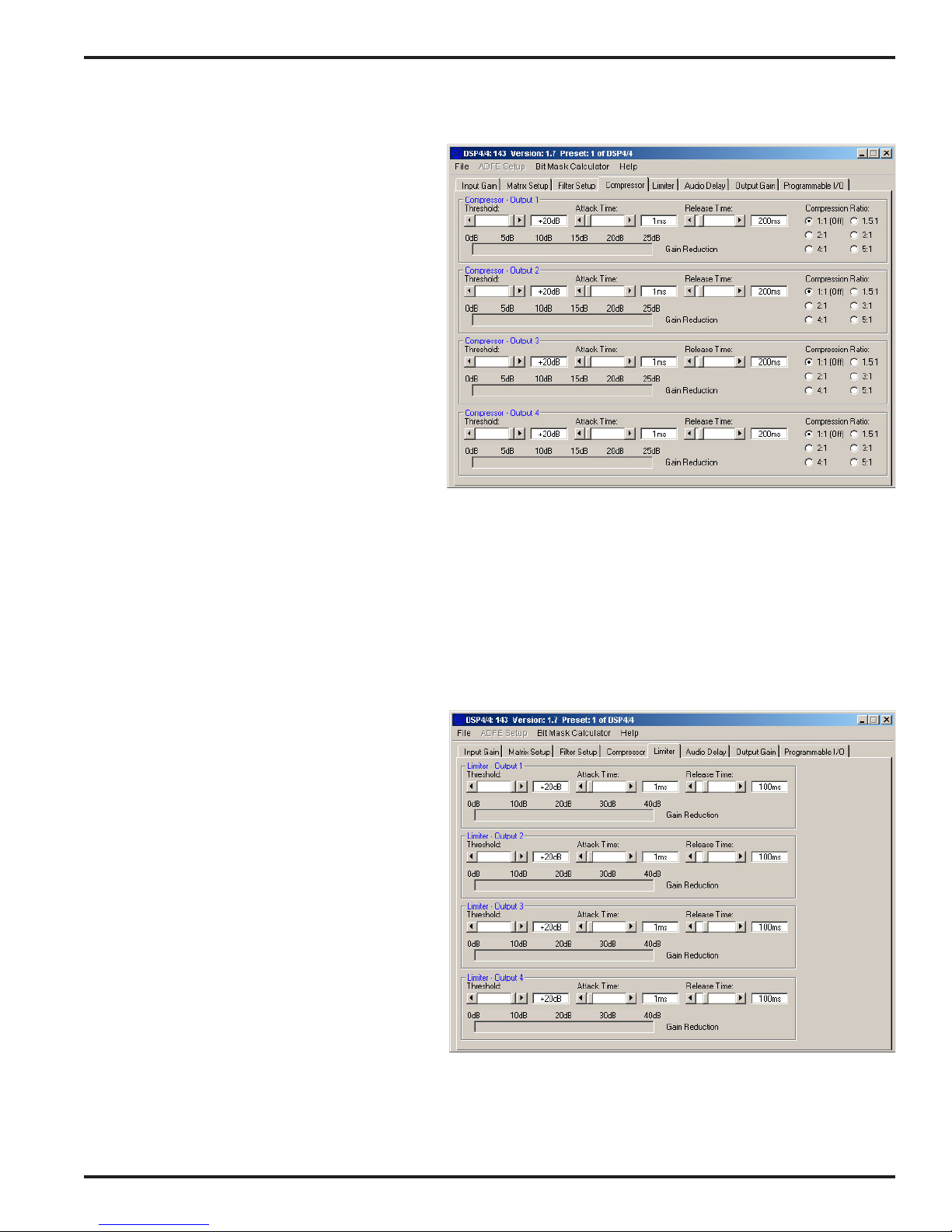
Compressor Tab
The Compressor Setup tab allows the setting of
the compressor parameters. These parameters
include attack time, release time, threshold, and
compression ratio. In addition, the gain reduction
introduced by the compressor is shown on the
gain reduction meter for each output.
Threshold - Sets the signal level at which
compression starts. Threshold range is adjustable from -40dBu to +20dBu, in 1dB steps.
Attack Time - Sets the attack time of the compressor. Attack times range from .5mS to
128mS, in .5mS steps.
Release Time - Sets the release time of the
compressor. Release times range from 10mS to
2.56S, in 10mS steps.
Compression Ratio - Sets the compression ratio
of the compressor. Compression ratios of 1:1 (i.e
no compression), 1.5:1, 2:1, 3:1, 4:1, 5:1 are
available. As the compression ratio is increased,
more gain reduction will be applied to any signal whose level is above threshold.
4 In / 4 Out Digital Audio Processor
Gain Reduction Meter - Shows the instantaneous amount of gain reduction being applied by the compressor to the
audio signal. Compressor gain reduction is limited to 25dB maximum, irrespective of the signal level and threshold.
Limiter Tab
The Limiter Setup tab allows the setting of the
limiterr parameters. These parameters include
attack time, release time, and threshold. The
compression ratio of the limiter is infinity:1
above threshold. In addition, the gain reduction
introduced by the limiter is shown on the gain
reduction meter for each output.
Threshold - Sets the signal level at which
limiting starts. Threshold range is adjustable
from -40dBu to +20dBu, in 1dB steps.
Attack Time - Sets the attack time of the limiter.
Attack times range from .125mS to 32mS, in
.125mS steps.
Release Time - Sets the release time of the
limiter. Release times range from 2mS to
512mS, in 2mS steps.
Gain Reduction Meter - Shows the instantaneous amount of gain reduction being applied
by the limiter to the audio signal. The limiter is
allowed to apply as much gain reduction as is necessary to keep the audio signal at or below threshold.
Rio Rancho, NM – USA
15
Page 16
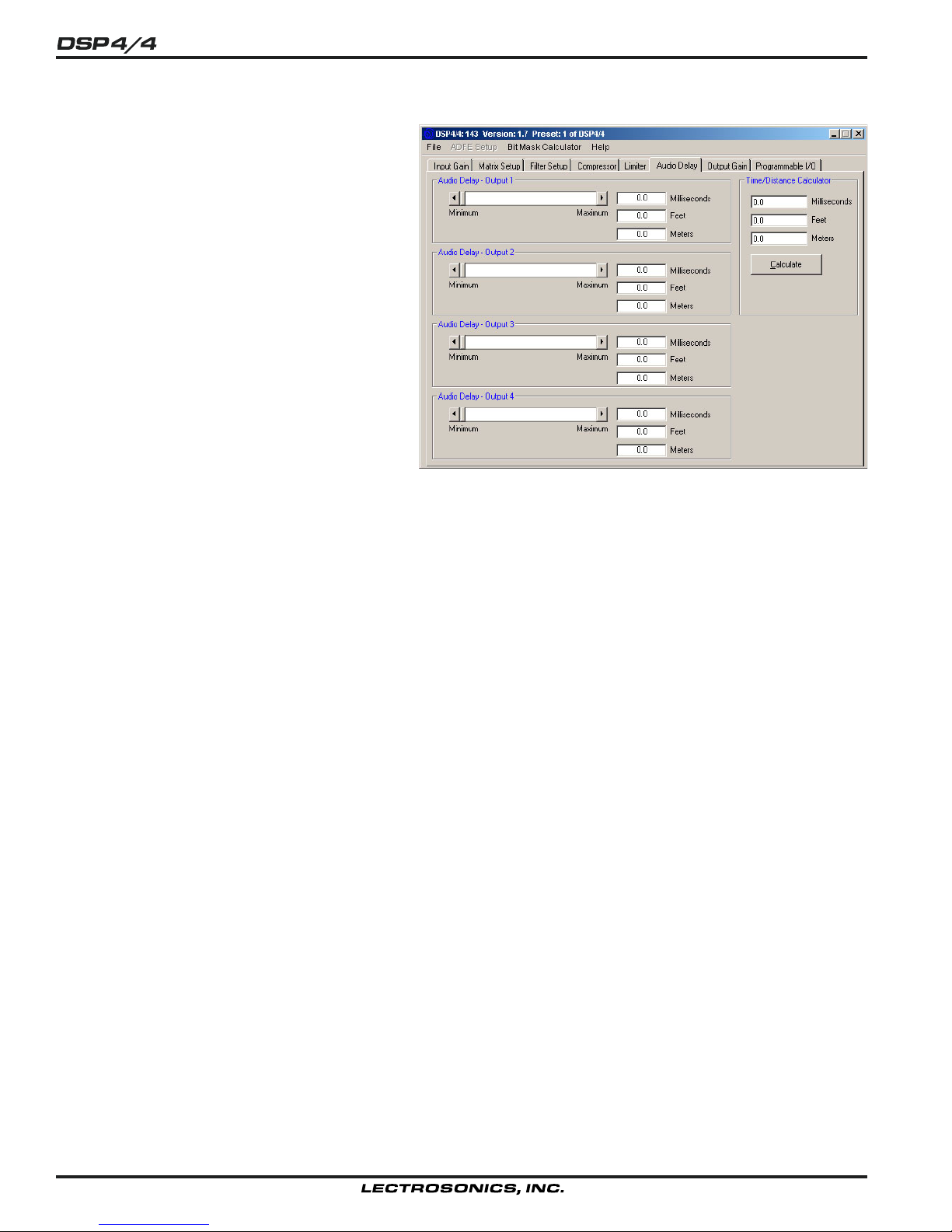
Audio Delay Setup Tab
The Audio Delay Setup tab allows the setting of
audio delay for each output channel. There is
also a distance/time calculator to make conversions between audio delay time and distance.
Audio Delay Scroll Bar - Allows the audio delay
to be set within the range of 0mS to 182.625mS.
Time increment size is 20.83uS. The equivalent
distance in both feet and meters is also given.
Time/Distance Calculator - Converts between
Milliseconds, Feet, and Meters. Fill in any one of
the text boxes and press the Calculate button.
16
Page 17
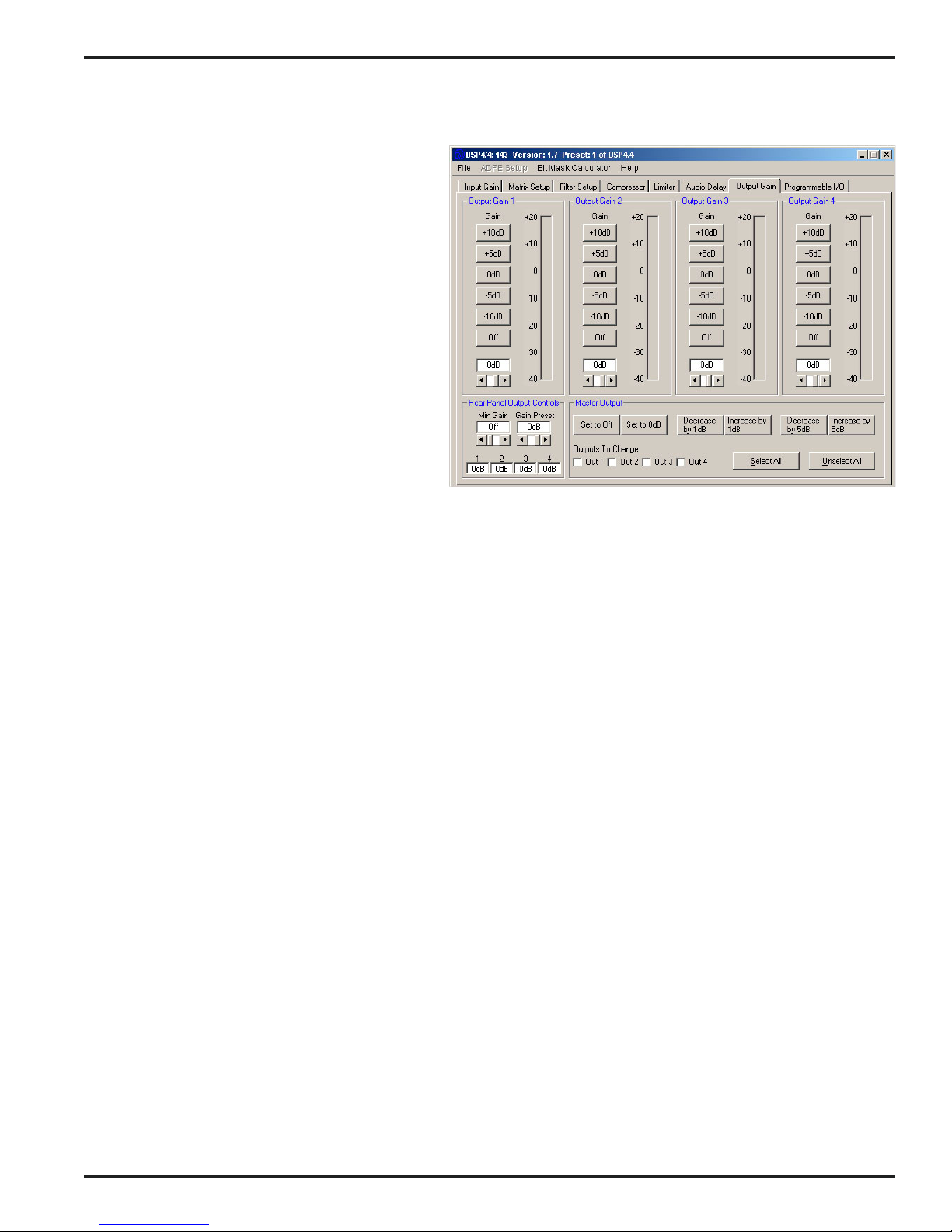
Output Gain Tab
The Output Gain tab allows the output gain levels
to be set.
Output Gain 1 - 4 - Allows the output gain to be
set between 0dB and -78dB or “Off”. In addition
to the gain scroll bar, 6 “quick gain set” buttons
will set the output gain to the indicated levels.
The background color of the output gain box will
change from white to red if the output is muted by
actuation of the Mute Output function of a programmable input. The output gain scroll bar and
the gain set buttons will also be disabled while
the output is muted.
4 In / 4 Out Digital Audio Processor
Short Cuts:
will set the output gain to 0dB, while a right
mouse click will set the output gain to Off.
Level Meter - Indicates the output level, taking
into consideration the Output Gain and rear panel
(i.e. programmable input) gain contributions.
Rear Panel Output Controls - Allows both a
preset level and limits to be placed on the gain range available for control of output gain using the programmable
inputs. The Gain Preset scroll bar sets the power-up attenuation applied to all outputs controlled by the Increment
Output 1dB or Decrement Output 1dB programmable input function. This attenuation will be added to the individual
output gains to derive the actual output gain value. The maximum adjustment range of the rear panel output control
goes from 0dB to -30dB (in 1dB steps) plus Off. The Min Gain scroll bar allows the gain adjustment range below 0dB
to be limited as needed for the application. “Off” signifies no lower gain limit. 0dB is the maximum value available for
Min Gain, and is equivalent to making rear panel output control inactive. The Min Gain value also applies to outputs
being controlled by the Analog Output Control programmable input. In this case, the Min Gain value represents the
attenuation applied when the pot connected to the programmable input is fully counter-clockwise (or a control voltage
applied to the programmable input is at 0VDC).
Short Cuts:
gain), while a right mouse click will set the minimum gain to 0dB.
The 4 boxes below the scroll bars show the current rear panel output gain setting for each output.
A left mouse click on the gain box
A left mouse click on the Min Gain box will set the minimum gain to Off (i.e. no limit on the minimum
Master Output Section
The Master Output section provides a convenient way to apply gain changes to more that one output at a time. The
six buttons (Set to Off, Set to 0dB, Decrease by 1dB, Increase by 1dB, Decrease by 5dB, and Increase by 5dB)
facilitate several common gain manipulations. Their action is applied to any output whose check box is checked. The
Select All and Unselect All buttons provide a quick way to apply gain changes to all channels simultaneously. Note
that the Increase and Decrease buttons are push-and-hold, and will increment or decrement the output gain for as
long as they are held down.
Rio Rancho, NM – USA
17
Page 18
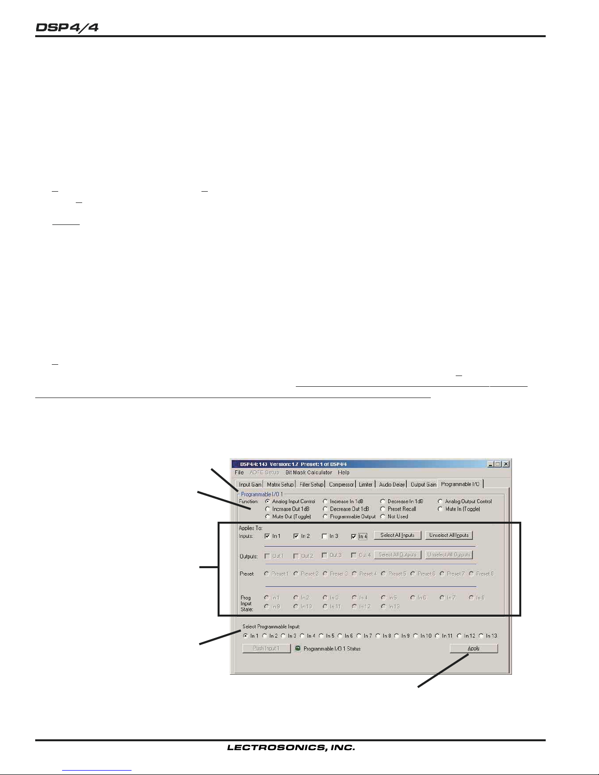
Programmable Input/Output Setup Tab
The DSP4/4 has 13 programmable pins on the 15 pin D-Sub connector on the rear panel which allow control and
indication of a wide variety of DSP4/4 functions. Pins 1-8 on the rear panel D-Sub connector can be programmed to
be either programmable inputs or programmable outputs, while pins 9-13 are only programmable inputs.
Only the parameters in the “Applies To” section which are associated with each specific programmable input/output
function will be enabled as you select different functions. All other parameters are disabled. This eliminates invalid
Function/Applies To settings. Each of the available functions is explained below.
Hint: If the function (or any associated inputs, outputs, etc.) of a programmable I/O is changed on the control panel,
the Apply button will be enabled. The Apply button is located in the lower right hand corner of the Programmable I/O
tab. The Apply button must be clicked before any changes are actually applied to the active DSP4/4 setup. Note that
you should use the Select Programmable Input Radio Buttons to select the programmable input you’d like to config-
ure
before doing any configuration.
Select Programmable Input Radio Buttons 1-13 - Allows selection of which programmable i/o to change. Note
that the frame caption “Programmable I/O ...” (upper left in blue) will change to indicate which programmable I/O is
currently being changed.
Push Input Button - Allows a contact closure to be simulated for the current programmable input. This is useful
when testing to see that the changes you’ve made to each programmable input indeed have the intended effect.
Each click on the “Push Input...” button has the same effect as a momentary contact closure on the current program-
mable input. Note that the caption on the Push Input button always reflects the current programmable input. The
Push Input button will be disabled for any programmable inputs which are “Not Used”, “Analog In” control, or “Analog
Out” control.
Apply Button - Applies the current setting of “Function” and “Applies To” to the current programmable input. When
the Apply button is enabled, this indicates that the setting of “Function” and “Applies To” in the DSP4/4 does not
match the setting of “Function” and “Applies To” shown on the control panel screen. Clicking the
load the control panel setting into the active DSP4/4 setup. This does not store the changes to a memory preset!
That must be done explicitly from the File/Save Active to DSP4/4 Preset... file menu option. If changes are made to
a programmable input but not applied (by clicking on the Apply button), and another programmable input is selected
(by clicking on of the Select Programmable Input buttons), all the changes to the first programmable input which
were not applied will be lost.
Apply button will
Active Programmable I/O indicated here
Select programmable function here
The “Applies To” section
Select programmable input here
18
The “Apply” button
Page 19

4 In / 4 Out Digital Audio Processor
Programmable I/O Status “LED” - Shows the current state of a programmable i/o. The status indicator only has
meaning for the following programmable input functions:
Analog In: LED ON - Analog In attenuation < 15dB
LED OFF - Analog In attenuation >= 15dB
Increase In 1dB: LED ON - Contact closure on prog input
LED OFF - No contact closure on prog input
Decrease In 1dB: LED ON - Contact closure on prog input
LED OFF - No contact closure on prog input
Analog Out: LED ON - Analog Out attenuation < 15dB
LED OFF - Analog Out attenuation >= 15dB
Increase Out 1dB: LED ON - Contact closure on prog input
LED OFF - No contact closure on prog input
Decrease Out 1dB: LED ON - Contact closure on prog input
LED OFF - No contact closure on prog input
Preset Recall: LED ON - Associated memory is active
LED OFF - Associated memory is not active
Mute In: LED ON - Associated input(s) not muted
LED OFF - Associated input(s) muted
Mute Out: LED ON - Associated output(s) not muted
LED OFF - Associated output(s) muted
Programmable Output: LED ON - Associated prog input is active
LED OFF - Associated prog input is not active
Rio Rancho, NM – USA
19
Page 20
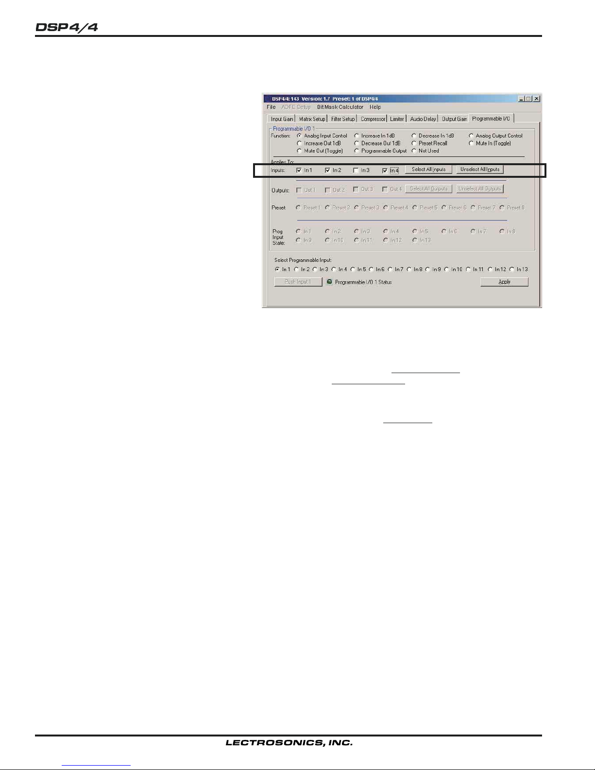
Controlling Audio Inputs
Analog Input Control - Allows one or more input
gains to be controlled by an analog voltage on a
programmable input pin. Analog input gain
control goes from a maximum of 0dB gain to a
minimum of 30dB attenuation, plus “Off”. The
gain change resolution is 1dB. The Analog Input
Control mode is ideal for using a pot (or some
other source of analog voltage) to control input
gain. The valid voltage range in the Analog Input
Control mode is 0VDC to 5VDC. 0VDC corresponds to “Off” (or Rear Panel Minimum Input
Gain, if it is programmed for less attenuation than
“Off”), and +5VDC corresponds to 0dB. In
addition to analog control, this mode can be used
to perform input “muting” using a simple toggle
switch. To mute input(s), simply connect the
toggle switch to connect the programmable input
to ground (GND pin). The screen shown here
indicates that the function of programmable I/O
number 1 is set to provide an analog input control
of inputs 1, 2, and 4. Notice how multiple inputs
may be controlled by a single programmable input.
Increase In 1dB / Decrease In 1dB - Allows one or more input gains to be controlled by a contact closure on a
programmable input pin. Increase and Decrease input gain control goes from a maximum of 0dB gain to a minimum
of 30dB attenuation, plus “Off”. The gain change resolution is 1dB. In the case of
closure will increment the input(s) gain by 1dB until 0dB is reached. Decrease In 1dB will decrement the input(s)
gains by 1dB until either “Off” or Rear Panel Minimum Input Gain is reached. If the contact closure is pushed and
held, it will continue to increment or decrement until it is released or the gain reaches its high or low limit.
Increase In 1dB, each contact
Mute In (Toggle) - Allows one or more inputs to be temporarily muted. The first momentary contact closure on the
programmable input pin will mute the specified input(s), and the next momentary contact closure will unmute them.
20
Page 21
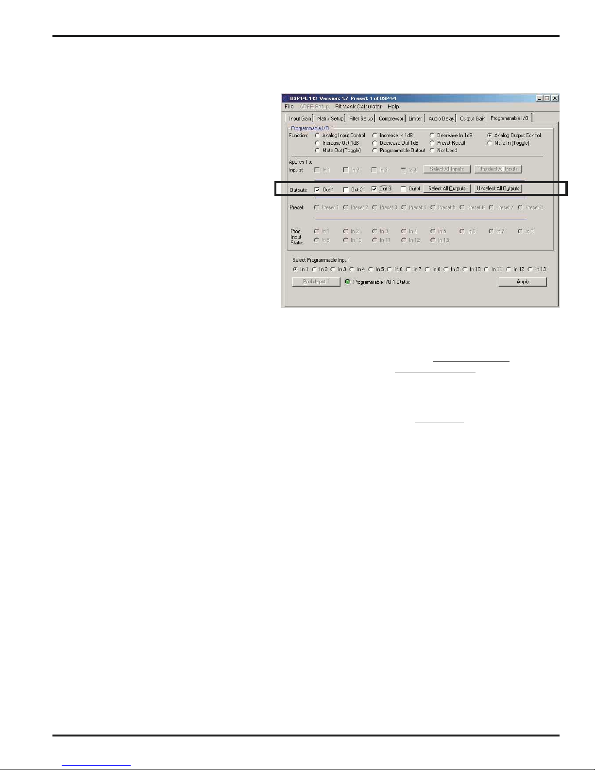
Controlling Audio Outputs
Analog Output Control - Allows one or more
output gains to be controlled by an analog voltage
on a programmable input pin. Analog output gain
control goes from a maximum of 0dB gain to a
minimum of 30dB attenuation, plus “Off”. The
gain change resolution is 1dB. The Analog
Output Control mode is ideal for using a pot (or
some other source of analog voltage) to control
output gain. The valid voltage range in the
Analog Output Control mode is 0VDC to 5VDC.
0VDC corresponds to “Off” (or Rear Panel
Minimum Output Gain, if it is programmed for less
attenuation than “Off”), and +5VDC corresponds
to 0dB. In addition to analog control, this mode
can be used to perform output “muting” using a
simple toggle switch. To mute output(s), simply
connect the toggle switch to connect the programmable input to ground (GND pin). The
screen shown here indicates that the function of
programmable input 1 is analog output control of
outputs 1 and 3 simultaneously.
4 In / 4 Out Digital Audio Processor
Increase Out 1dB / Decrease Out 1dB - Allows one or more output gains to be controlled by a contact closure on a
programmable input pin. Increase and Decrease output gain control goes from a maximum of 0dB gain to a minimum of 30dB attenuation, plus “Off”. The gain change resolution is 1dB. In the case of Increase Out 1dB, each
contact closure will increment the output(s) gains by 1dB until 0dB is reached.
Decrease Out 1dB will decrement the
output(s) gains by 1dB until either “Off” or Rear Panel Minimum Output Gain is reached. If the contact closure is
pushed and held, it will continue to increment or decrement until it is released or the gain reaches its high or low
limit.
Mute Out (Toggle) - Allows one or more outputs to be temporarily muted. The first momentary contact closure on
the programmable input pin will mute the specified output(s), and the next momentary contact closure will unmute
them.
Rio Rancho, NM – USA
21
Page 22
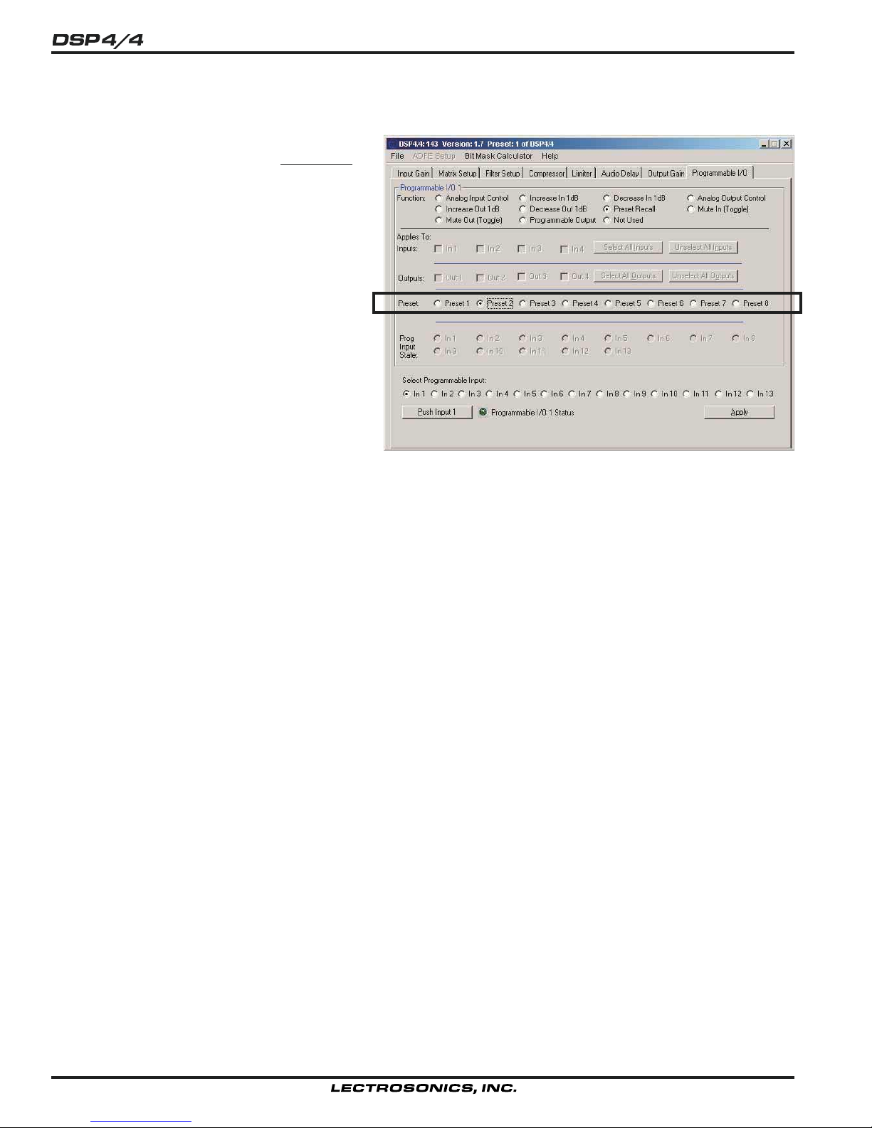
Recalling Memory Presets
Preset Recall - Allows one of the 8 DSP4/4
memory presets to be recalled by a momentary
contact closure on a programmable input pin. If
you are using two or more programmable inputs
for memory recall, you will want to set up and
apply all programmable input/memory preset
association and download the active setup to all
preset memories you’ll be using. This guarantees that the desired programmable input/
memory preset associations are stored in all
memories of interest. The screen shows that the
function of programmable I/O 1 is to recall
Memory Preset 2.
22
Page 23
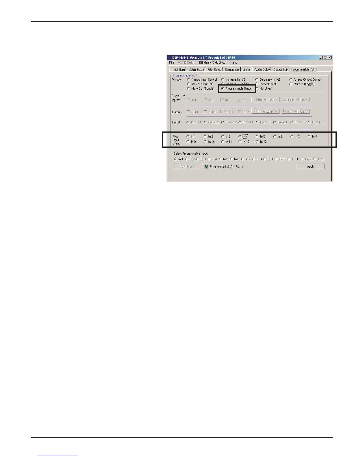
Programmable Output Functions
Programmable Output - Sets one of program-
mable I/Os on pins 1 through 8 to the Programmable Output mode. Programmable outputs are
used to trigger external devices such as LEDs to
indicate the state of an associated programmable
input. Since programmable I/Os can be configured for a variety of functions, the active/inactive
status of the programmable output will vary
accordingly.
A programmable output will be active (conducting
to ground) or inactive (open) as shown in the
table below relative to the state of the associated
programmable input. Refer to the section on
INSTALLATION on page 4 for the details on the
connection and use of programmable outputs.
The screen depicts a setup where programmable
I/O 1 (upper left part of screen) is configured to
indicate the status of programmable I/O 4 (highlighted group in lower part of screen). The
activity of I/O 1 will vary according to the function
and state of I/O 4.
4 In / 4 Out Digital Audio Processor
Prog. input function: Activity of Associated Programmable Output:
Analog In: Active - Analog In attenuation < 15dB
Inactive - Analog In attenuation >= 15dB
Increase In 1dB: Active - Contact closure on prog input
Inactive - No contact closure on prog input
Decrease In 1dB: Active - Contact closure on prog input
Inactive - No contact closure on prog input
Analog Out: Active - Analog Out attenuation < 15dB
Inactive - Analog Out attenuation >= 15dB
Increase Out 1dB: Active - Contact closure on prog input
Inactive - No contact closure on prog input
Decrease Out 1dB: Active - Contact closure on prog input
Inactive - No contact closure on prog input
Preset Recall: Active - Associated memory is active
Inactive - Associated memory is not active
Mute In: Active - Associated input(s) not muted
Inactive - Associated input(s) muted
Mute Out: Active - Associated output(s) not muted
Inactive - Associated output(s) muted
Programmable Output: Active - Associated prog input function active
Inactive - Associated prog input function inactive
Not Used - Unprograms a programmable i/o such that there will be no action associated with it.
Rio Rancho, NM – USA
23
Page 24

USING THE DSP4/4 TO IMPLEMENT AN ELECTRONIC CROSSOVER
The DSP4/4 can be used to implement multiway electronic crossovers using some of the user adjustable filters
available on each channel. The following note shows how to implement a stereo two-way crossover with 4th order
Linkwitz-Riley filters and a crossover frequency of 500Hz. The information presented can easily be extended to
implement mono two-way, three-way and four-way crossovers as well.
Stereo 2-Way Crossover Matrix Setup
The first step in designing an electronic crossover with the DSP4/4 is setting the input/output
matrix to get the desired signal flow. For a stereo
two-way crossover, inputs 1 and 2 will be used for
left and right inputs respectively. Outputs 1 and 2
will be used for left channel low and left channel
high, and outputs 3 and 4 will be used for right
channel low and right channel high. We’ll route
input one to outputs 1 and 2, and we’ll route input
2 to outputs 3 and 4. The Matrix Setup tab for
the stereo two-way crossover is shown here.
Stereo 2-Way Crossover Filter Setup
Now that the signal flow is established, step two
is to apply filtering to each path to get the low
frequency and high frequency portions of the
crossover. The Filter Setup tabs for outputs 1 and
2 (i.e. left channel low and left channel high) will
be shown. The right channel Filter Setup tabs are
identical except they use outputs 3 and 4.
Since a 4th order Linkwitz-Riley crossover is
simply a cascade of two 2nd order Butterworth
filters, each crossover output will use two of the
twelve user adjustable filter sections to implement
the crossover filtering function. The distinct
advantage of the Linkwitz-Riley alignment for
audio crossover filters is that the low pass and
high pass outputs sum to unity over the entire
frequency range. This implies that there are no
frequency response peaks or dips in the crossover region caused by the crossover itself.
The Filter Setup tab for the left channel low frequency output (output 1) is shown here.
Note that the first two user adjustable filters are both set to 12db/octave (i.e. 2nd order) low pass filters with a cut off
frequency of 500Hz. These two Butterworth filters in series produce the low pass section of the 4th order LinkwitzRiley crossover filter.
24
Page 25
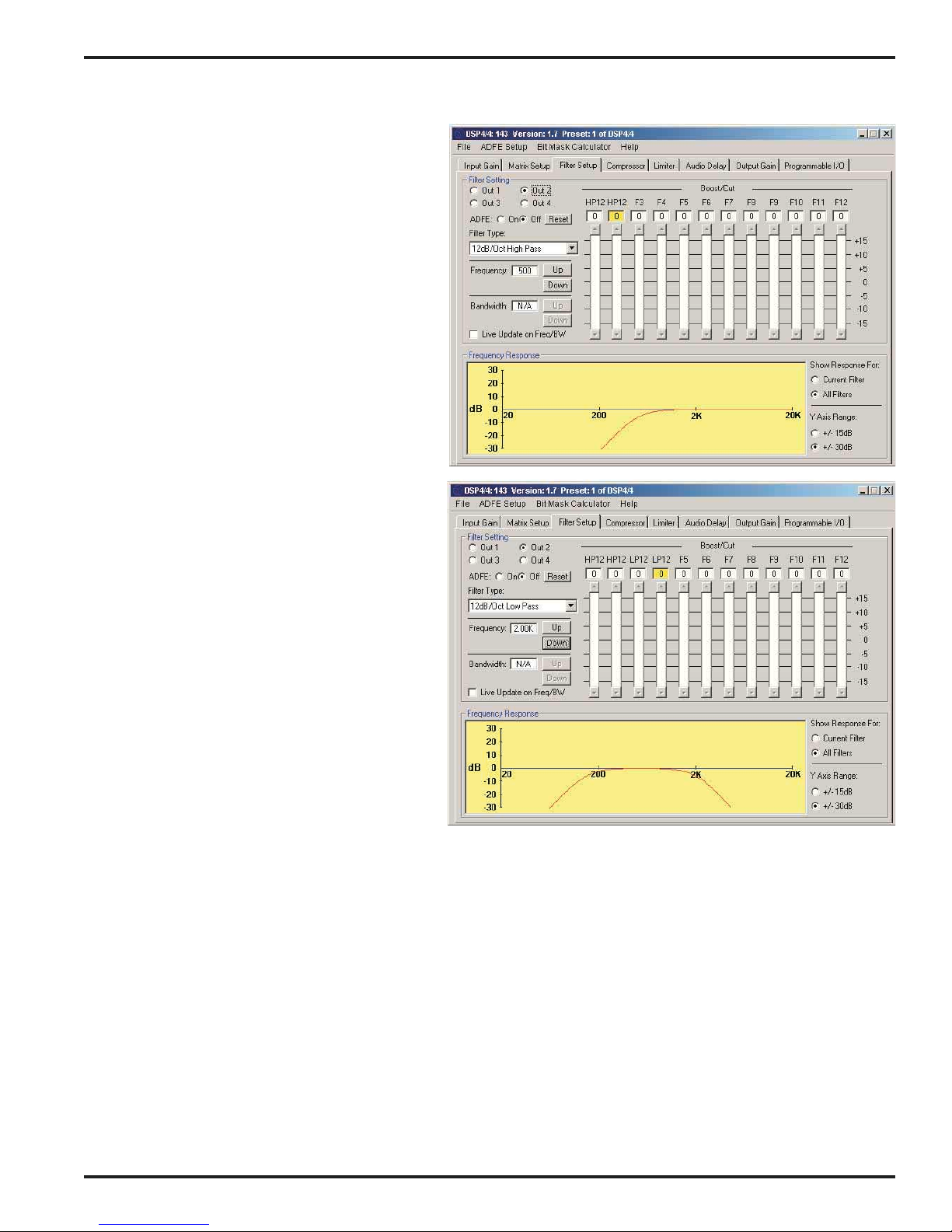
The Filter Setup tab for the left channel high
frequency output (output 2) is shown to the right.
Note that the first two user adjustable filters are
both set to 12db/octave (i.e. 2nd order) high pass
filters with a cut off frequency of 500Hz. These
two Butterworth filters in series produce the high
pass section of the 4th order Linkwitz-Riley
crossover filter.
For a mono three-way or four-way crossover, the
input/output matrix would be set to send one
input to three or four outputs, respectively. The
band pass sections of these crossovers would be
implemented using two LP12 user adjustable
filters for the high frequency corner and two
HP12 user adjustable filters for the low frequency
corner. An example filter setup is shown to the
right for a band pass section with a low frequency
corner of 150Hz and a high frequency corner of
2kHz.
4 In / 4 Out Digital Audio Processor
These steps are all that is necessary to implement the basic crossover. 10 user adjustable
filters (or 8 for the band pass sections of multiway crossovers) are still left for further driver
equalization and ADFE. Compression, limiting,
delay, and gain may also be applied to each
driver as necessary.
Rio Rancho, NM – USA
25
Page 26
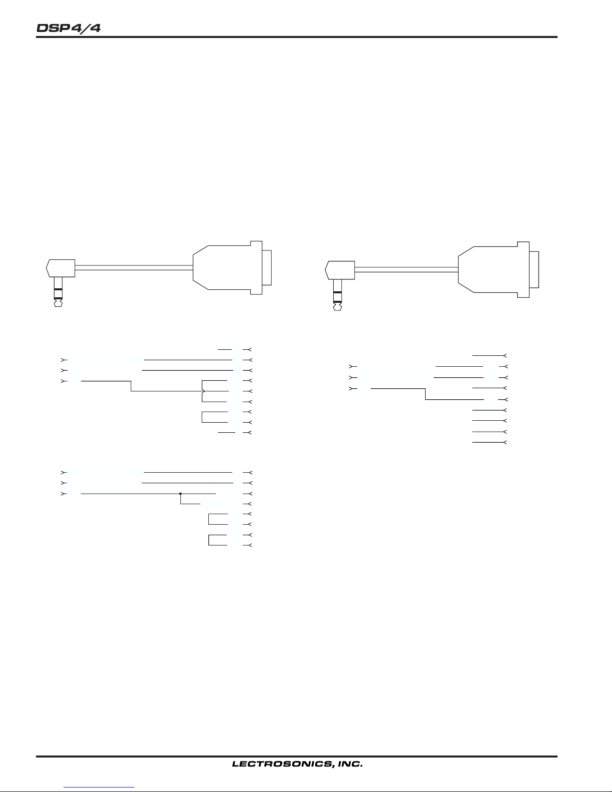
SERIAL CABLE WIRING DIAGRAM
The serial port on the DSP4/4 is a minimal RS-232 implementation. The figure shows the wiring diagram to
accommodate interconnection with either a 9 or a 25 pin serial port on a PC or other serial device.
AMX Programming Notes
If you are using an AMX system to control your LecNet equipment, you’ll want to purchase the Lectrosonics PT3
Protocol Translator. The PT3 connects between the AMX bus and any LecNet equipment. With the PT3, the LecNet
equipment looks just like native AMX equipment. The PT3 is the fastest and most productive way to control LecNet
devices with an AMX system.
S
R
T
Tip
Ring
Sleeve
Tip
Ring
Sleeve
LecNet Device to PC
3.5MM
Stereo Plug
Wiring Diagram, 9 Pin D-Sub
LecNet Device Transmit
LecNet Device Receive
Gnd
LecNet Port
Wiring Diagram, 25 Pin D-Sub
LecNet Device Transmit
LecNet Device Receive
Gnd
LecNet Port
9 or 25 Pin Female
D-Subminiature
CD
N/C
RX
TX
DTR
Gnd
DSR
RTS
CTS
N/C
Chassis Gnd
RI
RX
TX
Sig Gnd
RTS
CTS
DSR
DTR
20
1
2
3
4
5
6
7
8
9
3
2
7
1
4
5
6
Host
Serial
Port
(PC)
Host
Serial
Port
(PC)
S
R
T
Tip
Ring
Sleeve
LecNet Device to AMX or Crestron
3.5MM
Stereo Plug
LecNet Device Transmit
LecNet Device Receive
Gnd
LecNet Port
9 Pin Female
D-Subminiature
N/C
N/C
N/C
N/C
N/C
N/C
RXD
TXD
Gnd
1
2
3
AMX
4
or
5
Crestron
6
Port
7
8
9
26
Page 27

4 In / 4 Out Digital Audio Processor
SERIAL PORT COMMANDS AVAILABLE
The DSP4/4 uses a modification of the typical one-to-one connection between two RS-232 compatible devices. The
DSP4/4 has both an RS-232 transmitter and receiver section. The transmitter section is “tri-stated”, or placed in a
high impedance mode, until the particular device is addressed. To facilitate the simple parallel connection of multiple
devices on a single RS-232 port, an addressing scheme is employed to route commands from the host to the proper
device. When a device receives its address from the host computer, it temporarily turns on its RS-232 transmitter
long enough to send whatever data is requested by the host. In this way, multiple devices may drive a single transmit
signal back to the host, because only the addressed DSP4/4 will turn on its transmitter.
Valid address values are 128-254 (80h-FEh). The factory default address of the DSP4/4 is 143. 255 (FFh) is an
invalid address and must not be used. Because the DSP4/4 will interpret any single data byte whose value is greater
than 127 as an address, single byte data (as opposed to addresses) sent from the host must be in the range of 0-
127. If a data value needs to be output that exceeds 127, two bytes are output such that the first byte is the lower 7
bits of the 8 bit value, and the second byte is 1 if the MSB of the data byte is 1, or 0 if the MSB of the data byte is 0.
Every DSP4/4 command must be preceded by the address of the device to be controlled. If a device with the
requested address exists on the system, it will respond by sending a “0” back to the host. Each interchange with an
DSP4/4 follows this pattern:
1) Host sends device address (1 byte);
2) Host receives byte of “0” from DSP4/4 as acknowledgement;
3) Host sends command (1 byte) to DSP4/4;
4) Host and DSP4/4 interact based on particular command sent.
The following is a listing of available commands grouped based on the DSP4/4 function to which the commands are
related. The word “Host” in the command descriptions means the IBM PC, PC compatible, AMX Control System, or
Crestron Control System to which the DSP4/4 is connected.
General Device Commands
Get Name String - Gets the DSP4/4’s “name” string. The first data byte is the length of the name string, and the rest
of the data bytes are the device name.
Host sends command - 1 (1 hex)
Host receives 6 bytes: Byte 1 is the length of the name string (5 for the DSP44), bytes 2, 3, 4, 5 and 6 are
the ASCII values for “DSP44” (68, 83, 80, 52, 52).
Set Device Address - Sets the DSP4/4’s device address and stores the new address in nonvolatile memory. The
factory default address of the DSP4/4 is 143.
Host sends command - 2 (2 hex)
Host sends 1 byte: device address, valid range 128 to 254.
Get Firmware Version - Returns the version number of the DSP4/4’s current firmware. For example, Version 1.0
software would be returned as 10 (decimal).
Host sends command - 25 (19 hex)
Host receives 1 byte: firmware version.
Get DSP Software Version - Returns the version number of the DSP4/4’s current DSP software. For example,
Version 1.0 software would be returned as 10 (decimal).
Host sends command - 26 (1A hex)
Host receives 1 byte: firmware version.
Rio Rancho, NM – USA
27
Page 28

Memory Preset Commands
Get Current Memory Preset - Gets the currently active DSP4/4 memory preset value.
Host sends command - 21 (15 hex)
Host receives 1 byte: current memory preset, 0 - 7 representing memory presets 1 - 8.
Set Current Memory Preset - Sets the DSP4/4’s current memory preset. The DSP4/4 will immediately set all of its
programmable parameters to the new memory preset. The Mode data byte gives the option of memory
recall with or without affecting the current settings of the rear panel (i.e. programmable input controlled)
gains.
Host sends command - 22 (16 hex)
Host sends 2 byte:
Byte 1: New memory preset, 0 - 7 representing memory presets 1 - 8.
Byte 2: Mode, 0 resets the rear panel input and output gains to the programmed preset. 1 does not change
any of these gains.
Input Related Commands
Get Input Gain - Gets the input gain associated with any one input or all 4 inputs. This gain value is the same one
you can manipulate from the Input Gain tab on the DSP4/4 control panel.
Host sends command - 31 (1F hex)
Host sends 1 byte: input number to return, 0 - 3 returns the single gain value from inputs 1 - 4, while 4
returns 4 bytes representing the input gain of all inputs, starting with input 1.
Host receives 1 or 16 bytes: input gain(s), 0 - 79, where 0-78 represents +10dB to -68dB, and 79 is off. If
the input gain value is greater than 127, this means the input is muted. The unmuted gain may be derived by
subtracting 128 from the returned value.
Set Input Gain - Sets the input gain of 1 or more input channels.
Host sends command - 30 (1E hex)
Host sends 2 bytes:
Byte 1: A 4 bit mask, where each bit position represents one of the 4 inputs. For example, the lowest bit of
the mask represents input 1, the next lowest bit input 2, and so on. A “1” in a bit position will apply the gain
in byte 2 to the associated channel, while a “0” in a bit position will not apply the gain to the associated
channel.
Byte 2: Input gain value, 0 - 78, which represents +10dB to -68dB, 79 for off, 80 to increment the current gain
by 1dB, 81 to decrement the current gain by 1dB, 82 to mute the input, and 83 to unmute it to its pre-mute
gain value.
Output Related Commands
Get Output Gain - Gets the output gain associated with any one output or all 4 outputs. This gain value is the same
one you can manipulate from the Output Gain tab on the DSP4/4 control panel.
Host sends command - 61 (3D hex)
Host sends 1 byte: input number to return, 0 - 3 returns the single gain value from outputs 1 - 4, while 4
returns 4 bytes representing the output gain of all outputs, starting with output 1.
Host receives 1 or 12 bytes: input gain(s), 0 - 79, where 0-78 represents +10dB to -68dB, and 79 is off. If
the output gain value is greater than 127, this means the output is muted. The unmuted gain may be derived
by subtracting 128 from the returned value.
Set Output Gain - Sets the output gain of 1 or more input channels.
Host sends command - 60 (3C hex)
Host sends 2 bytes:
Byte 1: A 4 bit mask, where each bit position represents one of the 4 outputs. For example, the lowest bit of
the mask represents output 1, the next lowest bit output 2, and so on. A “1” in a bit position will apply the
gain in byte 2 to the associated channel, while a “0” in a bit position will not apply the gain to the associated
channel.
Byte 2: Input gain value, 0 - 78, which represents +10dB to -68dB, 79 for off, 80 to increment the current gain
by 1dB, 81 to decrement the current gain by 1dB, 82 to mute the input, and 83 to unmute it to its pre-mute
gain value.
28
Page 29

4 In / 4 Out Digital Audio Processor
Matrix Crosspoint Commands
Get Crosspoint Gain - Gets the gain associated with a particular matrix crosspoint.
Host sends command - 103 (67 hex)
Host sends 2 bytes:
Byte 1: Input associated with the desired crosspoint. 0 - 3, which corresponds to inputs 1 - 4.
Byte 2: Output associated with the desired crosspoint. 0 - 3, which corresponds to outputs 1 - 4.
Host receives 1 byte: Crosspoint gain. 0 - 31, where 0 - 30 represents +10dB to -20dB, and 31 is Off.
Set Crosspoint Gain - Sets the gain associated with a particular matrix crosspoint.
Host sends command - 102 (66 hex)
Host sends 3 bytes:
Byte 1: Input associated with the desired crosspoint. 0 - 3, which corresponds to inputs 1 - 4.
Byte 2: Output associated with the desired crosspoint. 0 - 3 corresponds to outputs 1 - 4.
Byte 3: Crosspoint gain. 0 - 31, where 0 - 30 represents +10dB to -20dB, and 31 is Off.
Programmable I/O Commands
Simulate a Programmable Input Button Push - Allows a function associated with a specific programmable input to
be triggered just as if a contact closure on that programmable input had taken place. This command is
particularly useful when using AMX or Crestron control systems, because very complex DSP4/4 actions may
be triggered by one serial command. The programmable input must first be programmed with the desired
function using the Programmable Inputs tab on the DSP4/4 control panel before this command is used.
Host sends command - 122 (7A hex)
Host sends 1 byte: Programmable input to trigger, 1 - 13
Host receives 1 byte: 0D (hex) to acknowledge the simulated push
Get Programmable I/O Current State - Gets the current state of one of the 13 programmable inputs or 8 program-
mable outputs. Returns a 1 or a 2, where 2 means the programmable i/o is active, and 1 means it is inactive.
Host sends command - 123 (7B hex)
Host sends 1 byte: Programmable output whose state to return, 1 - 13.
Host receives 1 byte: Programmable output state, 1 or 2. 2 is active, 1 is inactive.
Rear Panel Attenuator Commands
Set Rear Panel Input Gain - Sets the rear panel attenuator
Host sends command - 124 (7C hex)
Host sends 2 bytes:
Byte 1: A 4-bit mask [...] (copy from “Set Input Gain”)
Byte 2: Attenuator setting 0-31, where 0 represents fully-off (muted) and the range 1-31 represents 1 dB
steps from -30 dB to to + 0 dB. This byte can also be 80, to increment 1 dB, or 81, to decrement 1 dB. Note
that the special mute and unmute commands (82 and 83), available with the “Set Input Gain” command, are
not supported for the rear panel attenuator.
Set Rear Panel Output Gain - Sets the rear panel attenuator
Host sends command - 125 (7D hex)
Host sends 2 bytes:
Byte 1: A 4-bit mask [...] (copy from “Set Output Gain”)
Byte 2: Attenuator setting 0-31, where 0 represents fully-off (muted) and the range 1-31 represents 1 dB
steps from -30 dB to to + 0 dB. This byte can also be 80, to increment 1 dB, or 81, to decrement 1 dB. Note
that the special mute and unmute commands (82 and 83), available with the “Set Output Gain” command,
are not supported for the rear panel attenuator.
Rio Rancho, NM – USA
29
Page 30

TROUBLESHOOTING
The DSP4/4 is so easy to use that you’ll probably never have any trouble with it. In the unlikely event that you might,
here are a few tips for diagnosing problems:
1) If you get no sound (and the DSP4/4 power is on), first check the Input Gain tab. If the number in the Gain box is
too low, you might want to turn it up a bit. If the Gain box has a red background, it means the input has been
muted. This is only possible from the programmable inputs. If you have any programmable inputs assigned
(accidentally or on purpose) to the Mute In function, now is a good time to check the state of those programmable
inputs using the Programmable Inputs tab. If the rear panel controls for the input are set to off, you’ll get no
sound. The current gain value associated with these controls can be monitored using the Input Gain tab. If all is
well with all the input gain adjusting points, you should see some activity on the input level meter when signal is
present on an input.
2) So, you have input signal and the meter is dancing, but you still don’t have any sound. Check the Matrix Setup
tab to be sure that the input is actually assigned to the desired output(s).
3) The matrix is just where it ought to be, but by golly, you still don’t hear anything. Look at the Output Gain tab.
Again, if the Gain box has a red background, it means the output has been muted. This is only possible from the
programmable inputs. If you have any programmable inputs assigned (accidentally or on purpose) to the Mute
Out function, check the state of those programmable inputs using the Programmable Inputs tab. If the rear panel
controls for the output are set to off, you’ll get no sound. The current gain value associated with these controls
can be monitored using the Output Gain tab.
4) If you still don’t have any sound by now, you should sweat a few bullets and check out your microphone wiring,
the wiring from your mixer to the DSP4/4, and the wiring from your DSP4/4 to the power amp. Also check to see
that the power is on to all the other equipment in the rack. If everything seems to be as it should be but still no
sound, give us a call at 1-800-821-1121 or 505-892-4501 between 8am and 5pm Mountain Time. We’ll be happy
to help you troubleshoot.
30
Page 31

SPECIFICATIONS
4 In / 4 Out Digital Audio Processor
Connectors
Audio: 5-pin Phoenix style
Exp In/Out: 8-pin mini DIN
Programmable I/O: 15 pin D-Sub
LecNet RS-232: 3.5mm Stereo jack
Audio Inputs
Line Input Type: Electronically Balanced and RF Filtered
Input Impedance: >40k Ohms, Balanced/Unbalanced
Maximum Input Level: +20dBu
Gain Range: +10dB to -68dB, plus off
Outputs
Line Output Type: Electronically Balanced and RF filtered
Output Impedance: 200 ohms balanced, 100 ohms unbalanced
Output Gain Range: 0dB to –78dB, 1dB steps, plus mute
Maximum Output Level: +20dBu
Matrix Crosspoints
Matrix Crosspoint
Gain Settings: +10dB to -20dB, plus off in 1dB steps
User Defined Filters
Types Available: 1st order highpass and lowpass
2nd order highpass, bandpass, and lowpass
1st order shelving bass and treble
2nd order shelving bass and treble
Parametric
Feedback Eliminator (ADFE)
Filter Type: 1/5 octave notch, placed with 1/10
octave accuracy
Filter Cut: -6dB, -12dB
Filter Range: 100Hz to 5.6kHz
Compressor
Attack Time: 0.5mS to 128mS in 0.5mS steps
Release Time: 10mS to 2.55S in 10mS steps
Threshold: +20dBu to -40dBu in 1dB steps
Compression Ratio: 1:1, 1.5:1, 2:1, 3:1, 4:1, 5:1
Limiter
Attack Time: 0.125mS to 32mS in 0.125mS steps
Release Time: 2mS to 512mS in 2mS steps
Threshold: +20dBu to -40dBu in 1dB steps
Digital Delay
Delay Time: 182.625mS maximum, in 20.83uS steps
Programmable Inputs/Outputs
Programmable Input Range: 0VDC - 5VDC
Analog Control: 0dB to -30dB plus of f control range
156mV/dB control sensitivity
Logic Control: Active Low
Programmable Output: Active low
Max sink current: 100 mA
Max supply voltage: 40VDC
Serial Communication
Default LecNet Address: DSP4/4: 143; DSP4/4 Dual: 143, 144
Serial Comm Parameters: RS-232, 9600 baud, 8 data bits, no parity,
1 stop bit
System:
Overall Latency: 3 ms
System THD: Less than 0.05%, +20dBu in, +20dBu out
System IMD: Less than 0.05%
Power Consumption: DSP4/4: 10 Watts max at 16.5VAC;
Dual: 20 Watts max at 16.5VAC
Weight: 3.5 lbs. (4 lbs for dual)
Dimensions: 19" wide x 1.75" high x 8" deep
This equipment has been tested and found to comply with the limits for a class B digital device, pursuant
to Part 15 of the FCC Rules. These limits are designed to provide reasonable protection against harmful
interference in a residential installation. This equipment generates, uses and can radiate radio frequency
energy and, if not installed and used in accordance with the instructions, may cause harmful interference
to radio communications. If this equipment does cause harmful interference to radio or television reception, which can be determined by turning the equipment off and on, the user is encouraged to try to
correct the interference by one or more of the following measures:
• Reorient or relocate the receiving antenna.
• Increase the separation between the equipment and receiver.
• Connect the equipment into an outlet on a circuit different from that to which the receiver is connected.
• Consult the dealer or an experienced radio/TV technician for help.
FCC PART 15 NOTICE
Rio Rancho, NM – USA
31
Page 32
SERVICE AND REPAIR
If your system malfunctions, you should attempt to correct or isolate the trouble before concluding that the equipment
needs repair. Make sure you have followed the setup procedure and operating instructions. Check out the interconnecting cords and then go through the TROUBLE SHOOTING section in the manual
We strongly recommend that you do not try to repair the equipment yourself and do not have the local repair shop
attempt anything other than the simplest repair. If the repair is more complicated than a broken wire or loose connection, send the unit to the factory for repair and service. Don’t attempt to adjust any controls inside the units.
Once set at the factory, the various controls and trimmers do not drift with age or vibration and never require readjustment. There are no adjustments inside that will make a malfunctioning unit start working.
LECTROSONICS’ service department is equipped and staffed to quickly repair your equipment. In warranty repairs
are made at no charge in accordance with the terms of the warranty. Out of warranty repairs are charged at a
modest flat rate plus parts and shipping. Since it takes almost as much time and effort to determine what is wrong
as it does to make the repair, there is a charge for an exact quotation. We will be happy to quote approximate
charges by phone for out of warranty repairs.
RETURNING UNITS FOR REPAIR
You will save yourself time and trouble if you will follow the steps below:
A. DO NOT return equipment to the factory for repair without first contacting us by letter or by phone. We need to
know the nature of the problem, the model number and the serial number of the equipment. We also need a phone
number where you can be reached 8 am to 4 pm (Mountain Standard Time).
B. After receiving your request, we will issue you a return authorization number (R.A.). This number will help speed
your repair through our receiving and repair departments. The return authorization number must be clearly shown
on the outside of the shipping container.
C. Pack the equipment carefully and ship to us, shipping costs prepaid. If necessary, we can provide you with the
proper packing materials. UPS is usually the best way to ship the units. Heavy units should be “double-boxed” for
safe transport.
D. We also strongly recommend that you insure the equipment, since we cannot be responsible for loss of or damage
to equipment that you ship. Of course, we insure the equipment when we ship it back to you.
Mailing address: Shipping address: Telephones:
Lectrosonics, Inc. Lectrosonics, Inc. Regular: (505) 892-4501
PO Box 15900 581 Laser Rd. Toll Free (800) 821-1121
Rio Rancho, NM 87174 Rio Rancho, NM 87124 FAX: (505) 892-6243
USA USA
We b: http://www.lectrosonics.com Email: sales@lectrosonics.com
32
Page 33

4 In / 4 Out Digital Audio Processor
This product meets the CE Compliance Standards - EN55022 and
EN50082-1:1998. A copy of the Declaration of Conformity may be
requested from your dealer or by contacting the factory directly:
Lectrosonics, Inc.
Marketing Department
581 Laser Rd. NE, Rio Rancho, NM 87124 USA
tel: 505-892-4501 fax: 505-892-6243 e-mail: marketing@lectrosonics.com
Rio Rancho, NM – USA
33
Page 34

LIMITED ONE YEAR WARRANTY
LIMITED ONE YEAR WARRANTY
The equipment is warranted for one year from date of purchase against defects in
materials or workmanship provided it was purchased from an authorized dealer. This
warranty does not cover equipment which has been abused or damaged by careless
handling or shipping. This warranty does not apply to used or demonstrator equipment.
Should any defect develop, Lectrosonics, Inc. will, at our option, repair or replace any
defective parts without charge for either parts or labor. If Lectrosonics, Inc. cannot
correct the defect in your equipment, it will be replaced at no charge with a similar new
item. Lectrosonics, Inc. will pay for the cost of returning your equipment to you.
This warranty applies only to items returned to Lectrosonics, Inc. or an authorized
dealer, shipping costs prepaid, within one year from the date of purchase.
This Limited Warranty is governed by the laws of the State of New Mexico. It states the
entire liablility of Lectrosonics Inc. and the entire remedy of the purchaser for any
breach of warranty as outlined above. NEITHER LECTROSONICS, INC. NOR
ANYONE INVOLVED IN THE PRODUCTION OR DELIVERY OF THE EQUIPMENT
SHALL BE LIABLE FOR ANY INDIRECT, SPECIAL, PUNITIVE, CONSEQUENTIAL,
OR INCIDENTAL DAMAGES ARISING OUT OF THE USE OR INABILITY TO USE
THIS EQUIPMENT EVEN IF LECTROSONICS, INC. HAS BEEN ADVISED OF THE
POSSIBILITY OF SUCH DAMAGES. IN NO EVENT SHALL THE LIABILITY OF
LECTROSONICS, INC. EXCEED THE PURCHASE PRICE OF ANY DEFECTIVE
EQUIPMENT.
This warranty gives you specific legal rights. You may have additional legal rights which
vary from state to state.
LECTROSONICS, INC.
581 LASER ROAD
RIO RANCHO, NM 87124 USA
www.lectrosonics.com
January 2, 2003
 Loading...