

Page 1

DR185
RATIO DIVERSITY RECEIVER
OPERATING INSTRUCTIONS
and trouble-shooting guide
LECTROSONICS, INC.
Rio Rancho, NM
Page 2

INTRODUCTION
Thank you for selecting the Lectrosonics system.
The DR185 represents over 70 years of combined experience in the design of RF
and audio devices and sets new standards for RF performance and flexibility. This
receiver utilizes a “maximal ratio combining” technique, providing a very effective
type of diversity reception. This is the first high performance receiver on the market
to utilize this technique to combine the outputs of two separate receivers without
hard-switching. The result is seamless audio reproduction without dropouts and
superb, noise-free operation, even in weak overall signal conditions.
This is a “true diversity” receiver in the purest sense. The audio outputs of two
separate receivers are mixed via a non-switching circuit that blends the two audio
signals together in an optimum ratio. The ratio of this mixture is controlled by a
circuit that monitors the comparative signal to noise ratios in both receivers and then
“pans” back and forth to regulate the mixture. The receiver with the least high
frequency noise is favored in the resultant blend.
The DR185 receiver was designed for professional users who demand outstanding
performance and flexibility. It is compatible with all Lectrosonics high band
transmitters.
TABLE OF CONTENTS
INTRODUCTION ................................................................................................... 2
GENERAL TECHNICAL DESCRIPTION ............................................................. 3
FRONT PANEL CONTROLS AND FUNCTIONS ................................................. 4
REAR PANEL CONTROLS AND FUNCTIONS ................................................... 5
ANTENNA USE AND PLACEMENT .................................................................... 6
OPERATING INSTRUCTIONS ............................................................................. 7
INDICATOR QUICK REFERENCE ....................................................................... 7
TROUBLESHOOTING ........................................................................................... 8
REPLACEMENT PARTS and ACCESSORIES.................................................... 8
SPECIFICATIONS AND FEATURES.................................................................... 9
SERVICE AND REPAIR ...................................................................................... 10
RETURNING UNITS FOR REPAIR .................................................................... 10
WARRANTY ........................................................................................... Back cover
2
Page 3
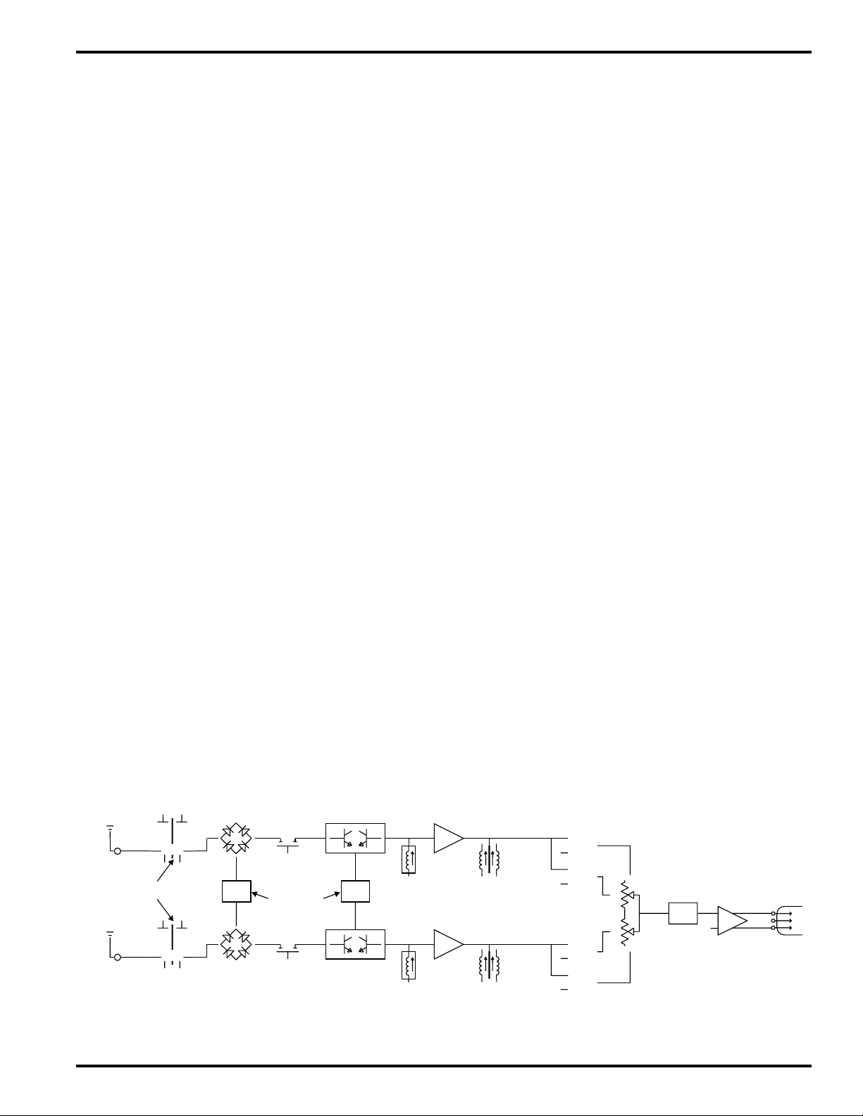
GENERAL TECHNICAL DESCRIPTION
Ratio Diversity Receiver
The DR185 receiver consists of two independent receivers operating with common first and second oscillators. The
audio outputs of the two receivers are mixed via a comparator circuit in a ratio controlled by sampling and comparing
the signal to noise ratios in both receivers. High frequency noise is compared between the receivers and an electronic “panning” circuit mixes in a greater percentage of audio from the quieter receiver. The panning action is
damped to prevent ill effects caused by transients in the signal. The purpose of this approach is to utilize the maximum amount of useable audio from both receivers simultaneously. By sampling and mixing the audio rather than
using RF level as reference, several major benefits are enjoyed, including:
a) The diversity action occurs irrespective of RF level.
b) No audible effects of “hard-switching” are produced.
c) A 3dB improvement in signal/noise ratio occurs with a strong RF signal at both receivers.
Each receiver is comprised of five functional subsystems: the RF front-end, the double balanced mixer/local oscillator,
the first IF filter, the second IF filter and audio demodulator and the compandor. The receivers share a common
comparator circuit and audio section.
The RF front-end consists of three cascaded pairs of helical resonators for high selectivity. Between the first and
second pair, and the second and third pair of helical resonators are low noise, grounded gate J-FET amplifiers.
These amplifiers are designed to provide only enough gain to make up for the loss through the helical resonators.
This combination of low front-end gain, coupled with the extremely high selectivity of the helical resonators prevents
overload in the mixer and provides exceptionally high image rejection, even with extremely strong RF signals. Rejection of out-of-band signals is maximized, and intermodulation products are suppressed.
The first mixer stage consists of a high level, double balanced diode mixer. The oscillator is biased from a regulated
supply, yielding stable performance. The local oscillator crystal operates at approximately 16MHz, and can be
adjusted above and below the nominal frequency in order to place the 21.4mHz IF in the center of the crystal filter’s
narrow passband. The high selectivity of the crystal filter stage further minimizes the possibility of interference from
signals on adjacent frequencies.
The second IF filter and the audio demodulator, as well as the squelch and RF LED drive are provided by one monolithic integrated circuit. The second IF filter is centered on 1MHz, and drives a double tuned quadrature type FM
demodulator. The squelch circuit is a supersonic noise detector type and is factory set for a -20dB SINAD level
(about .5uV). The squelch level is regulated and temperature compensated to maintain a consistent squelch level
under all conditions.
The compandor is driven by a multiple pole active low-pass filter. This filter ensures that supersonic noise will not
cause the compandor to increase gain incorrectly. The compandor senses the signal level, and dynamically increases the gain for loud signals or decreases the gain for soft signals. In this way, the original dynamic range of the
transmitted signal is restored, while preserving a high signal-to-noise ratio. The expansion ratio is 2:1, which produces a 2dB change in output level for a 1dB change in input level. In addition, the compandor has a de-emphasis
network that is complementary to the pre-emphasis network in the transmitter.
ANT
RECEIVER "A"
6 SECTION
HELICAL RESONATOR
ANT
RECEIVER "B"
DOUBLE BALANCED
DIODE MIXER
1st
CRYSTAL FILTER
OSCILLATORS
6 POLE HIGH
FREQUENCY
DOUBLE BALANCED
ACTIVE MIXER
2nd
LC FILTER
IF AMP
DOUBLE TUNED
DISCRIMINATOR
ACTIVE FILTERS
SEPARATING
NOISE AND AUDIO
N
A
N
A
COMPLIMENTARY
EXPANDER
OPTICALLY COUPLED
PANNING CIRCUIT
BALANCED
OUTPUT STAGE
DR185 Block Diagram
Rio Rancho, NM – USA
3
Page 4
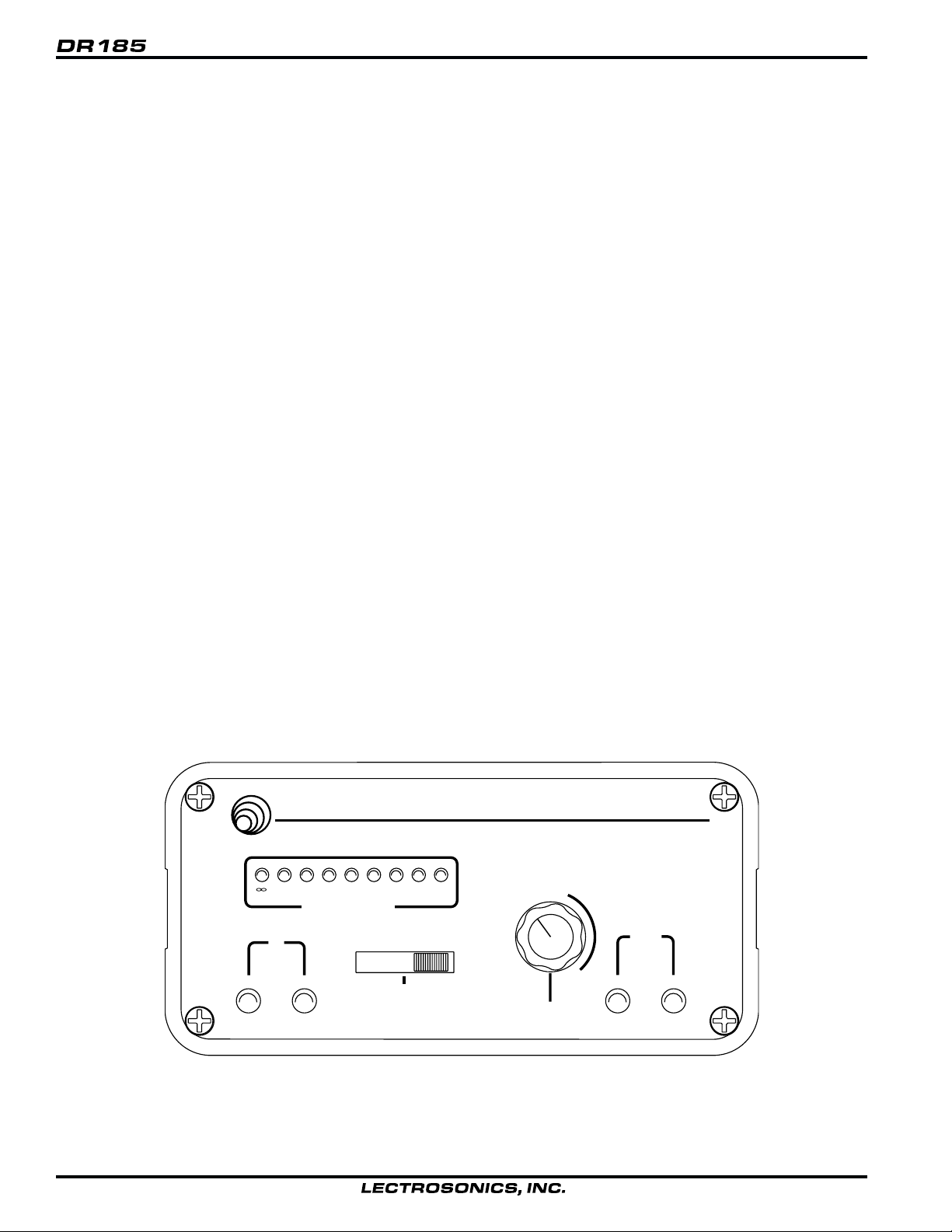
FRONT PANEL CONTROLS AND FUNCTIONS
MODULATION INDICATORS
Nine (9) LEDs indicate the audio level (modulation) of the incoming signal, which are typically used for proper adjustment of the transmitter’s “MIC LEVEL” or “GAIN”. The leftmost LED (red) functions as a pilot lamp to indicate that the
receiver is powered up. The seven green LEDs indicate the modulation level of the signal. The rightmost yellow LED
indicates maximum modulation and that the transmitter audio input may be “limiting.”
OFF/MUTE/ON
This switch turns the receiver power off and on and selects either an “audio mute” or “audio on” operation. The “audio
mute” position is normally used to cut the audio output from the receiver while observing the modulation LEDs to
adjust the transmitter gain.
RF INDICATOR
Two LEDs are provided to indicate the status of each receiver in the DR185. These LEDs glow when the transmitter
is turned on and the receiver has a good RF signal. When the carrier signal from the transmitter is too weak to
produce a clean audio signal, the lamp will go out.
OPTI-BLEND LEDs
The audio outputs of two separate receivers are mixed together in a “ratio” that is regulated by comparing the signal
to noise ratios in the two receivers. The mixture ratio of the two audio signals is indicated on the front panel by two
LEDs that vary in brightness. As a build-up of noise occurs in one receiver, the corresponding LED for that receiver
dims or goes out as the circuitry pans to the other receiver. Since the mixture ratio of the two audio signals is determined by a comparison of their signal to noise ratios, the “blending” action occurs regardless of how strong (or weak)
the incoming RF signals are. This is the distinct advantage of this receiver design over any other type of diversity
system available.
OUTPUT ATTENUATOR
This control knob adjusts the output levels of the two balanced outputs on the rear panel (XLR and 1/4"). In a fully
clock-wise position, the output at the XLR jack will be 100mV when the signal is a full modulation. The “-3,” “-12dB”
and “-20” markings indicate the knob position that will lower the audio output by the “dB” amount on the markings
around the knob.
LECTROSONICS
DIVERSITY RECEIVER
DR185
-24 -20 -15 -12 -7 -3 0 +3
dB AUDIO LEVEL
RF
A B
OFF ON
AUDIO
MUTE
POWER
-12dB
-20
-50
0dB
OUTPUT
ATTENUATOR
N
-3
O
R
M
A
L
OPTI
BLEND
A B
DR185 Front Panel
4
Page 5

Ratio Diversity Receiver
REAR PANEL CONTROLS AND FUNCTIONS
ANTENNA INPUTS
hese inputs connect to any 50 ohm antenna with a BNC type connector.
12 VDC INPUT
This input connects to the supplied CH-12 AC adapter for powering the receiver from a 110/120V AC source. The
receiver may also be powered from external 12 volt DC sources using the correct plug (Switchcraft S-760 power
plug). The center pin is positive. (+).
AUDIO OUTPUTS
XLR: This XLR type connector supplies a balanced, low impedance output at microphone level. The audio signal
is present on pins 2 and 3, while pin 1 is ground. The output level of this jack is controlled by the OUTPUT
ATTENUATOR control on the front panel of the receiver. Pin 2 is “hot” in terms of polarity.
1/4": A high level (700mV max.) output at medium impedance (600 ohms). This is a three conductor jack with
the tip and ring carrying the signal and the sleeve as shield. The tip is “hot” in terms of polarity. Output from this
jack is controlled by the OUTPUT ATTENUATOR control on the front panel.
RCA: A 1 Volt “line” output at 1K Ohms. The output of this jack is not controlled by the OUTPUT ATTENUATOR
control on the front panel.
AUDIO IN: This is an audio input providing a unity gain mixing bus input via a standard RCA jack. Signal applied
to this jack will appear at all three output jacks. This input is provided as a convenience in multiple channel
installations with simple mixing requirements, or for patching in another audio source (tape deck, etc.). Multiple
DR185 receivers may be “stacked” with mixed audio output by connecting the LINE OUT jack of one receiver to
the AUDIO IN of the next receiver, and so on. Up to four or five receivers may be “stacked” in this manner before
noise build-up becomes objectionable.
ANTENNAS
B A
12V DC INPUT
BAL 600
700 mV MAX
LINE OUT
AUDIO OUTPUTS
BAL MIC LEVEL
100 mV MAX
LINE IN
LECTROSONICS
RIO RANCHO, NM MADE IN USA
DR185 Rear Panel
Rio Rancho, NM – USA
5
Page 6

ANTENNA USE AND PLACEMENT
There are two antennas included with this receiver. One is a telescoping whip that connects to either terminal on the
rear panel of the DR185 receiver. The other antenna is a coaxial type for use away from the receiver. This remote
coaxial antenna should be positioned so that the stripped end of the coaxial cable is at least 4 or 5 feet (1/2 wavelength or more) away from the whip antenna. This will insure the maximum benefit of the diversity circuitry.
Position the antennas so that they are not within 3 or 4 feet of large metal surfaces. If this is not possible, try to
position the antennas so that they are as far away from the metal surface as is practical. It is also good to position the
receiver so that there is a direct “line of sight” between the transmitter and the receiver antenna. In situations where
the operating range is less than about 50 feet, the antenna positioning is much less critical.
A wireless transmitter sends a radio signal out in all directions. This signal will often bounce off nearby walls, ceilings,
etc. and a strong reflection can arrive at the receiver antenna along with the direct signal. If the direct and reflected
signals are out of phase with each other a cancellation may occur. The result would be a “drop-out.” A drop-out
sounds like either audible noise (hiss), or in severe cases, may result in a complete loss of the carrier and the sound
when the transmitter is positioned in certain locations in the room. A drop-out normally sounds like “hum” or “hiss.”
Moving the transmitter even a few inches will change the sound of the hum or hiss, or eliminate it. A drop-out situation may be either better or worse as the crowd fills and/or leaves the room, or when the transmitter or receiver is
operated in a different location.
The DR185 receiver offers a sophisticated diversity design which overcomes drop-out problems in almost any imaginable situation. In the event, however, that you do encounter a dropout problem, first try moving the antenna at least 3
or 4 feet from where it was. This may alleviate the drop-out problem on that antenna. If drop-outs are still a problem,
try moving the antenna to an entirely different location in the room or moving the antennas in closer to the transmitter
location. By observing the OPTI-BLEND LEDs on the front panel, you can determine which antenna is suffering
weak signals.
Lectrosonics transmitters radiate power very efficiently, and the receivers are very sensitive. This reduces drop-outs
to an insignificant level. If, however, you do encounter drop-outs frequently, call the factory or consult your dealer.
There is probably a simple solution.
REFLECTIVE SURFACE
INDIRECT SIGNAL
DIRECT SIGNAL
DIRECT SIGNAL
TRANSMITTER
PHASE
CANCELLATION
Mulit-path Dropout
6
INDIRECT SIGNAL
RECEIVER
Page 7

Ratio Diversity Receiver
OPERATING INSTRUCTIONS
1) Connect the power supply.
2) Attach and place the antennas.
3) Connect the audio cable.
4) Set the front panel switch to the “MUTE” position. Check to see that the red POWER LED lights up (the leftmost
LED in the 9-LED display).
5) Adjust the transmitter “gain”. THIS IS PERHAPS THE MOST IMPORTANT STEP IN THE SET UP PROCEDURE.
See your transmitter manual (Operating Instructions section) for specific directions on the proper gain adjustment
of your particular transmitter.
6) After adjusting the transmitter gain, move the OFF/MUTE/ON switch to the “ON” position.
7) Operate the system and adjust the receiver output level as required for your equipment. The input levels on
different VCR’s and PA equipment vary, which may require that you set the OUTPUT ATTENUATOR control in an
intermediate position. Try different settings and listen to the results. If the output of the receiver is too high, you
may hear distortion or a loss of the natural dynamics of the audio signal. If the output is too low, you may hear
steady noise (hiss) along with the audio.
INDICATOR QUICK REFERENCE
RF LEDs -- The “A” and “B” LEDs light when the transmitter is turned on and the receiver is picking up a strong
enough carrier to provide a good audio signal.
POWER -- The leftmost LED in the 9-LED display lights up when the receiver is properly connected to a power supply
and switched on.
MODULATION -- The audio level is indicated by 9 LEDs on the front panel. The normal operating level occurs when
the intermediate (green) LEDs are lighting up with the audio. The rightmost LED (yellow) lights up when the audio
level is high and the signal is being compressed in the transmitter. An extremely high audio level may cause distortion. If none of the LEDs light up when audio is being produced through the system, the audio level is too low, which
may produce audible background noise (hiss) in the audio. The audio level is adjusted with the transmitter GAIN or
MIC LEVEL control.
OPTI-BLEND LEDs -- These LEDs indicate the blending action of the panning circuit in response to the comparison
of signal to noise ratios in the two receivers. The audio from either receiver is being mixed into the blend when the
corresponding LED lights up. The brightness of these LEDs varies in proportion to the amount of audio being utilized
from the associated receiver.
Rio Rancho, NM – USA
7
Page 8

TROUBLESHOOTING
Before going through the following chart, be sure that you have a good battery in the transmitter and that the transmitter power LED is indicating normally.
SYMPTOM POSSIBLE CAUSE
NO POWER LED 1) Receiver switch in “OFF” position
2) External 12 Volt power disconnected
3) CH-12 AC adapter disconnected
NO RF LED 1) Transmitter not turned on
2) Transmitter battery dead
3) No microphone on transmitter
4) Receiver antenna not connected
RF LED ON BUT NO SOUND
AND NO MODULATION LEDS 1) Transmitter switch in “MUTE” position
2) Transmitter microphone not connected
3) Possible malfunction in the audio section of the
transmitter (See transmitter manual)
4) Check transmitter modulation LEDs for possible
transmitter problem
MODULATION LED’s ON
BUT NO SOUND 1) Receiver LEVEL control turned down
2) Receiver front panel switch in “MUTE” position
3) Audio cable disconnected
4) Recorder or sound system off, or not properly adjusted
REPLACEMENT PARTS and ACCESSORIES
Part No. Description
CH-12 110 Volt AC adapter for DR185 receiver.
A-185 Coax Remote, folded-dipole antenna with coaxial cable.
A-185-BNC Telescoping 1/4 wave whip on a swiveling BNC connector.
A-200 Remote dipole antenna with aluminum mounting block; supplied with
one built-in telescoping whip and one detachable telescoping whip.
RMP-3 19" rack mounting kit for one to three DR185 receivers. Each
receiver requires a separate antenna and power supply.
8
Page 9

Ratio Diversity Receiver
SPECIFICATIONS AND FEATURES
Operating frequencies: 150 to 216 MHz, crystal controlled
Sensitivity: Better than 0.5uV for 20 dB quieting without compandor;
1.7uV for 50dB S/N ratio with compandor
Signal/noise ratio: 96 dB flat; 99 dB A-weighted
Squelch quieting: Greater than 110 dB
AM rejection: -60 dB (10uV to 0.1 Volts)
Modulation acceptance: + 15KHz
Image and spurious rejection: Greater than 100 dB
Third order intercept: +5 dBm
Diversity technique: Dual receiver “opti-blend” audio combining
Audio outputs: XLR: 200 Ohm bal.; 100mV max.
1/4 inch: 600 Ohm bal.; 700mV max.
RCA: 1K Ohms unbalanced; 1 Volt max.
Audio input: Unity gain RCA jack for audio mixing bus
Antenna inputs: Dual BNC female; 50 Ohm impedance
Controls: Front panel attenuator controls balanced outputs;
3 position power/function switch
Indicators: Red LED for power “ON”
8 LEDs for modulation level
Dual “RF” LEDs for transmitter “ON” (carrier detection)
Dual “opti-blend” LEDs display mixture ratio
Power requirements: 12V DC (rear panel jack)
110V AC (using supplied CH-12 AC adapter)
Power consumption: 160 mA
Weight: 3.4 lbs.
Dimensions: 2.9 x 5.3 x 7.9 inches
Specifications subject to change without notice.
Rio Rancho, NM – USA
9
Page 10

SERVICE AND REPAIR
If your system malfunctions, you should attempt to correct or isolate the trouble before concluding that the equipment
needs repair. Make sure you have followed the setup procedure and operating instructions. Check out the interconnecting cords and then go through the TROUBLE SHOOTING section in the manual
We strongly recommend that you do not try to repair the equipment yourself and do not have the local repair shop
attempt anything other than the simplest repair. If the repair is more complicated than a broken wire or loose connection, send the unit to the factory for repair and service. Don’t attempt to adjust any controls inside the units. Once set
at the factory, the various controls and trimmers do not drift with age or vibration and never require readjustment.
There are no adjustments inside that will make a malfunctioning unit start working.
LECTROSONICS service department is equipped and staffed to quickly repair your equipment. In-warranty repairs
are made at no charge in accordance with the terms of the warranty. Out of warranty repairs are charged at a modest
flat rate plus parts and shipping. Since it takes almost as much time and effort to determine what is wrong as it does
to make the repair, there is a charge for an exact quotation. We will be happy to quote approximate charges by phone
for out of warranty repairs.
RETURNING UNITS FOR REPAIR
You will save yourself time and trouble if you will follow the steps below:
A. DO NOT return equipment to the factory for repair without first contacting us by letter or by phone. We need to
know the nature of the problem, the model number and the serial number of the equipment. We also need a phone
number where you can be reached 8 am to 4 pm (Mountain Standard Time).
B. After receiving your request, we will issue you a return authorization number (R.A.). This number will help speed
your repair through our receiving and repair departments. The return authorization number must be clearly shown on
the outside of the shipping container.
C. Pack the equipment carefully and ship to us, shipping costs prepaid. If necessary, we can provide you with the
proper packing materials. UPS is usually the best way to ship the units. Heavy units should be “double-boxed” for
safe transport.
D. We also strongly recommend that you insure the equipment, since we cannot be responsible for loss of or damage
to equipment that you ship. Of course, we insure the equipment when we ship it back to you.
Mailing address:
Lectrosonics, Inc.
PO Box 15900
Rio Rancho, NM 87174
USA
World Wide Web: http://www.lectrosonics.com Email: sales@lectrosonics.com
Shipping address:
Lectrosonics, Inc.
581 Laser Rd.
Rio Rancho, NM 87124
USA
Telephones:
Regular: (505) 892-4501
Toll Free (800) 821-1121
FAX: (505) 892-6243
10
Page 11

Page 12

LIMITED ONE YEAR WARRANTY
The equipment is warranted for one year from date of purchase against defects in
materials or workmanship provided it was purchased from an authorized dealer. This
warranty does not cover equipment which has been abused or damaged by careless
handling or shipping. This warranty does not apply to used or demonstrator equipment.
Should any defect develop, we will, at our option, repair or replace any defective
parts without charge for either parts or labor. If we cannot correct the defect in your
equipment, we will replace it at no charge with a similar new item. We will pay for the
cost of returning your merchandise to you.
This warranty applies only to items returned to us, shipping costs prepaid, within one
year from the date of purchase.
This warranty gives you specific legal rights. You may have additional legal rights
which vary from state to state.
LECTROSONICS, INC.
581 LASER ROAD
RIO RANCHO, NM 87124 USA
July 2, 1999
 Loading...