

Page 1

DR175NC
RATIO DIVERSITY RECEIVER
OPERATING INSTRUCTIONS
and trouble-shooting guide
LECTROSONICS, INC.
Rio Rancho, NM
Page 2

INTRODUCTION
Thank you for selecting the Lectrosonics system.
The DR175 represents over 70 years of combined experience in the design of RF and audio devices and sets new
standards for RF performance and flexibility. This receiver utilizes a "maximal ratio combining" technique, providing
a very effective type of diversity reception. This is the first high performance receiver on the market to utilize this
technique to combine the outputs of two separate receivers without hard-switching. The result is seamless audio
reproduction without dropouts and superb, noise-free operation, even in weak overall signal conditions.
This is a "true diversity" receiver in the purest sense. The audio outputs of two separate receivers are mixed via a
non-switching circuit that blends the two audio signals together in an optimum ratio. The ratio of this mixture is
controlled by a circuit that monitors the comparative signal to noise ratios in both receivers and then "pans" back
and forth to regulate the mixture. The receiver with the least high frequency noise is favored in the resultant blend.
The DR175 receiver was designed for professional users who demand outstanding performance and flexibility. It is
compatible with all Lectrosonics high band transmitters.
TABLE OF CONTENTS
INTRODUCTION .......................................... 2
FRONT PANEL CONTROLS AND FUNCTIONS .................... 3
REAR PANEL CONTROLS AND FUNCTIONS ..................... 4
ANTENNA USE AND PLACEMENT ............................. 5
OPERATING INSTRUCTIONS ................................. 6
INDICATOR QUICK REFERENCE .............................. 6
TROUBLESHOOTING ....................................... 7
DR175 REPLACEMENT PARTS and ACCESSORIES ............... 7
SPECIFICATIONS AND FEATURES ............................ 8
SERVICE AND REPAIR ..................................... 9
RETURNING UNITS FOR REPAIR ............................. 9
WARRANTY ........................................ Back cover
2
Page 3
FRONT PANEL CONTROLS AND FUNCTIONS
MODULATION INDICATORS Two (2) LEDs indicate the audio level (modulation) of the incoming signal, which are
typically used for proper adjustment of the transmitter’s "MIC LEVEL" or "GAIN". The -20 LED (green) lights during
normal modulation. The 0dB (red) LED indicates maximum modulation and that the transmitter audio input may be
"limiting." Occasional flickering of this LED is normal. It should not stay on for long periods, however.
OFF/ON This switch turns the receiver power off and on.
CODE Not active on this model (DR175NC.)
OPTI-BLEND LEDs The audio outputs of two separate receivers are mixed together in a "ratio" that is regulated
by comparing the signal to noise ratios in the two receivers. The mixture ratio of the two audio signals is indicated
on the front panel by two LEDs that vary in brightness. As a build-up of noise occurs in one receiver, the
corresponding LED for that receiver dims or goes out as the circuitry pans to the other receiver. Since the mixture
ratio of the two audio signals is determined by a comparison of their signal to noise ratios, the "blending" action
occurs regardless of how strong (or weak) the incoming RF signals are. This is the distinct advantage of this
receiver design over any other type of diversity system available.
AUDIO LEVEL This control knob adjusts the audio level of the XLR output on the rear panel.
RATIO
DIVERSITY
MODULATION
–
20
0dB CODE
GRN RED
A B
AUDIO LEVEL
GRN GRN
OPTI-BLEND
LECTROSONICS
OFF
ON
Figure 1 - DR175NC Front Panel
POWER
RED
YEL
3
Page 4

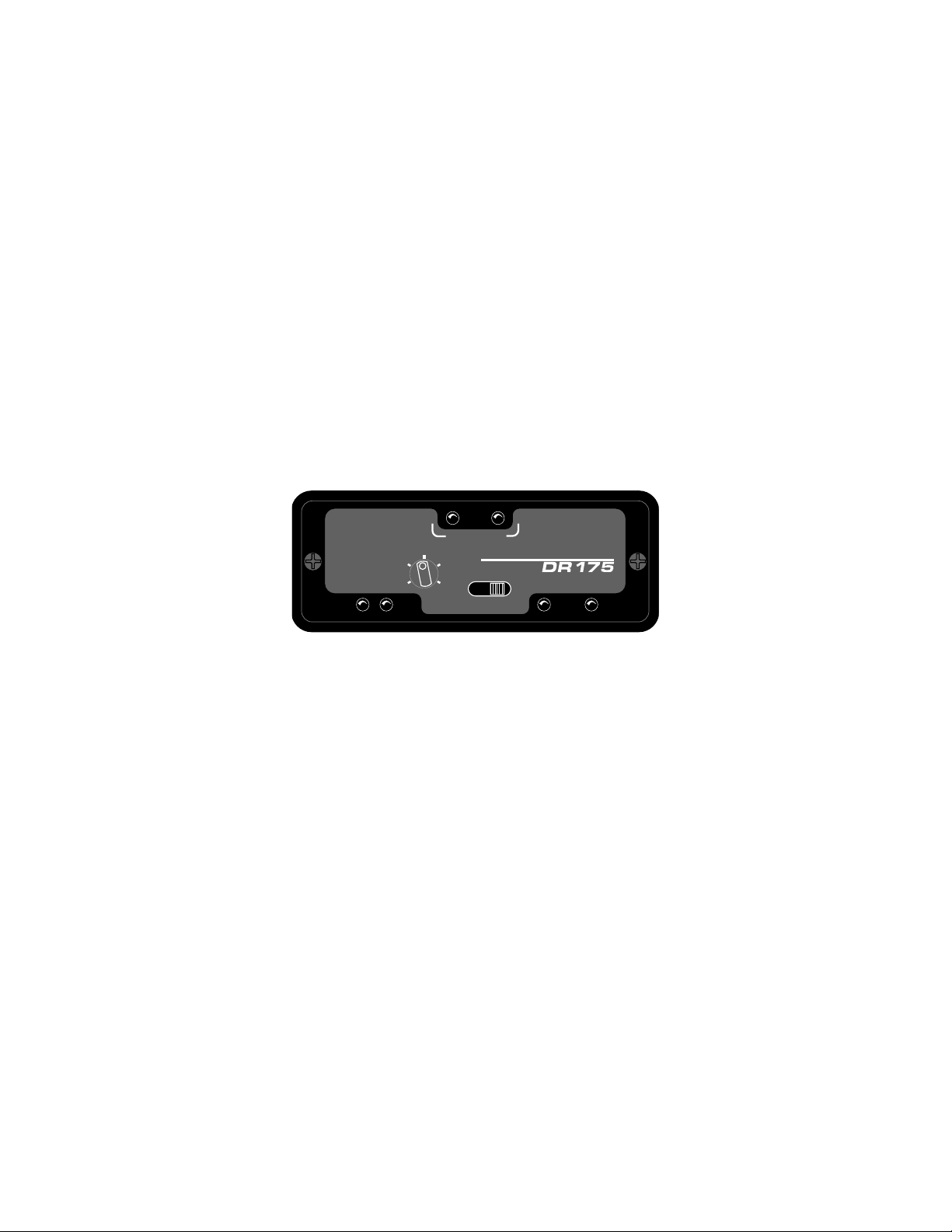
REAR PANEL CONTROLS AND FUNCTIONS
ANT B ANT A
AUDIO OUT 12V DC IN
PATENT
PENDING
1 2
3
ANTENNA INPUTS These inputs connect to any 50 ohm antenna with a BNC type connector.
12 VDC IN This input connects to the supplied CH-12 AC adapter for powering the receiver from a 110/120V AC
source. The receiver may also be powered from external 12 volt DC sources using the correct plug (Switchcraft
S-760 power plug). The center pin is positive. (+).
AUDIO OUT
This XLR type connector supplies a balanced, low impedance output at microphone level. The audio signal is
present on pins 2 and 3, while pin 1 is ground. The output level of this jack is controlled by the AUDIO LEVEL
control on the front panel of the receiver. Pin 2 is "hot" in terms of polarity.
Figure 2 - DR175 Rear Panel
4
Page 5

ANTENNA USE AND PLACEMENT
There are two antennas included with this receiver. The A170 AC is a whip antenna that connects to either
terminal on the rear panel of the DR175 receiver.
Position the antennas so that they are not within 3 or 4 feet of large metal surfaces. If this is not possible, try to
position the antennas so that they are as far away from the metal surface as is practical. It is also good to position
the receiver so that there is a direct "line of sight" between the transmitter and the receiver antenna. In situations
where the operating range is less than about 50 feet, the antenna positioning is much less critical.
A wireless transmitter sends a radio signal out in all directions. This signal will often bounce off nearby walls,
ceilings, etc. and a strong reflection can arrive at the receiver antenna along with the direct signal. If the direct and
reflected signals are out of phase with each other a cancellation may occur. The result would be a "drop-out." A
drop-out sounds like either audible noise (hiss), or in severe cases, may result in a complete loss of the carrier and
the sound when the transmitter is positioned in certain locations in the room. A drop-out normally sounds like
"hum" or "hiss." Moving the transmitter even a few inches will change the sound of the hum or hiss, or eliminate it.
A drop-out situation may be either better or worse as the crowd fills and/or leaves the room, or when the transmitter
or receiver is operated in a different location.
The DR175 receiver offers a sophisticated diversity design which overcomes drop-out problems in almost any
imaginable situation. In the event, however, that you do encounter a dropout problem, first try moving the antenna
at least 3 or 4 feet from where it was. This may alleviate the drop-out problem on that antenna. If drop-outs are
still a problem, try moving the antenna to an entirely different location in the room or moving the antennas in closer
to the transmitter location. By observing the OPTI-BLEND LEDs on the front panel, you can determine which
antenna is suffering weak signals.
Lectrosonics transmitters radiate power very efficiently, and the receivers are very sensitive. This reduces dropouts to an insignificant level. If, however, you do encounter drop-outs frequently, call the factory or consult your
dealer. There is probably a simple solution.
TRANSMITTER
PHASE
CANCELLATION
REFLECTIVE SURFACE
I
N
D
I
R
E
C
T
S
I
G
N
A
L
L
A
N
G
I
S
T
C
E
R
I
D
DIRECT SIGNAL
INDIRECT SIGNAL
MULTI-PATH DROPOUT
Figure 3 - Drop-outs
LECTROSON CS
RECEIVER
I
5
Page 6

OPERATING INSTRUCTIONS
1) Connect the power supply.
2) Attach and place the antennas.
3) Connect the audio cable.
4) Set the front panel AUDIO LEVEL control fully counter-clockwise and set the POWER switch to ON. Check to
see that the red POWER LED lights up.
5) Adjust the transmitter "gain". THIS IS PERHAPS THE MOST IMPORTANT STEP IN THE SET UP
PROCEDURE. See your transmitter manual (Operating Instructions section) for specific directions on the
proper gain adjustment of your particular transmitter.
6) After adjusting the transmitter gain, set the AUDIO LEVEL to a comfortable listening position.
7) Operate the system and adjust the receiver output level as required for your equipment. The input levels on
different VCR’s and PA equipment vary, which may require that you set the OUTPUT ATTENUATOR control in
an intermediate position. Try different settings and listen to the results. If the output of the receiver is too high,
you may hear distortion or a loss of the natural dynamics of the audio signal. If the output is too low, you may
hear steady noise (hiss) along with the audio.
INDICATOR QUICK REFERENCE
CODE LED - Not active on this model (DR175NC.)
POWER - This red LED lights up when the receiver is properly connected to a power supply and switched on.
MODULATION -- The audio level is indicated by these two LEDs, -20 and 0dB. The normal operating level occurs
when the -20 (green) LED is lighting up with the audio. The 0dB LED (red) lights up when the audio level is high
and the signal is being compressed in the transmitter. An extremely high audio level may cause distortion. If
neither LED lights up when audio is being produced through the system, the audio level is too low, which may
produce audible background noise (hiss) in the audio. The audio level is adjusted with the transmitter GAIN or MIC
LEVEL control.
OPTI-BLEND LEDs -- These green LEDs indicate the blending action of the panning circuit in response to the
comparison of signal to noise ratios in the two receivers. The audio from either receiver is being mixed into the
blend when the corresponding LED lights up. The brightness of these LEDs varies in proportion to the amount of
audio being utilized from the associated receiver.
6
Page 7

TROUBLESHOOTING
Before going through the following chart, be sure that you have a good battery in the transmitter and that the
transmitter power LED is indicating normally.
SYMPTOM POSSIBLE CAUSE
NO POWER LED 1) Receiver switch in "OFF" position
2) External 12 Volt power disconnected
3) CH-12 AC adapter disconnected
NO CODE LED Normal for this model (DR175NC.)
NO SOUND
AND NO MODULATION LEDS 1) Transmitter switch in "MUTE" position
2) Possible malfunction in the audio section of the transmitter
(See transmitter manual)
3) Check transmitter modulation LEDs for possible transmitter
problem
MODULATION LED’s ON
BUT NO SOUND 1) Receiver LEVEL control turned down
2) Audio cable disconnected
3) Recorder or sound system off, or not properly adjusted
DR175 REPLACEMENT PARTS and ACCESSORIES
Part No. Description
CH-12 110 Volt AC adapter for DR175 receiver.
A-170 AC 1/4 wave whip on a right angle BNC connector.
A-185 Coax Remote, folded-dipole antenna with coaxial cable.
A-185-BNC Telescoping 1/4 wave whip on a swiveling BNC connector.
A-200
Remote dipole antenna with aluminum mounting block; supplied with
one built-in telescoping whip and one detachable telescoping whip.
7
Page 8

SPECIFICATIONS AND FEATURES
Operating frequencies:
Sensitivity:
Signal/noise ratio:
Squelch quieting:
AM rejection:
Modulation acceptance:
IF Selectivity:
Third order intercept:
Diversity technique:
Audio outputs:
Antenna inputs:
Controls:
Indicators:
150 to 216MHz, crystal controlled
-110dBm for 20dB Sinad (0.7uV)
96dB flat; 99dB A-weighted
Greater than 109dB
Below the noise at all input levels
Greater than ±15kHz
150kHz interference bandwidth
-30dB @ ±200kHz
+5dBm
Dual receiver "opti-blend" audio combining
XLR: 200 Ohm bal.; 100mV max.
Dual BNC female; 50 Ohm impedance
• Front panel attenuator controls balanced outputs
• Power switch
• Red LED for power "ON"
• Dual modulation LEDs show transmitter audio
level
• Dual "opti-blend" LEDs display mixture ratio
Power requirements:
Power consumption:
Weight:
Dimensions:
• 12V DC (rear panel jack)
• 110V AC (using supplied CH-12 AC adapter)
170mA max
10.1 ozs
3¼" wide, 1¼" high, 5¼" deep
8
Page 9

SERVICE AND REPAIR
If your system malfunctions, you should attempt to correct or isolate the trouble before concluding
that the equipment needs repair. Make sure you have followed the setup procedure and
operating instructions. Check out the inter-connecting cords and then go through the TROUBLE
SHOOTING section in the manual
We strongly recommend that you do not try to repair the equipment yourself and do not have
the local repair shop attempt anything other than the simplest repair. If the repair is more
complicated than a broken wire or loose connection, send the unit to the factory for repair and
service. Don’t attempt to adjust any controls inside the units. Once set at the factory, the various
controls and trimmers do not drift with age or vibration and never require readjustment. There
are no adjustments inside that will make a malfunctioning unit start working.
LECTROSONICS service department is equipped and staffed to quickly repair your equipment.
In-warranty repairs are made at no charge in accordance with the terms of the warranty. Out of
warranty repairs are charged at a modest flat rate plus parts and shipping. Since it takes almost
as much time and effort to determine what is wrong as it does to make the repair, there is a
charge for an exact quotation. We will be happy to quote approximate charges by phone for out
of warranty repairs.
RETURNING UNITS FOR REPAIR
You will save yourself time and trouble if you will follow the steps below:
A. DO NOT return equipment to the factory for repair without first contacting us by letter or by
phone. We need to know the nature of the problem, the model number and the serial
number of the equipment. We also need a phone number where you can be reached 8 am
to 4 pm (Mountain Standard Time).
B. After receiving your request, we will issue you a return authorization number (R.A.). This
number will help speed your repair through our receiving and repair departments. The return
authorization number must be clearly shown on the outside of the shipping container.
C. Pack the equipment carefully and ship to us, shipping costs prepaid. If necessary, we can
provide you with the proper packing materials. UPS is usually the best way to ship the units.
Heavy units should be "double-boxed" for safe transport.
D. We also strongly recommend that you insure the equipment, since we cannot be responsible
for loss of or damage to equipment that you ship. Of course, we insure the equipment when
we ship it back to you.
Mailing address: Shipping address: Telephones:
Lectrosonics, Inc. Lectrosonics, Inc. (505) 892-4501
PO Box 15900 581 Laser Rd. (800) 821-1121
Rio Rancho, NM 87174 Rio Rancho, NM 87124 FAX: (505) 892-6243
USA USA
World Wide Web: http://www.lectrosonics.com email: sales@lectrosonics.com
9
Page 10

LIMITED ONE YEAR WARRANTY
The equipment is warranted for one year from date of purchase against defects
in materials or workmanship provided it was purchased from an authorized
dealer. This warranty does not cover equipment which has been abused or
damaged by careless handling or shipping. This warranty does not apply to
used or demonstrator equipment.
Should any defect develop, we will, at our option, repair or replace any
defective parts without charge for either parts or labor. If we cannot correct the
defect in your equipment, we will replace it at no charge with a similar new item.
We will pay for the cost of returning your merchandise to you.
This warranty applies only to items returned to us, shipping costs prepaid, within
one year from the date of purchase.
This warranty gives you specific legal rights. You may have additional legal
rights which vary from state to state.
LECTROSONICS, INC.
581 LASER ROAD
RIO RANCHO, NM 87124 USA July 2, 1999
 Loading...