

Page 1
DMTH4
Digital Telephone Hybrid
• 3-in/24-out digital matrix architecture
• Fully integrates with DM Series processors
• Telephone, codec and auxiliary inputs and outputs
• Two Acoustic Echo Cancellers - 126 ms tail time
• Line echo canceller - 30 ms tail time
• 6 filters plus compressor on each input
• 6 filters plus compressor/limiter on each output
• USB and RS-232 interfaces for setup and control
TECHNICAL DATA
• Fully balanced audio signal flow through entire system - no pin 1 problem
• Digital I/O ports for "daisy chaining" and to connect other LecNet 2 devices
• Proportional gain auto mixing algorithm with AutoSkew
The DMTH4 integrates telephone lines, video codecs and
external audio sources into the digital bus structure of DM
Series processors so these sources operate as though
they are another microphone or audio input in the sound
system. The unit is much more than just a telephone
interface. Instead, it is a complete DM Series digital
matrix processor, with a 3-in/24-out digital matrix, automatic mixing and comprehensive signal processing on
every input and output. In essence, it simply connects to
telephone lines, video codecs and external audio sources
instead of mic/line inputs and outputs and integrates
seamlessly with DM Series matrix processors.
The primary applications are in sound reinforcement and
conferencing systems in boardrooms, courtrooms,
worship centers, distance learning systems, hotels and
other applications with multiple microphones and loudspeakers. The design represents a milestone in DSP
technology in its basic architecture and in its processing
speed and efficiency.
The challenge in teleconferencing using a sound system
on one or both ends of a conference is to minimize echo
heard at the far end caused by the coupling between
loudspeakers and microphones in the local sound system.
As sound from the far end enters the local sound system
and is delivered by the loudspeakers in the local room, it
will enter the local microphones and be sent back to the
far-end. At the far-end the listeners will hear an echo of
their own speech.
™
- US Patent 5,414,776
The integration of adaptive gain proportional auto mixing*
with an all new proprietary echo canceller provides a
remarkable solution that is as easy to install and set up as
it is effective. Echo-free teleconferencing and clean local
sound reinforcement is provided even in poor acoustical
environments.
The DMTH4 shares the large digital matrix bus with other
DM Series processors to handle a wide range of sound
system requirements from a modest boardroom to large
systems with hundreds of inputs. Multiple units can be
stacked with multiple DM processors to handle very large
systems with multiple phone lines.
Extensive control capability is built into the unit with an
intuitive command structure to allow external control with
USB or RS-232 connections. Up to 128 macros can be
stored in internal memory. Each macro can contain up to
64 commands, with 115 characters in each command. A
built-in macro recorder greatly simplifies the creation of
and use of macros.
*US Patent 5,414,776
Rio Rancho, NM, USA
www.lectrosonics.com
Page 2
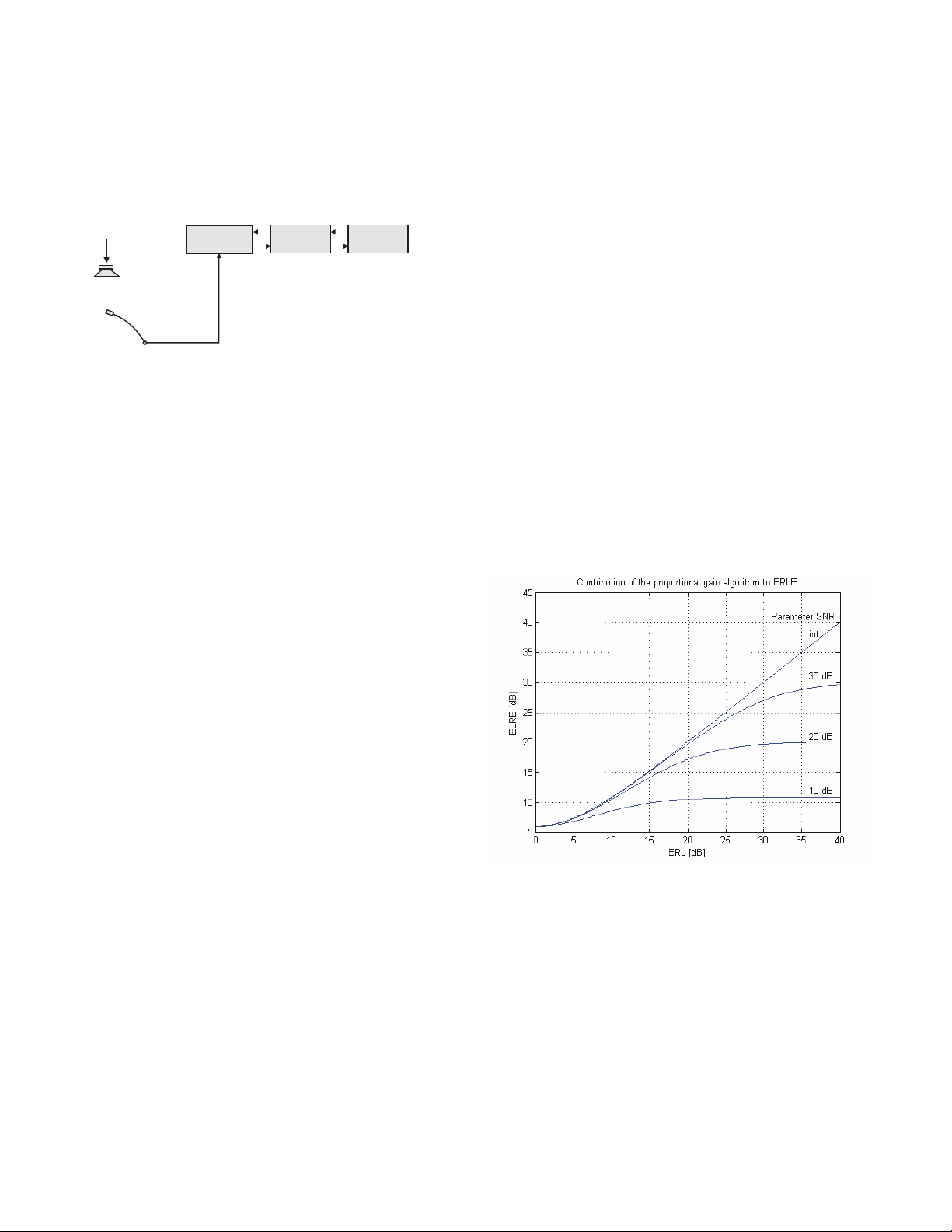
Echo and Echo Cancellation
The fundamental problem with microphone/speaker
acoustical coupling is illustrated below. Far end audio is
delivered by the loudspeakers in the room and the
microphones pick it up and return it to the far end. The
delay through this process creates an echo heard on the
far end.
Telephone
Interface
Far-end
Local
loudspeaker
Local
microphone
Local
sound system
There are several methods used to reduce or eliminate
the echo heard on the far end of the conversation:
• Optimal design in the sound system to minimize the
coupling between loudspeakers and microphones.
• Mix-minus matrix routing.
• Automatic microphone mixing.
• Digital echo cancelling.
Matters become more complex when the sound system is
required to provide both teleconferencing and sound
reinforcement. A gain proportional automatic mixing
process is widely recognized as the optimum solution for
sound reinforcement, but it places significant demands on
an acoustic echo canceller used for teleconferencing.
The matrix mixer enables complex signal routing and level
controls without limitations. The matrix mixing allows
"mix-minus" zoning of microphones and loudspeakers to
decouple them and reduce or eliminate acoustic feedback
and echoes. NOM attenuation is applied by the DSP at
the crosspoints in the matrix, which essentially provides
24 separate automatic mixers, each with its own NOM
mixing bus. Four different mixing modes can be selected
at the crosspoint for each input, so each input can participate differently in each output mix.
The automatic mixing process uses a seamless algorithm that eliminates gating and its ill-effects. Gain is
proportioned among all inputs assigned to a particular
output channel in a seamless and continuous manner
based upon microphone activity. The algorithm operates
in a natural, transparent manner and incorporates an
adaptive AutoSkew
™
process to eliminate artifacts such
as comb filtering and abrupt gating that occur with
conventional automatic mixing schemes. Audio from the
far-end of a conference participates in the local mixing
algorithm just like a microphone in the local sound
system.
Two digital acoustic echo cancellers are provided in the
DMTH4 to further reduce the return of local signals to the
far-end. One operates on the telco connection and the
other is dedicated to the video codec connection. In
conjunction with the automixing process, echoes are
minimized and not heard at the far end.
ERL
ERL (echo return loss) refers to the natural attenuation of
the far-end audio signal as it circulates from the far-end
through loudspeakers and microphones in the local sound
system and back to the far-end. Good design in the local
sound system will reduce the acoustic coupling between
loudspeakers and microphones using physical placement
and mix-minus matrix routing. Depending upon room size
and acoustics, it is often impossible to achieve adequate
decoupling to avoid an echo heard by the far-end during a
teleconference. Thus, other types of processing are
needed to further reduce the return echo.
ERLE
ERLE (echo return loss enhancement) refers to additional
circuits and processes used to further increase ERL.
Common methods are to use automatic mixing and digital
echo cancellation.
Return Loss Enhancement
The gain proportional automatic mixing algorithm* in the
DM Series processors not only provides seamless mixing
for local sound reinforcement without abrupt gating, but it
also contributes significantly to ERLE. The additional
contribution is plotted in the following graph.
Digital echo cancellation is another method of reducing
the echo delivered to the far-end. The concept, described
in very simple terms, is to have the DSP recognize the
far-end audio and subtract it from the transmitted audio to
remove any echo they might hear at the far-end. Sounds
simple, but in a sound system with multiple microphones
and loudspeakers, it is not easy to identify the far-end
audio in the complex mix of local sound, local noise and
the effects of the room on the far-end audio delivered by
the local loudspeaker system. When there is no sound or
noise in the local room, the DSP can do a decent job of
identifying the far-end audio and subtracting it from the
transmitted signal, but this is rarely the case in full duplex
teleconferencing. People talk, laugh and make noise, and
air conditioners and projectors make noise, etc.
2
Page 3

In a simple sound system arrangement, the local microphone can be muted when nobody is talking in the local
room. A simple gated mixer can provide this function.
With no open microphones locally, there is obviously no
return echo signal. This requires that a threshold level be
set high enough to keep the microphone from being
opened by background noise, but low enough to allow it to
open when someone speaks. When the local microphone
is open, a return echo path is created, which is when a
DSP echo canceller is needed. Given the wide variety of
human voices and the dynamics of noise in a meeting
room, a gated mixer is often not the best choice.
Using a dedicated DSP echo canceller on each input of
the local mixer (referred to as “distributed echo cancellation”) is an expensive but effective approach to reducing
the return echo. The process requires the algorithm to
“converge,” which is to identify the far-end audio and
subtract it from the signal sent to the far-end. This requires at least a brief moment when there is very little
local sound or noise, with significant far-end audio present
in the room. If nobody moves and there are no gain
changes made to local microphones and loudspeakers, it
is possible (in theory) to effectively remove return echo,
but this is not a very realistic situation.
The theory behind distributed echo cancelling is that once
the DSP has converged, it can continue to subtract far-end
audio even when the local microphone is open and far-end
audio is present at the same time. If there are any
changes in gain, noise or acoustics in the local space and
equipment, the DSP must re-converge, which requires
another brief moment with little or no local noise or sound,
and significant far-end audio present.
A gated automatic mixer does not change the gain when
the microphone is open, it just turns the channel off and
on abruptly. This helps with distributed echo cancelling
since the microphone is completely muted when not in
use, but it is very “choppy” sounding in the local sound
reinforcement system.
A gain proportional automatic mixer applies the most gain
to the most active microphone with smooth, continuous
changes. This makes it extremely effective for local sound
reinforcement, but the continuous gain changes make it
difficult for the echo canceller to remain converged and
effectively reduce the echoes at the far end.
The DMTH4 in conjuction with a DM Series processor
offers a unique approach to the problems with simultaneous teleconferencing and sound reinforcement. The
patented adaptive gain proportional mixing algorithm
works in conjunction with a centralized echo canceller to
address a variety of issues. The automatic mixer provides
seamless allocation of gain to local microphones through a
mix-minus matrix to reduce background noise and
decouple loudspeaker and microphones, while a very fast
converging DSP echo canceller operates on the composite
transmitted signal being sent to the far end. This combination of processes is possible only with the latest DSP
technology.
The auto mixing algorithm adapts to changes in background noise continuously, and unlike a gated mixer there
are no threshold levels to adjust. A sum of all channels is
the reference signal, each channel level is compared to
this reference and the individual channel gain is adjusted
to apply NOM attenuation. Gain is adjusted continuously
to eliminate audible artifacts that gating and abrupt level
changes can cause. As the common mode noise in the
room changes, all channels are affected equally. The end
result is seamless, adaptive auto mixing that requires no
calibration or threshold adjustments.
Each individual output of the matrix operates as a separate NOM bus, so a particular input can be assigned to
multiple outputs with mix parameters adjusted differently
for each output. In other words, gain and mix mode are
configured independently for each matrix crosspoint,
resulting in great flexibility. Four mix modes are supported: Auto, Direct, Override and Background.
The echo canceller converges continuously when the
level of the far side signal exceeds a minimum level, and
the ratio of the far side signal to local room sound exceeds a minimum ratio. This dynamic control prevents
divergence during periods of silence from the far side
room or in “doubletalk” situations. The convergence takes
place very quickly to keep up with the changes made by
the automatic mixing algorithm and other changes that
occur in the room. Setup is greatly simplified and any
adjustments, such as level changes made with a remote
control system, are accommodated automatically.
The convergence speed is adjustable in the control panel
GUI to fine tune it to a particular situation. Faster convergence times can track changes in the room almost
instantaneously, but the depth of echo cancellation will be
reduced. Slower convergence times take a bit longer to
fully converge, but produce greater echo cancellation.
The ERLE value achieved by the echo canceller is
displayed on the GUI and the effects of altering the
convergence rate will be immediately visible and audible.
An important final note on the DMTH4 is the fact that the
echo canceller will never “diverge” (lose convergence).
This unique algorithm will also converge on a continuous
sine wave, which is especially important when DTMF
tones are present in the room. Since the echo canceller
will never diverge, there is no need for a “panic button” (as
is used in other designs) to generate a noise burst to help
the echo canceller re-converge.
3
Page 4

General Overview
The DMTH4 integrates telephone lines, video codecs and
external audio sources into the digital bus structure of DM
Series processors, allowing these audio signal sources to
operate as though they are another microphone or audio
input in the local sound system. This is a complete DM
Series digital matrix processor, with a 3-in/24-out digital
matrix, automatic mixing and comprehensive signal
processing on every input and output.
The latest generation DSP microchips and microprocessors are the core of the engineering of the DM Series and
the DMTH4 is no different. The focus and purpose is to
meet the requirements of modern applications and also
the demands for convenience and automation.
The DMTH4 is configured through the DMTH4 Control
Panel which is part of LecNet2™, a user-friendly, yet
powerful control program. The Control Panel offers quick
configuration and full command of the system through
either a USB or RS-232 compatible interface. Once
configured, it operates independently.
All models in the DM Series offer the same signal processing functions, and vary only by the number of audio
inputs and outputs available. The DM's basic structure
consists of three stages: Input, Matrix and Output. (See
DMTH4 Signal Flow Block Diagram
tional Block Diagram
24 Output Submixes 12 Backpropogated Final Mixes
2 Expansion Submixes
26 Automixing Aux. Data
TEL
Input
Processing
Codec
Input
Processing
Aux
Input
Processing
2 Expansion Submixes
26 Automixing Aux. Data
DMTH4 Signal Flow Diagram
.)
3 by 24
Automatic
Mixing
Matrix
24 Output Submixes
2 Expansion Signals
26 Automixing Control Data
2 Expansion Signals
26 Automixing Control Data
and
DMTH4 Func-
1 kHz, 0 dBu
TEL
Output
Processing
Codec
Output
Processing
Aux
Output
Processing
Ton e
Generator
Pink Noise
Generator
0 dBu
DTMF
Generator
0 dBu
Each input channel includes a high quality 24-bit A-D
converter. Extensive digital signal processing is provided
on each input channel. Each input channel is processed
and filtered as needed and the signal is delivered into the
matrix.
The digital matrix mixer distributes each input signal to
any selected combination of mix busses, with level control
at each crosspoint. The matrix processes the signals and
communicates them to other devices in the system. Each
output receives signals from the mixing matrix, the pink
noise generator or the tone generator as needed for
setup, diagnostics or operation. Each of the 3 outputs
includes extensive signal processing to optimize the
mixed signal for the intended purpose, such as sound
reinforcement, recording or teleconferencing.
The DMTH4 is integrated into a system of DM Series
automixers using the Digital Audio Network Interface
(DANI). DANI connects the digital audio outputs of the
units through standard RJ45 connectors.
When DM Series automixers are stacked, mixing data
and the digital audio are passed between the slave units
and the master unit through the DANI. Multiple units can
be stacked in a master/slave configuration to expand the
number of inputs to hundreds of channels. The DMTH4 is
designed to be the end slave unit of a DM Series stack.
The audio and data from all units in the stack is gathered
in the matrix in the master unit, which is where the final
mix signals are generated. The first 12 final mix signals
from the master are back propagated through the DANI to
each slave. (See
DM1624 Master
DM1624 and DMTH4 Slaves
DM Series Back Propogation Diagram
with
Master
DM1624
Slave
DM1624
Slave
DMTH4
Outputs
Outputs
DM Series Back Propagation Diagram
DM1624 Master
DM1612 and DMTH4 Slaves
1
24
1
Outputs
12
1(13)
Outputs
12(24)
Codec
TEL
AUX
with
Master
DM1624
Slave
DM1612
Slave
DMTH4
1
12
13
24
1
Outputs
12
Outputs
Codec
Master and
Slave Outputs
Master only
TEL
AUX
DM812 and DMTH4 Slaves
Outputs
DM1612 Master
with
Outputs
Master
DM1612
Outputs
Slave
DM812
Outputs
Slave
DMTH4
.)
1
12
1
12
Codec
TEL
AUX
4
Page 5

Mixing Mode
The automatic mixing algorithm applies a patented gain
proportional algorithm (
#5,402,500
) allowing each input assigned to a particular
output to behave differently relative to the other inputs
assigned to the output.
Four different mixing modes are available:
Auto - In automatic mode the input applied to the
crosspoint is mixed into the output channel using
the the Adaptive Proportional Gain automixing
algorithm in the normal manner. This is the most
common setting.
Direct - In Direct mode the automixing algorithm is
bypassed.
Override - Override mode is selected when it is
required that the input applied to the crosspoint
always dominates the output channel when it
becomes active.
Background - Background mode is selected when
it is required that the input applied to the crosspoint
dominates the output channel only when all other
inputs are inactive.
US Patents #5,414,776
and
DMTH4 Functional Block Diagram
Digital Matrix
The digital matrix provides signal routing and communication with other devices in the system, and applies automatic mixing and level control. (See
tional Block Diagram
.)
Automixer Cell
The Automixer Cell is the core of the matrix. It is where
level control for the automatic mixing algorithm, mixing
mode and crosspoint gain is applied to data gathered
from other channels and devices. The cell receives data
from the master unit in a multiple unit stacked configuration and from the slave units farther down in the chain.
Power of the Mix
The Power of the Mix is the reference used to determine
the gain to be applied to each individual output channel.
In a multi-unit stacked configuration, this data is sent to
the slaves from the master unit.
Digital Matrix Func-
Power of the Mix
Audio Input
Power of the
Submix
Automixer
Cell
Power of the
Submix
Mixing Mode
- Auto
- Direct
- Override
- Background
Crosspoint Gain
-70 to 20 dB
1 dB steps
One of 72 Matrix Crosspoints
Submix
+
Submix
Crosspoint Gain
Crosspoint Gain is the gain selected with the control
panel that determines the level at the output.
Digital Matrix Functional Block Diagram
(Typical Matrix Crosspoint)
5
Page 6

LecNet2 Software
Software is included with the DMTH4 and available for
download from the website at:
www.lectrosonics.com
The software is used primarily for setup, with the configuration saved on file and into the unit's memory for actual
operation. Once configured, the DMTH4 runs without a
host computer.
The software is user-friendly, with a variety of screens
provided for each section of the signal flow and system
design. The software runs under Windows
®
2000 and XP
operating systems using a familiar tabbed layout. A few
sample screens are shown below.
.
Input Processing
Each input channel provides individual stages for gain,
filtering and compression.
Input Gain
The input applies software controllable gain with a level
indicator and clipping indicator.
Filters
Up to six filters can be implemented at each input to
idealize the signal equalization.
The filter types include:
Low pass
High pass
Band pass
Parametric EQ
Low shelving
High shelving
Filter slopes can be selected with 6 or 12 dB per octave
Butterworth or Bessel parameters. Multiple filters can be
assigned to create steeper slopes in 6 dB steps.
Input Compressor
The compressor implementation is a unique “soft knee”
type based on an RMS level detector controlled by a
single time constant parameter. This is a new design
which responds to varying rates of change in the signal
level by dynamically adjusting the attack and release
times for best performance. Adjustment is simplified by
entering a single value (half of the desired release time).
The attack time is then applied by the DSP to vary with
the signal.
The default value is 100 ms, which sets the release time
at about 200 ms. The attack time is signal controlled and
varies from about 2 ms to about 100 ms as is needed to
handle the signal dynamics. See the reference manual
for a closer look at this unique and very effective compressor.
Compressor adjustment parameters include:
Threshold
Time Constant
Compression ratio
Makeup gain
Indicator
Cl ipping
Detector
A/D
Six F ilter
Gain Reduction Indicator
Stages
Activi ty Indicator
Compressor
Indicator
Level M eter
*Windows is a registered trademark of Microsoft Corp.
6
Coarse Gain
0 t o 12 dB,
3 dB s teps
Input Gain & Polari ty
-10 to +60 dB
1 dB steps
Fine Gai n & Polari ty
-10 to 10 dB,
1 dB s teps
One of 3 Input Signal Processing Block s
Off, LP, HP, BP,
PEQ, LS, HS
6 or 12 dB /oct.
ButteRwor th or Bes sel
when appl icable
Typical Input Signal Processing Blocks
Threshold
Comp. Ratio
Ti me Const ant
Page 7

Output Processing
Output Source Select
The TEL, CODEC and AUX outputs can each be set to
receive a signal from the pink noise generator, the tone
generator, the expansion outputs or from the master unit
outputs. The pink noise source can be used for sound
masking during operation, and for equalization during
setup. The tone generator is used for level adjustments
and signal routing diagnostics. The DTMF generator is
used to create the DTMF tones for initiating calls.
In normal operation the digital matrix delivers the audio
signals to the outputs, which consist of the final mixes
backpropagated from the master unit in the system via
the Digital Audio Network Interface (DANI), with 12 mixes
from the main matrix and 2 mixes from the expansion
matrix.
CODEC and AUX Output Channels
These outputs include an attenuator to reduce the output
level from line to mic level. The passive attenuator does
not change the signal to noise ratio of the signal, but
simply applies user selectable 20 dB or 40 dB of attenuation to reduce the signal level.
Output Signal Processing Stages
Each output channel provides six filters plus a compressor and limiter to idealize the channel for its function in
the sound system. (See
Block
)
Output Gain and Level Indicator
The output level can be adjusted from - 70 dBu to +20
dBu in 1 dB steps to perfectly match the requirements of
the device being fed by the channel. A bar graph is
provided by the on screen GUI to accurately indicate the
output level as it operates and is adjusted.
Typical Output Signal Processing
Output Compressor and Limiter
A versatile compressor and limiter are provided at each
output to control the average level and dynamics of the
audio signal, and restrict the maximum output level to
optimize the channel for its purpose. Compression is
often needed when the channel is feeding a recorder, and
limiting is often used to protect a loudspeaker system and
reduce distortion and amplifier overload.
The compressor implementation is a unique “soft knee”
type based on an RMS level detector controlled by a
single time constant parameter. This is a new design
which responds to varying rates of change in the signal
level by dynamically adjusting the attack and release
times for best performance. Adjustment is simplified by
entering a single value (half of the desired release time).
The attack time is then applied by the DSP to vary with
the signal.
The default value is 100 ms, which sets the release time
at about 200 ms. The attack time is signal controlled and
varies from about 2 ms to about 100 ms as is needed to
handle the signal dynamics. See the reference manual
for a closer look at this unique and very effective compressor.
Compressor adjustment parameters include:
Threshold
Time Constant
Compression ratio
Makeup gain
Limiter adjustment parameters include:
Threshold
Time Constant
Filters
Up to six filters can be implemented at each output to
idealize the signal equalization.
The filter types include:
Low pass
High pass
Band pass
Parametric EQ
Low shelving
High shelving
Filter slopes can be selected with 6 or 12 dB per octave
Butterworth or Bessel parameters. Multiple filters can be
assigned to creater steeper slopes in 6 dB steps.
Activi ty Indicator
Gain Reduction Indicator
Six F ilter
Stages
Off, LP, HP, BP,
PEQ, LS, HS
6 or 12 dB /oct.
Butterworth or Bessel
when appl icable
Typical Output Signal Processing Blocks
Compressor Lim iter
Threshold
Comp. Ratio
Tim e Constant
Activi ty Indicator
Ti me Cons tant
Threshold
Indicator
Output Gain
-70 - +20 dB
1 dB steps
Level Meter
7
Page 8

Front Panel
R
TELEPHONE HYBRID INTERFACE
The DMTH4 is housed in a single space 19” rack mount
assembly. The front panel provides a Mode switch to
allow booting the unit as a Master when it is configured as
a Slave and powered up by itself. The Status LED
indicates steadily in normal operation and blinks in the
presence of several different errors.
Rear Panel
16: IN 4
17: IN 6
18: IN 8
19: IN 10
20: +5V
21: OUT 2
22: OUT 4
23: OUT 6
24: OUT 8
25: +5V
TX RX
RX
EXPANSION TEL RC
POWER
90-240V 50/60Hz 15W
This device complies with
Part 15 of the FCC rules.
Operation is subject to the
following two conditions: (1)
This device may not cause
harmful interference, and (2)
this device must accept any
interference received, including
interference that may cause
undesired operation.
6: IN 9
1: GND
1
14
LecNet 2
RS-232
USB
13
25
2: IN 1
7: IN 11
8: GND
3: IN 3
9: OUT 1
4: IN 5
10: OUT 3
5: IN 7
11: OUT 5
12: OUT 7
13: GND
14: +5V
15: IN 2
PROGRAMMABLE
INPUTS / OUTPUTS
AB
A universal 100-240 VAC universal power supply is
included on the rear panel with a standard 3-pin receptacle. The USB and RS-232 jacks are used to connect to
a computer for setup, or to control systems for operation.
Logic input and output connections are made via a DB-25
jack. RJ-45 jacks interface with other DM Series components.
Specifications
Echo Canceller (3 Total): 2 Acoustic - 126 mS tail time
Telephone Line Return Loss: 45 dB
Audio inputs (Codec, AUX):
Gain: -20 dB to +20 dB, programmable in
Input impedance: 10 k Ohm
Connector: 5-pin Phoenix
Audio outputs (Codec, AUX): Floating balanced, either side can be
Nominal level: 0 dBu all outputs, -20 and -40 dBu
Output impedance:
0 dB Attenuation: • 450 Ohms differential
-20 dB Attenuation: • 50 Ohm differential
-40 dB Attenuation: • 5 Ohm differential
Input Dynamic Range
(Codec, AUX): 102 dB (unweighted 20 - 20 kHz)
Output Dynamic Range
(Codec, AUX): 105 dB (unweighted 20 - 20 kHz)
Audio Performance (Codec, AUX):
IMD + noise: 0.1% max.
THD + noise: 0.1% (worst case)
EIN: -126 dBu
1 Line - 30 mS tail time
Will never diverge, regardless of signal
type (i.e. sine wave)
1 dB steps
grounded
selectable
0.02% nominal input level
0.02% nominal input level
POWERUSBSTATUSMODE
A USB port on the front panel allows easy access for
setup or troubleshooting from the front side of the rack.
The power switch is a rocker type with positive action.
CODEC RC
TX
MIC/LINE
OUTPUTS
CODEC AUX
CODEC AUX
LINE
INPUTS
TELEPHONE
SET LINE
Complies with Part 68 FCC rules.
Registration Number:4J3BR09BDMTH4
Ringer Equivalence:
LECTROSONICS, INC.
0 . 9 B
U.S. Patent Number: 5,414,776
TELEPHONE HYBRID
MADE IN U.S.A.
Codec and telephone wall plate and desktop remote
control accessories connect through a dual RJ45 connector. Codec and auxiliary inputs and outputs are made via
depluggable connectors. The telephone line and handset
are connected through standard RJ-11 jacks.
Connectors:
Audio I/O: 5-pin “Phoenix” type
Expansion: RJ45
Logic I/O: DB25
Serial: Standard USB and mini TRS
Proprietary network
Physical level: LVDS (Low Voltage DIfferential Signal)
Connector: Four RJ-45
Cable quality: Shielded CAT-5
Transmission speed: 50 Mbits/s
Programmable control inputs
Number of inputs: 11
Analog voltage range: 0-5V
Logic input: TTL, LVTTL, CMOS, LVCMOS
Programmable control outputs
Number of logic outputs: 8
Logic control: active low
Max sink current: 100 mA
Max supply voltage: 40 V
Supply voltage for control I/O: 5 V
Max current: 750 mA
Power requirements: 100-240 VAC, 47-63 Hz
Power consumption: 15 Watts
Dimensions:
Faceplate: Standard 19 inch 1RU
Housing: 17.500” W x 1.710” H x 7.500” D
Weight: 1595 grams; 3.516 lbs. without AC cord
high speed
(no ventilation requirements - no fan)
581 Laser Road NE • Rio Rancho, NM 87124 USA • www.lectrosonics.com
(505) 892-4501 • (800) 821-1121 • fax (505) 892-6243 • sales@lectrosonics.com
21 November 2005
 Loading...