

Page 1
HARDWARE and SOFTWARE INSTALLATION GUIDE
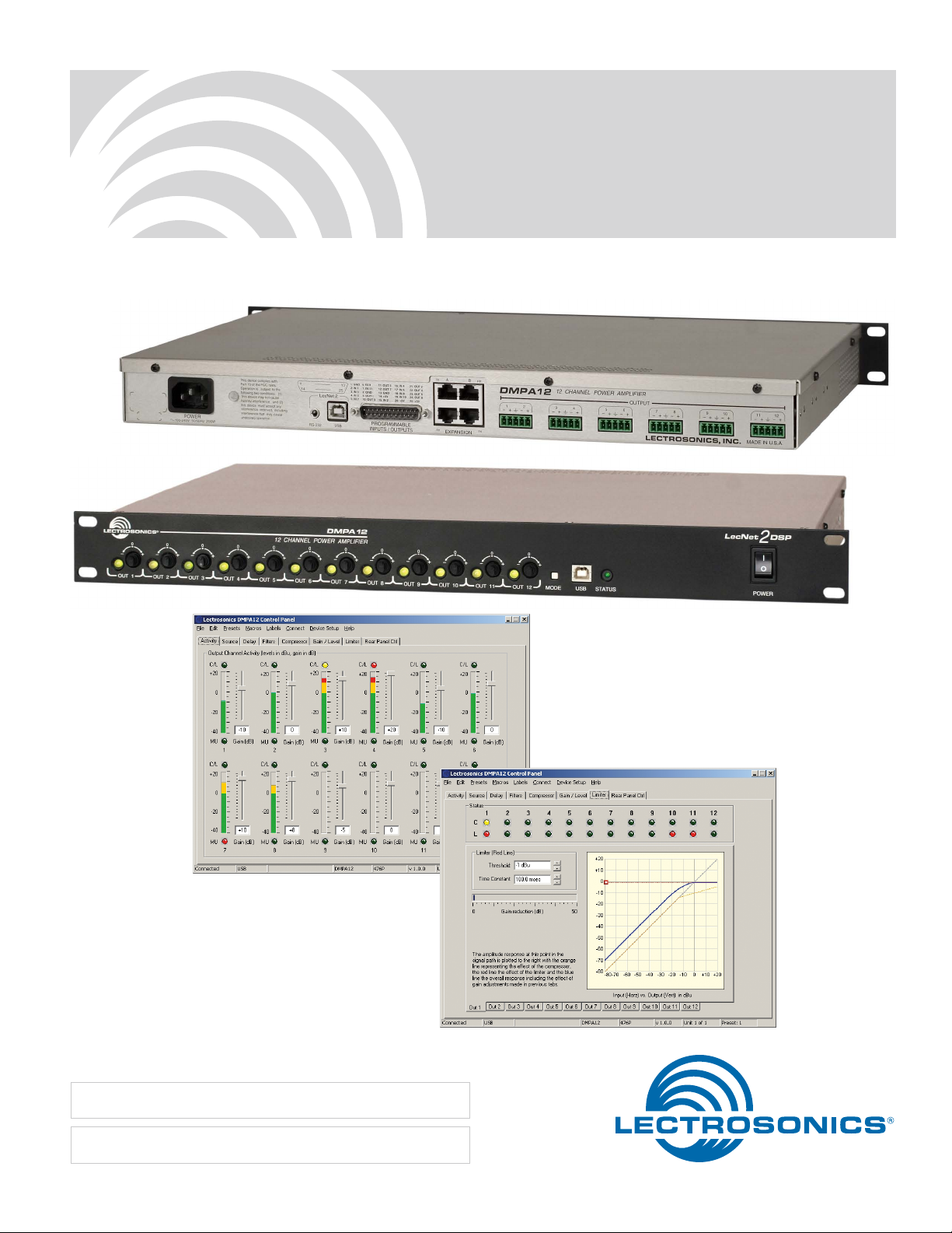
DMPA12
Digital Power Amplifier
Fill in for your records:
Serial Number:
Purchase Date:
Rio Rancho, NM, USA
www.lectrosonics.com
Page 2

DMPA12 Installation Guide
2
LECTROSONICS, INC.
Page 3
DMPA12 Installation Guide
Important Safety Instructions
This symbol, wherever it appears, alerts you to the presence of uninsulated dangerous voltage inside the
enclosure -- voltage that may be sufficient to constitute a risk of shock.
This symbol, wherever it appears, alerts you to important operating and maintenance instructions in the
accompanying literature. Please read the manual.
1) Read these instructions.
2) Keep these instructions.
3) Heed all warnings.
4) Follow all instructions.
5) Do not use this apparatus near water.
6) Clean only with a dry cloth.
7) Do not block any ventilation openings. Install in accordance with the manufacturer’s instructions.
8) Do not install near any heat sources such as radiators, heat registers, stoves, or other apparatus (including amplifiers) that produce heat.
9) Do not defeat the safety purpose of the polarized or grounding-type plug. A polarized plug has two blades with
one wider than the other. A grounding type plug has two blades and third grounding prong. The wider blade or
the third prong are provided for your safety. If the provided plug does not fit into your outlet, consult an electrician for replacement of the obsolete outlet.
10) Protect the power cord from being walked on or pinched particularly at plugs, convenience receptacles, and the
point where they exit from the apparatus.
11) Only use attachments/accessories specified by the manufacturer.
12) Use only with the cart, stand, tripod, bracket, or table specified by the manufacturer,
or sold with the apparatus. When a cart is used, use caution when moving the
cart/apparatus combination to avoid injury from tip-over.
13) Unplug this apparatus during lightning storms or when unused for long periods of
time.
14) Refer all servicing to qualified service personnel. Servicing is required when the
apparatus has been damaged in any way, such as power-supply cord or plug is
damaged, liquid has been spilled or objects have fallen into the apparatus, the apparatus has been exposed to rain or moisture, does not operate normally, or has
been dropped.
15) WARNING -- TO REDUCE THE RISK OF FIRE OR ELECTRIC SHOCK, DO NOT EXPOSE THIS APPARATUS
TO RAIN OR MOISTURE.
16) The AC mains plug, or appliance coupler shall be readily available to the operator as a means of power disconnection.
17) Unit shall be connected to a MAINS socket outlet with a protective earthing connection.
Rio Rancho, NM
3
Page 4

DMPA12 Installation Guide
Table of Contents
Important Safety Instructions................................................ 3
Introduction ............................................................................. 5
Unpacking the Unit ................................................................ 5
Items Included in the box: ..................................................... 5
Hardware Installation ............................................................. 6
Rack Installation .................................................................... 6
Cables and Power Cord ........................................................ 6
Audio Inputs ......................................................................... 6
Speaker Outputs ................................................................... 6
DMPA12 Rear Panel ............................................................. 8
Programmable Inputs ............................................................ 8
Programmable Outputs ......................................................... 8
Programmable Inputs and Outputs Wiring ............................ 9
Control System Interconnections .......................................... 9
Installing LecNet2 Software and USB Driver ..................... 10
Installation with LecNet2 Device Installer ........................... 10
Manual Installation .............................................................. 11
Initial Setup ........................................................................... 13
Connect ............................................................................... 13
Select the Signal Source ..................................................... 14
Initial Setup Hints ................................................................ 15
Additional Settings and Functions ..................................... 16
Compressor and Limiter ...................................................... 16
Front Panel Gain Controls ................................................... 16
Front Panel Output Activity Indicators .................................. 17
Output Fault Indications ...................................................... 17
Expansion Mode Setup ....................................................... 17
RS-232 Baud Rate Adjustment ........................................... 17
Connect Options ................................................................. 18
Note: This equipment has been tested and found to comply with the limits for a Class A digital
device, pursuant to Part 15 of the FCC Rules. These limits are designed to provide reasonable protection against harmful interference when the equipment is operated in a commercial environment.
This equipment generates, uses, and can radiate radio frequency energy and, if not installed and
used in accordance with the instruction manual, may cause harmful interference to radio communications. Operation of this equipment in a residential area is likely to cause harmful interference in
which case the user will be required to correct the interference at his own expense.
CAUTION: Changes or modifications not expressly approved by Lectrosonics, Inc. could void the
user’s authority to operate the equipment.
This device complies with Part 15 of the FCC Rules. Operation is subject to the following two conditions: (1) This device may not cause harmful interference, and (2) this device must accept any
interference received, including interference that may cause undesired operation.
4
LECTROSONICS, INC.
Page 5

Introduction
The purpose of this guide is to assist in the correct
installation and initial setup of a DMPA12 digital power
amplifier in a sound system utilizing other DM Series
components. This guide assumes familiarity with the
DMPA12 amplifier and other components and software
used in the system. To get the most out of this power
amplifier, it is suggested that you review the information
presented in the Reference Manual, available on the
supplied CD or downloaded from the web site at:
http://www.lectrosonics.com/LecNet2/
A detailed online Help is also available to assist in the
setup and operation of this power amplifier using the
USB interface and a computer system running Windows XP, Vista and 7 operating systems. In addition to
assistance setting up and operating this amplifier, the
Help includes a complete listing of Commands. These
commands can be used to setup and operate the amplifier via external devices using either the USB or RS232
serial port.
Unpacking the Unit
Compare the packing list enclosed with the unit with
the original order. Inspect all items for damage. Immediately call 1-800-821-1121 to report any items that
are missing or damaged. The sooner we get notified,
the sooner we can get any needed replacement items
shipped to your location.
DMPA12 Installation Guide
Items Included in the box:
Description Quan. Part Number
Installation Guide 1 M-DMPA12-I
Warranty Card 1
Power cable 1 21499
5-pin Phoenix connector 6 21580
25-pin connector 1 21558
LecNet serial cable, black
DB-9 to 3.5mm stereo
plug
LecNet serial cable, red
DB-9 to 3.5mm stereo
plug
for AMX, Crestron
USB interface cable 1 21713
CAT-5 interconnect cable 2 21716
Small screwdriver 1 35679
Rack Mount Support Kit:
Siderail 2 26693
Screws 6 28505
Washers 6 28402
1 21529-1
1 21710-1
If there are any problems or items missing,
immediately call 1-800-821-1121 and ask for
anyone in sales or service.
Rio Rancho, NM
5
Page 6

DMPA12 Installation Guide
Hardware Installation
Rack Installation
The DMPA12 occupies a single rack space and there
are no special ventilation requirements. Mount with 4
rack screws through the ears on the front panel.It is
recommended to use nylon washers to prevent damage
to the front panel’s finish when tightening the screws.
While it is not mandatory, it is good practice to leave an
empty rack space above the amplifier.
The amplifier should be mounted in a rack with rear
support rails. Adjustable brackets are provided.
Cables and Power Cord
It is recommended to use lacing bars for cable strain
relief when mounting in a rack. Use only professional
grade audio, either a twisted pair type or two conductors plus ground/shield.
The power input jack is a standard 3-pin type that accepts commonly available cords with IEC 60320 C13
connectors – the same type 3-pin socket typically used
on computers and peripherals with built in power supplies. The internal switching power supply will handle
voltages ranging from 100 VAC to 240 VAC for use with
power sources outside of North America.
Rear support brackets are included with the amplifier
+
-
Loudspeaker wiring with unshielded twisted pair
+
-
Audio Inputs
Input signals are delivered from DM Series processors
into the power amp via the DANI (digital audio network
interface) bus using the supplied CAT-5 cables connected to the Expansion ports.
There are no
analog audio
inputs to the
amplifier
Speaker Outputs
All outputs are a balanced differential configuration and
can be used with shielded or unshielded cabling. Two
adjacent outputs can be combined to double the power
delivered to a loudspeaker by wiring them in parallel.
NOTE: The design of the Class D amplifier
requires that adjacent channels be wired in
parallel in order to combine them. This is different
than the wiring used to bridge the outputs on a
conventional analog power amplifier.
+
-
Loudspeaker wiring with shielded cables
+
-
+
-
+
-
NOTE: When the outputs are wired
this way, the same signal source and
DSP processing must be selected for
both outputs. See the Source Tab in the
software GUI for this selection.
Two adjacent outputs can
be combined to double the
available power for one
loudspeaker by wiring two
adjacent outputs in parallel.
WARNING: DC voltage is present on the
outputs, which are designed to operate ONLY
in a balanced configuration. If either the (+) or
(-) pins are grounded, the outputs that share
that connector will automatically shut down
and a fault will be indicated on the front panel
(blinking orange LEDs).
6
LECTROSONICS, INC.
Page 7

DANI Bus (expansion ports)
12
12
Audio Final Mix and
Expansion I/O ports
The four RJ45 connectors on the rear panel are used to
interconnect LecNet2™ units together. These ports are
only used to transfer digital audio information via the
Digital Audio Network Interface (DANI) between the DM
Series processors that are interconnected.
WARNING: The Expansion I/O connectors are
NOT EtherNet, CobraNet or any other network
based device interconnects. Connecting them
to Ethernet, CobraNet or other network based
device may cause damage to either unit.
To connect the Master/Slave units, plug one end of a 12
inch Cat5e cable (two are supplied with each with unit)
to the transmit (TX) port on the Master unit, and connect the other end to the corresponding receiver (RX)
port on the Slave unit immediately below the Master.
Repeat this procedure with the second Cat5e cable.
(See Expansion Port Digital Audio Network Interface
Interconnection Diagram.)
16: IN 4
17: IN 6
18: IN 8
19: IN 10
20: +5V
MMABLE
UTPUTS
16: IN 4
17: IN 6
18: IN 8
19: IN 10
20: +5V
21: OUT 2
22: OUT 4
23: OUT 6
24: OUT 8
25: +5V
21: OUT 2
22: OUT 4
23: OUT 6
24: OUT 8
25: +5V
AB
TX
RX TX
EXPANSION
AB
TX
RX
RX
DMPA12 Installation Guide
Interconnection Diagram
The DMPA12 amplifier, like all DM Series processors,
are interconnected via the Expansion ports on the
rear panel. The correct wiring to stack multiple units
is shown here. To ensure proper signal and data flow,
the TX port on a slave connects to the RX port directly
above it in the stack. The TX port on the upper unit connects to the RX port on the unit below it.
Data Back Propagation
Master
Slave
Slave
Slave
Slave
Audio Submix and
Data Forward Propagation
AB
TX
RX TX
EXPANSION
AB
TX
RX TX
EXPANSION
AB
TX
RX TX
EXPANSION
AB
TX
RX TX
EXPANSION
AB
TX
RX TX
EXPANSION
RX
RX
RX
RX
RX
MMABLE
UTPUTS
Rio Rancho, NM
RX TX
EXPANSION
Audio signals and data are propagated through the DANI
bus via Cat5e cables connected to the Expansion ports
on the rear panel.
7
Page 8

DMPA12 Installation Guide
100-240V 50/60Hz 200W
1: GND
2: IN 1
3: IN 3
4: IN 5
5: IN 7
25
13
14
1
6: IN 9
7: IN 11
8: GND
9: OUT 1
10: OUT 3
11: OUT 5
12: OUT 7
13: GND
14: +5V
15: IN 2
16: IN 4
17: IN 6
18: IN 8
19: IN 10
20: +5V
21: OUT 2
22: OUT 4
23: OUT 6
24: OUT 8
25: +5V
AB
TX
RX
RX TX
12
OUTPUT
34 56 78 910 11 12
Potentiometer Connection for
LED is on when the programmable output is active
DMPA12 Rear Panel
Programmable
Inputs and Outputs
Programmable Inputs
Programmable inputs are provided to enable external
control over a variety of parameters. Each input can
respond to either a contact closure or a continuous
voltage. The following illustrates common connections
to the programmable input pins. (See also Program-
mable Inputs and Outputs Wiring Diagram.)
No external pull-up resistors are necessary because
each programmable input is internally pulled up through
a 100K resistor to +5V. When using a continuous voltage with one of the programmable inputs, the function
of the programmable input must be set to Analog Out-
put RP Gain Control on the Programmable Inputs
control tab in the Control Panel GUI. See the Program-
mable Input tab in the Control Panel software Help for
setting all programmable input parameters.
Analog Control of Gain
10K Linear Potentiometer
CCW
CW
+5V
To Programmable Input Pin
Gnd
Expansion I/O Ports
Programmable Outputs
Programmable outputs are used to indicate the current
state of a programmable input or to indicate some other
feature of the DMPA12. Each programmable output is
the electrical equivalent of a contact closure to ground.
When a programmable output is “active”, it conducts
current to ground. When the programmable output is
“inactive”, no current flows to ground. The maximum
usable voltage for the programmable outputs is 40 V
and they will safely conduct up to 100 mA DC continuous. Following are some typical uses for the programmable outputs.
Note: The diagram shows an external DC source
powering the relay coil. This is necessary
whenever coil voltages exceed 5 V.
Both LEDs and 5V relay coils can be powered by the
+5 V DC pins on the programmable input connector, as
long as the maximum combined current for all LEDS
and relay coils does not exceed 100 mA.
+5VDC (from Programmable I/O
Pins 14, 20, 25)
Programmable Output Pin
380 Ohms
Contact Closure as Programmable Input
To Programmable Input Pin
Gnd
DC Voltage Source as Programmable Input
8
To Programmable Input Pin
0VDC (Off) to +5VDC (On)
Gnd
LED is off when the programmable output is active
+5VDC (from Programmable I/O
Pins 14, 20, 25)
Programmable Output Pin
Gnd (from Programmable I/O
Pins 1, 8, 13)
380 Ohms
Relay is on when the programmable output is active
Coil current <100mA
Programmable Output Pin
Gnd (from Programmable I/O
Pins 1, 8, 13)
Relay Coil
1N4001
or equiv.
LECTROSONICS, INC.
External
DC Voltage
Source
(<40VDC)
Page 9
DMPA12 Installation Guide
PROGRAMMABLE INPUTS/OUTPUTS
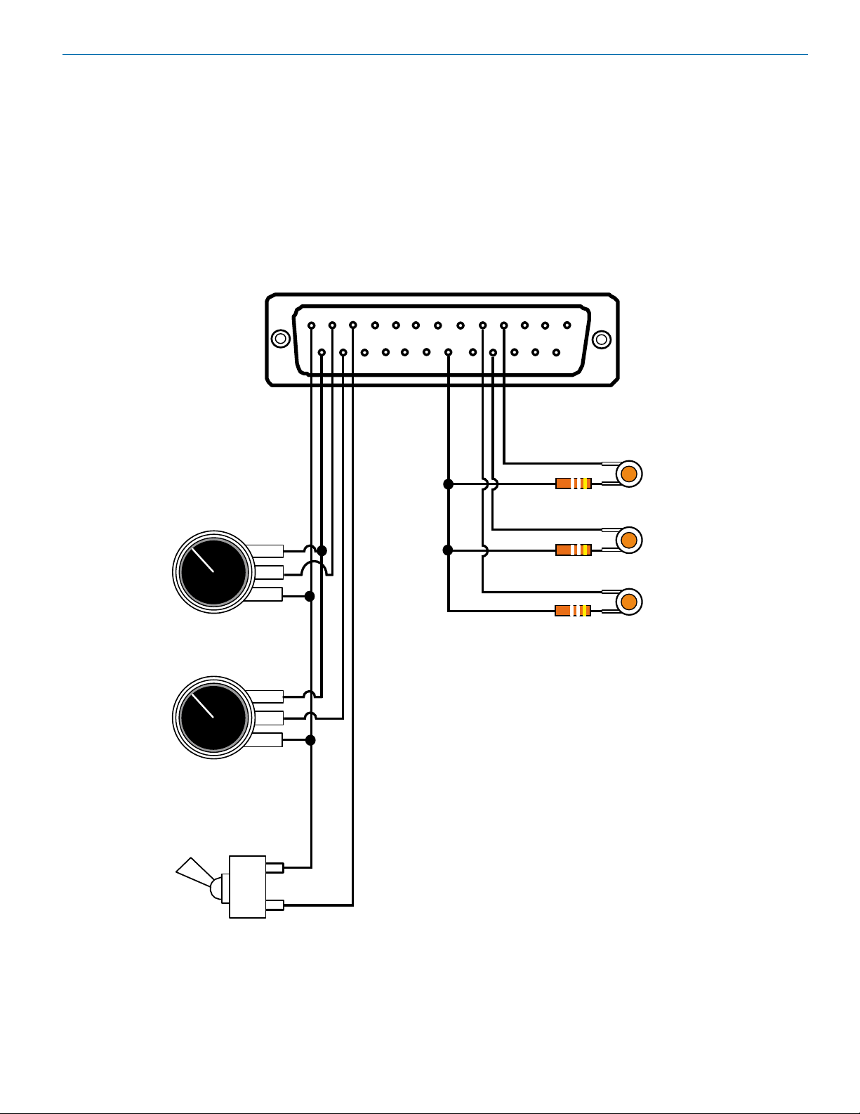
Programmable Inputs and Outputs Wiring
Remote control with external pots and switches is provided with Programmable Inputs on a standard DB-25 connector
on the rear panel. Programmable Outputs are used to provide external LED indicators and to trigger other events.
Examples of the wiring are shown below.
1 - GND
2 - IN 1
3 - IN 3
4 - IN 5
5 - IN 7
1
6 - IN 9
7 - IN 11
8 - GND
9 - OUT 1
10 - OUT 3
11- OUT 5
12 - OUT 7
13 - GND
14 - +5V
15 - IN 2
IN 1
Potentiometer
ccw cw
16 - IN 4
17 - IN 6
18 - IN 8
19 - IN 10
20 - +5V
21 - OUT 2
22 - OUT 4
23 - OUT 6
24 - OUT 8
25 +5V
13
LED
OUT 3
500 Ohms
LED
OUT 4
500 Ohms
LED
OUT 1
500 Ohms
IN 2
Potentiometer
IN 3
OFF
ON
* Windows Vista and XP or are trademarks of
ccw cw
Switch
Microsoft Corporation.
Rio Rancho, NM
Three Programmable Inputs:
2 - 10 K linear potentiometers
for volume control
1 - To bble switch for muting
3 Programmable Outputs:
LEDS for function indicators
(380 to 500 Ohm resistors in-line
to avoid burning out LEDS)
NOTE
Common Connections can be used for
all voltage and ground connections
among all devices.
9
Page 10

DMPA12 Installation Guide
Installing LecNet2 Software and USB Driver
The LecNet2 USB drivers are installed from the Installation Disk which comes with each processor by running
the LecNet2 Device Installer. Normally, this is done
before connecting a processor for the first time, however, it can done afterwards if necessary. The driver
installation only needs to be done once.
If a LecNet device is connected to a PC without prior
installation of the driver from the Installation Disk,
manual installation is possible in the cases of Windows
XP and Vista operating systems using the New Hard-
ware Found wizard. In the case of Windows 7, there is
no New Hardware Found wizard, so manual installation
is a bit more involved. In any of these cases, it’s not
really necessary - just cancel the New Hardware Found
wizard (if open) and run the LecNet2 Device Installer
from the Installation Disk.
Installation with LecNet2 Device Installer
Step 1
Place the LecNet2 Installation Disk into the CD-ROM
drive on the computer. If Auto Run is enabled on that
drive, the installation utility will open.
Step 2
The LecNet2 Device Installer opens:
Click Next to proceed
Step 3
The EULA is presented:
If AutoRun is not enabled, use Start>Run to run auto-
Run.exe on the drive holding the LecNet2 Installation
Disk.
If the CD-ROM drive is assigned as drive E: then type
E:\autoRun.exe in the window and press Enter to open
the LecNet2 utility.
With Windows Vista and 7 operating systems, click on
the Windows logo at the bottom left of the desktop, then
type E:\autoRun.exe into the search field just above
the Windows logo.
Two versions of the USB driver installer are provided for
different types of Windows PC:
• 32-bitWindows,clickonInstallUSBDrivers(32-bit)
• 63-bitWindows,clickonInstallUSBDrivers(64-bit)
Click on the option that is correct for your PC.
10
Accept, then click Next to proceed.
LECTROSONICS, INC.
Page 11

The drivers are installed from the CD. When installation
is complete, the final page of the installer will appear.
DMPA12 Installation Guide
Manual Installation
If the USB drivers have not been pre-installed on a PC
prior to connecting a LecNet2 device for the very first
time, you may install the manually if you wish.
On Windows XP and Vista operating systems, the
Found New Hardware Wizard will open when the device is detected. It will walk you through the process of
installing the LecNet2 drivers. To proceed, you will need
the LecNet2 Installation Disk. Click on the following link
and follow the instructions:
Windows XP USB driver manual installation guide
On Windows 7 operating systems, the system attempts
to find a driver automatically when the device is detected. If it cannot find one, it notifies the user that driver
installation failed. In this case, the Windows Device
Manager is used to install the drivers. To proceed, you
will need the LecNet2 Installation Disk. Follow these
instructions:
Windows 7 USB driver manual installation guide
The Driver Name and Status are displayed. Click on
Finish to close the installer. You may new connect any
LecNet2 device to the PC and drivers will be loaded
automatically.
Rio Rancho, NM
11
Page 12

DMPA12 Installation Guide
Control System Interconnections
In addition to a Windows® based computer system,
the DM84 can be controlled by external serial control
system using the RS-232 interface, such as those from
Crestron® and AMX®.
16: IN 4
6: IN 9
11: OUT 5
7: IN 11
12: OUT 7
8: GND
13: GND
9: OUT 1
14: +5V
10: OUT 3
15: IN 2
PROGRAMMABLE
INPUTS / OUTPUTS
USB
1: GND
13
2: IN 1
25
3: IN 3
4: IN 5
5: IN 7
1
14
LecNet 2
RS-232
RS-232 Port USB Port
Two RS-232 serial cables are provided.
The cable with the BLACK TRS connector is an RS232 cable wired for use with a laptop computer system.
Black cable for
computer connection
17: IN 6
18: IN 8
19: IN 10
20: +5V
21: OUT 2
22: OUT 4
23: OUT 6
24: OUT 8
25: +5V
Part# 21529-1 (Black Cable)
Device to PC
S
R
3.5MM
T
Stereo Plug
Wiring Diagram, 9 Pin D-Sub
LecNet Device Transmit
Tip
LecNet Device Receive
Ring
Gnd
Sleeve
LecNet Port
Wiring Diagram, 25 Pin D-Sub
LecNet Device Transmit
Tip
LecNet Device Receive
Ring
Gnd
Sleeve
LecNet Port
9 or 25 Pin Female
D-Subminiature
CD
N/C
RX
TX
DTR
Gnd
DSR
RTS
CTS
N/C
RI
RX
TX
Sig Gnd
Chassis Gnd
RTS
CTS
DSR
DTR
20
1
2
3
4
5
6
7
8
9
3
2
7
1
4
5
6
Host
Serial
Port
(PC)
Host
Serial
Port
(PC)
The cable with the RED TRS connector is designed
to be used with a control system such as those from
Crestron® or AMX®.
Red cable for AMX and
Crestron control systems
NOTE: Crestron® is a trademark of Crestron
Electronics, Inc. AMX
of AMX Corp.
®
is a registered trademark
Part# 21710-1 (Red Cable)
Device to AMX or Crestron
S
R
3.5MM
T
Stereo Plug
LecNet Device Transmit
Tip
LecNet Device Receive
Ring
Sleeve
Gnd
LecNet Port
N/C
N/C
N/C
N/C
N/C
N/C
9 Pin Female
D-Subminiature
1
RXD
2
3
TXD
4
5
Gnd
6
7
8
9
AMX
or
Crestron
Port
12
LECTROSONICS, INC.
Page 13
DMPA12 Installation Guide
Initial Setup
The initial setup of a DMPA12 system is a simple four
step process:
• SettheunittotheMaster mode, if necessary
• Connect the unit to the computer
• SelectthesignalSource
• SettheGain / Level
LecNet2™ Software and the USB Driver must be installed before these steps can be completed.
Master/Slave Configuration
IMPORTANT: When operated as a “stand
alone” unit, the amplifier must be configured
as a Master before it will communicate with a
computer for setup.
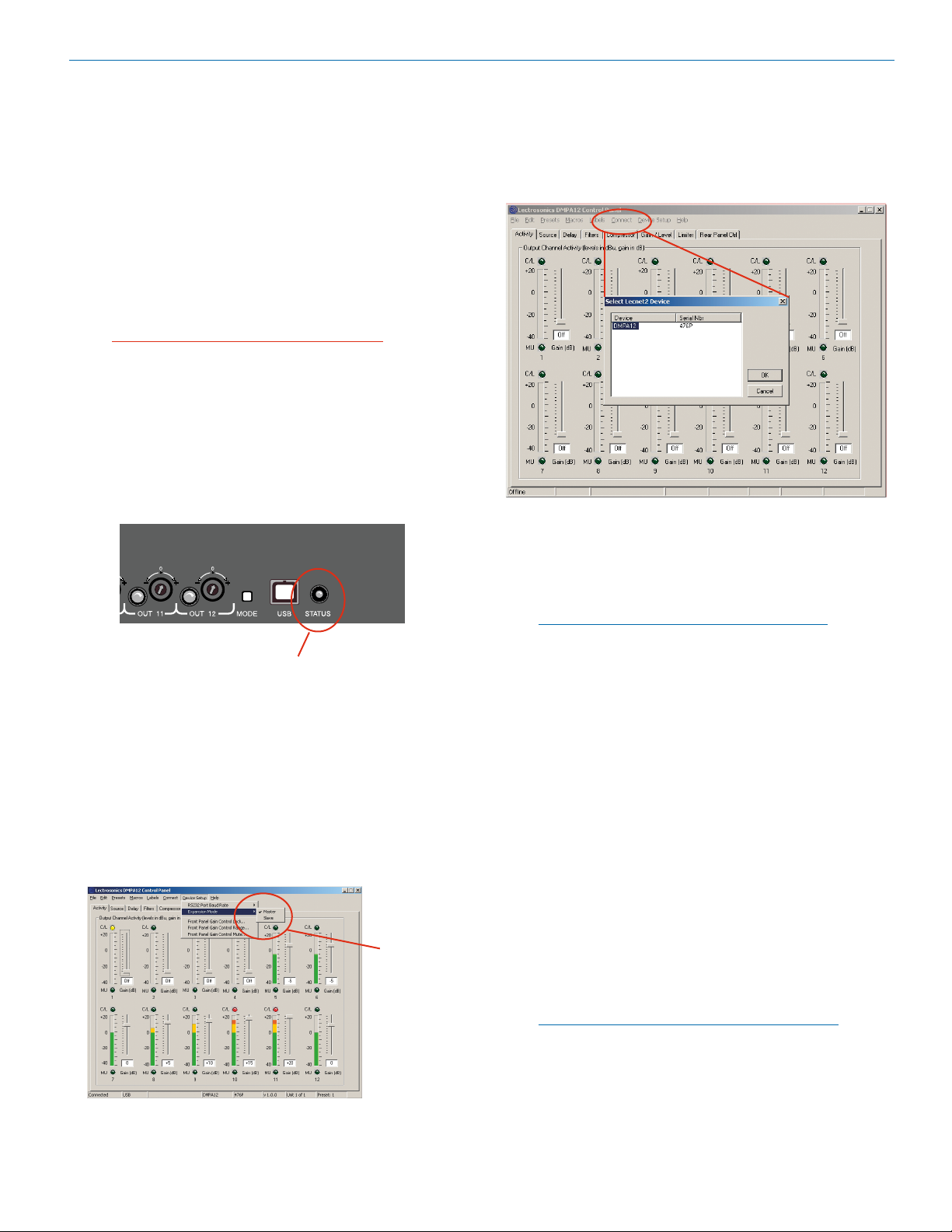
First, connect ONLY the computer and a power cable
to the processor. Turn the power on and observe the
Status LED on the front panel. If the LED is blinking, the
unit is in the Slave mode and cannot start up because it
does not detect the presence of a Master unit.
Connect
For simplicity, the instructions shown on this page
include only USB and RS-232 connections for setup
using a computer connected directly to the amplier. For
additional methods of connecting to the unit including
network and offline use, see page 17.
Connecting via a USB port.
The STATUS LED will blink if the
unit is turned on and in the Slave
mode and there is no DM Master
processor connected to it.
If the STATUS LED blinks at power up, press the MODE
button to reset the unit temporarily to the Master mode.
The unit can then be connected to a computer and
configured as needed for operation.
Permanent changes to the Master/Slave status must
be made with the GUI interface. The front panel MODE
button is temporary only.
Use the GUI
to make
permanent
changes to the
Master/Slave
status.
Connect the computer system to the DMPA12 unit using either the USB cable or the BLACK DB9 to stereo
mini (TRS 1/8”) cable for RS-232 communications.
(Both cables are included with the unit.)
NOTE: Only one DMPA12 unit at a time can be
connected to a serial port using the RS-232 cable.
Multiple units may be connected to a USB port
using a USB hub.
Turn the computer system on. After the boot sequence
is complete, click Start, then All Programs.
Select LecNet2, then select the DMPA12 control panel
from the list.
If the “Just a Reminder” dialog appears, click OK to
continue.
Click Connect on the Main Menu bar, then select the
type of connection between the computer system or
external control system and the DMPA12 unit.
USB - A standard interface that launches automatically
when the unit is connected and turned on. Front and
rear USB ports are provided.
Serial->COM1 - An RS-232 port for RS-232 communications between the DMPA12 and the computer
sytsem, or for connecting the DMPA12 to an external
Crestron® or AMX® control system.
Rio Rancho, NM
NOTE: The menu will list all serial ports detected
on the PC. However, many newer PCs have no
RS232 serial ports at all, so no serial connection
options will be listed.
For additional methods of connecting to the unit including network and offline use, see page 18.
13
Page 14

DMPA12 Installation Guide
Audio Final Mix and
Select the Signal Source
The input signal to the amplifier is taken from the DANI
(digital audio network interface) or from a tone or pink
noise source generated in the amplifier. It is useful to
use the tone or pink noise source during initial setup
to verify proper connections and signal routing to the
loudspeakers.
With a DM processor installed and microphones or
other audio sources are available, the sound system
can be operated during setup. The signals in the system
are delivered to the DMPA12 amplier via the DANI bus,
back propagating from the Master to the Slaves, and
forward propagating from Slaves to the Master. This
bi-drectional signal flow allows for a variety of configurations in the setup.
Matrix output sources
Tone and noise sources
There are also expansion buses that provide two additional sources for both the back and forward propagated
sources. These include “Exp” in the source name in the
pull down dialogue box.
The DMPA12 is usually positioned at the bottom of the
stack, configured as a Slave, with inputs coming from
the back propagated signals from the Master.
Audio Final Mix and
Data Back Propagation
Master
Slave
Slave
Slave
DMPA12 Slave
AB
TX
RX TX
EXPANSION
AB
TX
RX TX
EXPANSION
AB
TX
RX TX
EXPANSION
AB
TX
RX TX
EXPANSION
AB
TX
RX TX
EXPANSION
RX
RX
RX
RX
RX
Output Channels 1 - 12
This will provide Final Mixes 1 through 12, plus the two
Exp Final Mix signals from the Master unit.
Back propagated signals from the Master to the Slaves
on the DANI are labeled “Final Mix 1,” “Final Mix 2” and
so on. The term Final Mix refers to the mix at each output of the Master unit in the system.
Forward propagated signals moving upward from the
Slaves toward the Master are labeled “FP Main Mix 1,”
“FP Main Mix 2,” etc.
Data Back Propagation
Master
Slave
Slave
Slave
Slave
Audio Submix and
Data Forward Propagation
AB
RX
TX
RX TX
EXPANSION
AB
RX
TX
RX TX
EXPANSION
AB
RX
TX
RX TX
EXPANSION
AB
RX
TX
RX TX
EXPANSION
AB
RX
TX
RX TX
EXPANSION
NOTE: The DMPA12 must first be connected
directly to a computer to allow the signal sources
and levels to be set. This is mandatory to allow
signal flow through the unit, as the factory default
settings have no source selected and the outputs
are turned off.
If the system design utilizes 24 Final Mix signals at the
output of the Master, two DMPA12 amplifiers must be
positioned at the top of the stack, one as the Master
and the other as a Slave just below the Master.
AB
RX
DMPA12 Master
DMPA12 Slave
Slave
Slave
Slave
Slave
Slave
Audio Submix and
Data Forward Propagation
TX
RX TX
EXPANSION
AB
TX
RX TX
EXPANSION
AB
TX
RX TX
EXPANSION
AB
TX
RX TX
EXPANSION
AB
TX
RX TX
EXPANSION
AB
TX
RX TX
EXPANSION
AB
TX
RX TX
EXPANSION
Output Channels 1 - 12
RX
Output Channels 13 - 24
RX
RX
RX
RX
RX
In this configuration the Master and the Slave just below
it will have access to FP Main Mix signals 1 through 24,
plus the Exp bus signals, which will include all signals
from all slave units in the system.
14
LECTROSONICS, INC.
Page 15

DMPA12 Installation Guide
Adjust the Gain / Level
The default setting on the amplifier is OFF, so no signal
will be passed to the outputs until a value is selected.
Values can be entered directly into the field, or the values can be scrolled up and down with mouse clicks.
The multi-colored bar graphs indicate the signal levels
at the outputs. The LEDs indicate yellow for compression and red for limiting.
The Gain / Level tab is used to to adjust and monitor
the outputs. The GUI presents a multi-color bar graph
and LED for each of the 12 outputs.
About the Level Meter
The bar graph is a true RMS level meter which displays
the output audio level in dBu after digital signal processing is complete. The range of the meter is -40dBu to
+20dBu, referenced to the internal voltage scale prior
to digital to analog conversion and power amplification.
Note: The relationship between output level as indicated
on the level meter and power output into an 8 ohm load
is determined by these facts:
The maximum output of the digital to analog converter
(DAC) is 1 Vrms. So a full scale (+20 dBu) signal, after
digital to analog conversion, results in a 1 volt signal at
the input of the power amplifier.
The gain of the power amplifier stage is 20dB (for voltages, a tenfold increase).
So a 1 kHz test tone shown by the level meter to have
a level of +20 dBu (full scale) will result in in a power
output of 12.5 watts into an 8 ohm resistive load. This is
because the full scale signal, after conversion, results
in a 1 volt input to the power amplifier. Since it has a
gain of 20dB, the power amplifier output is 10 volts,
developed across the 8 ohm load. From “power equals
voltage squared divided by resistance” we get 100/8 or
12.5 watts. A +10 dBu test tone will result in 1.25 watts,
a 0 dBu test tone will result in 0.125 watts, and so on.
Note: These numbers are based on “ideal” components,
including the load resistance. Variations in real-world
components will result in measured power varying by as
much as 0.5dB from calculated figures.
Initial Setup Hints
1) The GUI interface is quite intuitive. As a recommended first step, we suggest you select Labels
from the Menu Bar and type in a description of each
output. This will simplify further setup steps because you will be able to easily keep track of which
output you are adjusting.
2) The right mouse click is handy in this interface by
allowing Copy, Paste, Delete, Undo and Select All
operations on the values presented in the fields.
3) Store startup settings in a startup default preset.
(See Storing and Recalling Presets in the online
HELP application.)
4) Presets will take about 3 seconds to switch due to
the many parameters in the unit - audio will switch
off temporarily during a preset switch to avoid feedback. If you need quicker response with no interruption to the audio, use macros instead - try using
the macro recorder for making any changes. The
only changes that cannot be made in a macro are
filter adjustments. such as EQ.
5) Store presets after changes are made and not before they are made.
6) Help is always available by clicking Help on the
Main Menu Bar. This Help is a comprehensive
resource and includes the latest revisions to the
software and firmware.
IMPORTANT: Any changes made during setup
must be saved in the unit via the preset menu.
For direct support from the factory, call 1-800-821-1121.
Ask for anyone in the SALES department. They will be
able to answer your setup and/or technical questions or
will get the correct person who can help on the phone.
Rio Rancho, NM
15
Page 16

DMPA12 Installation Guide
Additional Settings and
Functions
In many cases the installer is required to make additional settings and/or adjustments to enable functions such
as auxiliary remote controls using pots and switches.
Since some of these additional functions affect the basic signal flow and levels, it is important for the installer
to understand what is available and how some of the
most important processes work.
Compressor and Limiter
The Compressor and Limiter have individual tabs for
setup, but since these functions are so closely related
in operation, LEDs in the upper part of the GUI indicate
the real time status of each process on every channel.
Front Panel Gain Controls
The gain of input and output audio channels is adjustable from the front panel of the DMPA12. This feature is
useful for system setup and adjustment, and may be left
enabled to allow users to “touch up” gains as needed
during operation.
Any or all of the front panel gain controls may be
“locked out” to prevent unauthorized changes to the
system. This is done using the Control Panel GUI (in
Device Setup Menu) or LecNet2 serial commands.
Changes made to the gain control lock settings take
effect immediately and are global in scope - the
same settings are in effect no matter what memory
“preset” is loaded.
Compressor settings and parameters
Limiter settings and parameters
For a full explanation of these functions, refer the help
file included with the GUI or the Reference Manual
included on the supplied CD.
Front panel level controls can be locked out or enabled
with check boxes in a dialogue box under Device Setup.
Also under Device Setup are dialogue boxes to adjust
the range of the front panel control and a special option
that mutes the channel when the control is fully counter-clockwise. The minimum gain position has a special
meaning - the channel will be turned “off” when the control
is rotated to the fully counter-clockwise position.
NOTE: When the Front Panel Mute feature is
enabled, the minimum gain position has a special
meaning. The channel will be muted and the
associated activity indicator will blink RED to
warn the user that no audio is being passed. This
feature can be controlled using the supplied GUI
control panel or the serial command “fpmten.”
Gain can be increased or decreased within a range which
is centered around 0 dB (unity) gain. The range of adjustment for each channel is individually programmable using
the Control Panel GUI (in Device Setup Menu) or LecNet2
serial commands. Changes made to the gain range
settings take effect immediately and are global in
scope - the same settings are in effect no matter
what memory “preset” is loaded. The default range is
30 dB (+/- 15 dB).
16
LECTROSONICS, INC.
Page 17

Front Panel Output Activity Indicators
These indicators reflect activity on the output audio
channels. Useful for setup and troubleshooting, these
tri-color LEDs are interpreted as follows:
• DARKchannelisinactive
• GREENaudiopresent(levelgreaterthan-35dBu)
• ORANGEoutputcompressorisactive
• REDoutputisinlimiting
• BLINKINGREDoutputhasbeenmutedusingfront
panel gain control
• BLINKINGORANGEafaultexistsontheoutput
- check wiring for short circuits, etc.
Output Fault Indications
The outputs are protected from shorts and thermal
overload. When a fault exists, the output will shut down
and the front panel activity LED will blink orange. Faults
are automatically reset and the output restored when
the cause of the fault is removed.
Since the outputs are paired, sharing a common ground
connection, a fault on either output on the connector will
cause both outputs to shut down and indicate on the
front panel LEDs.
DMPA12 Installation Guide
Choose Device Setup->Expansion Mode from the Menu
Bar. A submenu of choices will open, with a check mark
next to the current value. Use the mouse to select the
desired expansion mode. The change will not take effect
until power is cycled on the DMPA12.
RS-232 Baud Rate Adjustment
The RS232 serial port on the DMPA12 is intended for
use with third party control systems. Since the serial
port capabilities of these systems varies, a means of
changing the baud rate of the RS232 port to match the
control system requirement is provided. This adjustment
affects only the RS232 port.
Expansion Mode Setup
When installed in a system of one or more DM series
automixers, the DMPA12 must be configured to operate
in Slave mode. However in Slave mode a Lecnet2 device cannot function as a standalone unit, unconnected
to a system containing a Master device. For this reason
the DMPA12 ships from the factory with the expansion mode set to Master so that it can be operated in a
standalone manner. In this configuration it will capable
of booting up normally so that it can be configured using the control panel program. Once configured, it will
need to be switched to Slave mode prior to installation
in the Lecnet2 system.
If inadvertently set to operate in Slave mode while being
operated in a standalone manner, the DMPA12 will fail
to boot up, so it is impossible to connect to it with the
control panel in order to reverse the change. Recovery
from this situation is simple. Pressing the recessed button on the front panel of the DMPA12 will temporarily
set the expansion mode to Master, allowing it to boot
up. At this point the DMPA12 can be set back to Master
mode using the control panel program if desired.
Expansion mode changes do not take effect until power
is cycled on the DMPA12.
Of course, once configured as a Slave and installed into
a system, the DMPA12 boots up normally since it detects the presence of the Master device in the Lecnet2
system.
Choose Device Setup->RS232 Port Baud Rate from the
Menu Bar. A submenu of baud rate choices will open,
with a check mark next to the current value. Use the
mouse to select the desired baud rate. The change will
take effect immediately.
Rio Rancho, NM
17
Page 18

DMPA12 Installation Guide
Connect Options
The DMPA12 can be connected to a computer via the
following methods:
USB - A standard interface that launches automatically
when the unit is connected and turned on. Front and
rear USB ports are provided.
RS-232 - For direct computer connecton with this
standard serial interface, or for use with a Crestron® or
AMX® control system.
Network - One or more amplifiers may be made connected via a network using a gateway server acting
as a middleman, receiving DMPA12 commands and
forwarding them to the connected amplifiers via the
USB ports.
Extron IPL T S interface - Extron Electronics offers network software/hardware interfaces to connect
DMPA12 amplifiers to a computer via a network and
RS-232 ports. The IPL interface functions as a gateway
server over a LAN by means of an Ethernet connecton.
These interfaces are available only from Extron Electronics.
Serial->COM1 - An RS-232 port for RS-232 communications between the DMPA12 and the computer
sytsem, or for connecting the DMPA12 to an external
Crestron® or AMX® control system.
NOTE: The menu will list all serial ports detected
on the PC. However, many newer PCs have no
RS232 serial ports at all, so no serial connection
options will be listed.
Go Offline - No connection is made. This mode can be
used for off line configuration and is the default mode.
18
LECTROSONICS, INC.
Page 19

DMPA12 Installation Guide
Rio Rancho, NM
19
Page 20

LIMITED ONE YEAR WARRANTY
The equipment is warranted for one year from date of purchase against defects in
materials or workmanship provided it was purchased from an authorized dealer. This
warranty does not cover equipment which has been abused or damaged by careless
handling or shipping. This warranty does not apply to used or demonstrator equipment.
Should any defect develop, Lectrosonics, Inc. will, at our option, repair or replace any
defective parts without charge for either parts or labor. If Lectrosonics, Inc. cannot
correct the defect in your equipment, it will be replaced at no charge with a similar new
item. Lectrosonics, Inc. will pay for the cost of returning your equipment to you.
This warranty applies only to items returned to Lectrosonics, Inc. or an authorized
dealer, shipping costs prepaid, within one year from the date of purchase.
This Limited Warranty is governed by the laws of the State of New Mexico. It states the
entire liablility of Lectrosonics Inc. and the entire remedy of the purchaser for any
breach of warranty as outlined above. NEITHER LECTROSONICS, INC. NOR
ANYONE INVOLVED IN THE PRODUCTION OR DELIVERY OF THE EQUIPMENT
SHALL BE LIABLE FOR ANY INDIRECT, SPECIAL, PUNITIVE, CONSEQUENTIAL,
OR INCIDENTAL DAMAGES ARISING OUT OF THE USE OR INABILITY TO USE
THIS EQUIPMENT EVEN IF LECTROSONICS, INC. HAS BEEN ADVISED OF THE
POSSIBILITY OF SUCH DAMAGES. IN NO EVENT SHALL THE LIABILITY OF
LECTROSONICS, INC. EXCEED THE PURCHASE PRICE OF ANY DEFECTIVE
EQUIPMENT.
This warranty gives you specific legal rights. You may have additional legal rights which
vary from state to state.
581 Laser Road NE • Rio Rancho, NM 87124 USA • www.lectrosonics.com
(505) 892-4501 • (800) 821-1121 • fax (505) 892-6243 • sales@lectrosonics.com
20 July 2011
 Loading...