

Page 1
DM84
Digital Matrix Processor
• 8-in/4-out digital matrix architecture in a stackable configuration
• Programmable front panel level controls with activity LEDs
• 6 filters, 6 feedback eliminators (ADFE), compressor and delay on each input
• 9 filters, delay and compressor/limiter on each output
• USB and RS-232 interfaces for setup and comprehensive remote control
• Balanced, floating differential inputs and outputs - no pin 1 problem
• Digital I/O ports for "daisy chaining" and to connect other LecNet 2 devices
• Proportional gain auto mixing algorithm with AutoSkew
TECHNICAL DATA
™
- US Patent 5,414,776
• 128 global macros, each with up to 64 commands, and 115 characters per command
The DM84 combines a stackable 8-in/4-out automatic
matrix mixer with a powerful DSP signal processing
package and extensive remote control capabilities for any
sound system application with multiple microphones and
loudspeakers. Multiple DM84 units can be stacked to
expand the matrix with unlimited inputs and up to 12
outputs. The unit also supports the full LecNet2 digital
matrix, so it can also be integrated with other DM Series
processors in 24 output systems.
The primary applications are in sound reinforcement and
recording in boardrooms, courtrooms, worship centers,
distance learning systems, hotels and other applications
that benefit from matrix signal routing, automatic mixing
and remote control options. Once setup is completed with
the supplied LecNet2 software, the unit runs as a standalone device. Front panel controls are provided to make
minor adjustments to the input and output levels, expanding its usefulness into stand-alone applications. The
adjustment range of each control is defined in the software setup to optimize it for various needs.
The DSP features include a full complement of filters,
ADFE (automatic digital feedback eliminators), compressors, limiters and delay on every channel to optimize the
signal processing needed for every application. This
processing is available at the inputs to compensate for
microphone placement and signal characteristics, or to
adjust for differences in tonal quality or dynamics of
various signal sources. Each output has individual filters
and a proprietary, adaptive time constant compressor/
limiter to feed recorders or power amplifiers.
Extensive control capability is built into the unit with an
intuitive command structure to allow external control with
USB or RS-232 connections. Touch panel control systems
easily integrate into the command structure. Remote
control, monitoring and setup can also be done via
ethernet connections using a low cost interface provided
by another manufacturer.
Up to 128 macros can be stored in internal memory. Each
macro can contain up to 64 commands, with 115 characters in each command. Macros can be invoked with serial
commands from touch panel control systems or contact
switches connected to the logic I/O ports on the rear
panel. The macros can be chained so that one macro can
call another one, which may call yet another one. In
addition, a built-in macro recorder greatly simplifies the
creation and use of macros.
The audio inputs and outputs are balanced, differential
circuits (no pin 1 problem) to eliminate noise from external RF and power sources, even with long cable runs.
The patented gain proportional automatic mixing algorithm* is applied at the crosspoints in the matrix so each
input can behave differently at each output. For example,
input 4 can be a microphone that participates in the NOM
attenuation applied by the auto mixing algorithm at some
of the ouputs, and operate as a direct signal for recording
at other outputs.
Rio Rancho, NM, USA
www.lectrosonics.com
Page 2
General Overview
The LecNet2 product group introduces a powerful series
of audio components and unique solutions for the design
and installation of sound systems with multiple microphones and loudspeakers. The DM84 is a very useful
member of this family in that it can satisfy cost conscious
applications in stand-alone operation, or function as a
building block to configure larger systems. It addresses
the full digital matrix of the DM Series so it can also be
used with other models to add additional inputs and
outputs. The range of the front panel level controls can be
configured to suit specific preferences.
Digital Matrix
The digital signal flow provides an expandable digital
matrix with no crosspoint limitations. Automatic mixing
takes place at the crosspoint in the matrix so that every
input can participate in every output group at a different
level and with a different auto mixing behavior to optimize
the channel behavior for specific purposes.
In addition, a DANI (Digital Audio Network Interface) bus
is provided so that the digital audio signals and data from
the master and slave units are connected in stacked
configurations in larger sound systems.
Automixer Cell
The Automixer Cell is the core of the matrix. It is where
level control for the automatic mixing algorithm, mixing
mode and crosspoint gain is applied using data gathered
from other channels and devices. In a stacked configuration, the cell receives data from the master unit above it
and from the slave units below it. The final mix is generated in the master unit and the data is returned back to
slave units to implement automatic mixing.
TxTxRx
Rx
Quad RJ -45 Conn
Output Volume Control Pots
Phan
In 1
On/Off
Phan
In 2
On/Off
Phan
In 3
On/Off
Phan
In 4
On/Off
Phan
In 5
On/Off
Phan
In 6
On/Off
Phan
In 7
On/Off
Phan
In 8
On/Off
Sync Audio Fr ame Sync
Digital
Audio
Network
Interface
(DANI)
Input Gain Control Pots
Prog
Prog
Prog
Prog
12 + 2 Submix + Mix Control
12 + 2 Mix + Mix Control
12 + 2 Mix + Mix Control
12 + 2 Submix + Mix Control
Prog I /O Conn
11
8
4
A/D Signal Pr ocessi ngProg
A/D Signal Pr ocessi ng
A/D Signal Pr ocessi ngProg
A/D Signal Pr ocessi ng
A/D Signal Pr ocessi ngProg
A/D Signal Pr ocessi ng
A/D Signal Pr ocessi ngProg
A/D Signal Pr ocessi ng
DB25
Prog I/O
Port
LecNet 2 C onn
1/8 '' Jack
8
RS-232
Port
Micro
12
Control ler
A/D
Control Signals
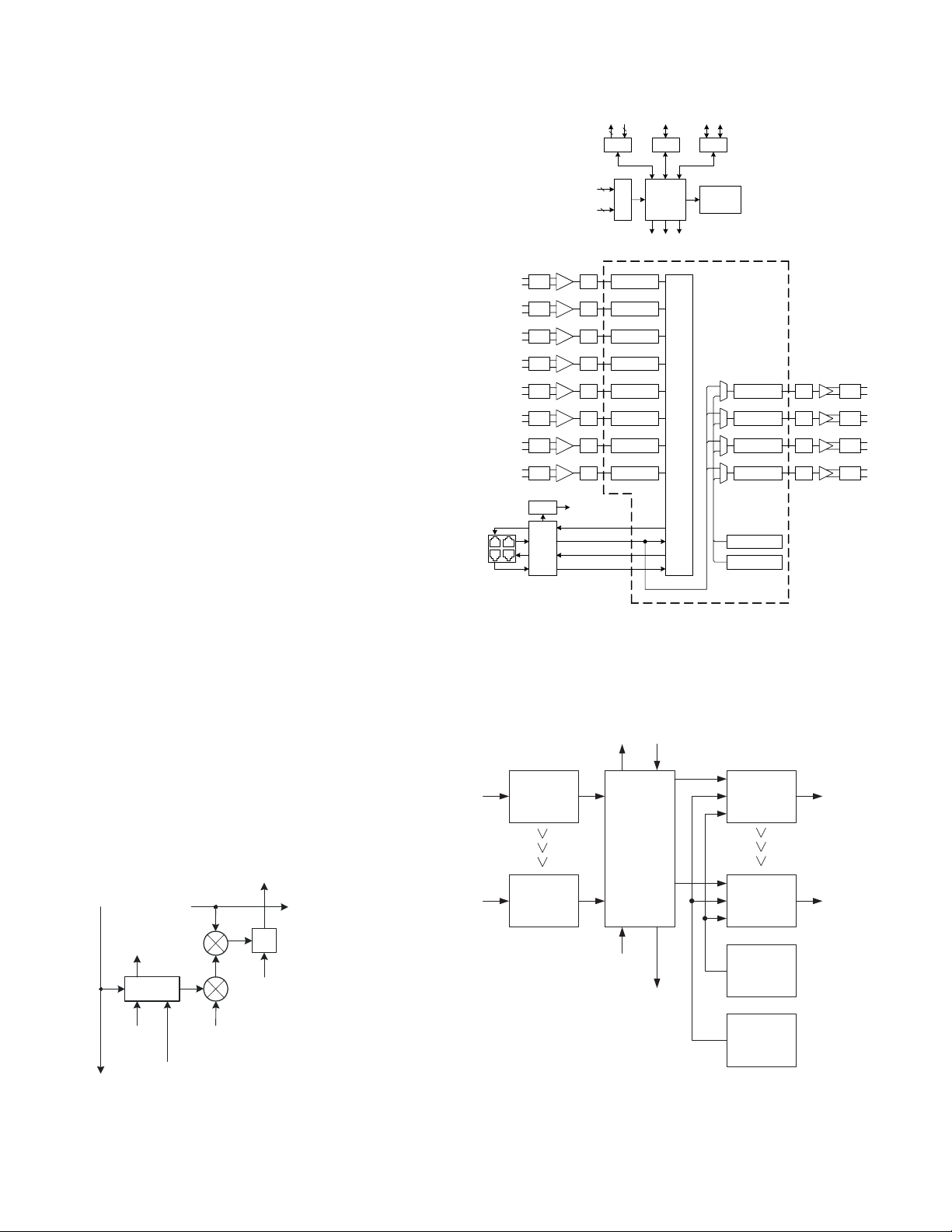
DM84 Functional Block Diagram
Front & Rear
USB B Conn
USB
Port
8 input 4 output
tric olor s ignal
indicat or LEDs
SHARC is a r egister ed tradem ark of
8 by 24 (+ 2) Automati c Mixing Matri x
Off: No signal
Green : Signal present
Orange : Compr essor/ lim iter active
Red: Cl ipping
Third Generation
®
DSP
SHARC
Analog Devices , Inc.
Signal Pr ocessi ng D/A
Signal Pr ocessi ng D/A
Signal Pr ocessi ng D/A
Signal Pr ocessi ng D/A
1 kH z Tone Gener ator
Pink N oise Gener etor
Out
Out 1
Atten
Out
Out 2
Atten
Out
Out 3
Atten
Out
Out 4
Atten
Power of the Mix
The Power of the Mix is the reference used to determine
the gain to be applied to each individual output channel.
In a multi-unit stacked configuration, this data is sent to
the slaves from the master unit.
Crosspoint Gain
Crosspoint Gain is the gain selected with the control
panel that determines the level at the output.
Submix
Power of the Mix
Digital Matrix Functional Block Diagram
(single crosspoint shown)
Audio Input
Power of the
Submix
Automixer
Cell
Power of the
Submix
Mixing Mode
- Auto
- Direct
- Override
- Background
- Phantom
Crosspoint Gain
-70 to 20 dB
1 dB steps
+
Submix
24 Output Submixes
2 Expansion Submixes
26 Automixing Aux. Data
Input #1
Processing
Input #8
Processing
24 Output Submixes
2 Expansion Submixes
26 Automixing Aux. Data
DM84 Signal Flow
2 Expansion Signals
Automixing Control Data
24 by 12+2
Automatic
Mixing
Matrix
2 Expansion Signals
Automixing Control Data
Output #1
Processing
Output #4
Processing
Tone
Generator
1 kHz, 0 dBu
Pink Noise
Generator
0 dBu
2
Page 3
Mixing Mode
The automatic mixing algorithm applies a patented gain
proportional algorithm (
#5,402,500
output to behave differently relative to the other inputs
assigned to the output.
Five different mixing modes are available:
) allowing each input assigned to a particular
Auto - In automatic mode the input applied to the
crosspoint is mixed into the output channel using
the the Adaptive Proportional Gain automixing
algorithm in the normal manner. This is the most
common setting.
Direct - In Direct mode the automixing algorithm is
bypassed.
Override - Override mode is selected when it is
required that the input applied to the crosspoint
always dominates the output channel when it
becomes active.
Background - Background mode is selected when
it is required that the input applied to the crosspoint
dominates the output channel only when all other
inputs are inactive.
Phantom - A special mode that allows an input to
participate in the auto mixing activity at one or more
crosspoints, but the audio signal is not delivered to
the output. In essence, the NOM mixing activity is
separated from the actual audio signal. This allows
NOM attenuation to take place between zones in a
mix-minus sound system design. It preserves the
discrete signal routing implemented in a mix-minus
sound reinforcement system that isolates microphones and loudspeakers.
US Patents #5,414,776
and
LecNet2 Software
Software is included with the DM84 and available for
download from the website at:
The software is used primarily for setup, with the configuration saved on file and into the unit's memory for actual
operation. Once configured, the DM84 runs without a
host computer.
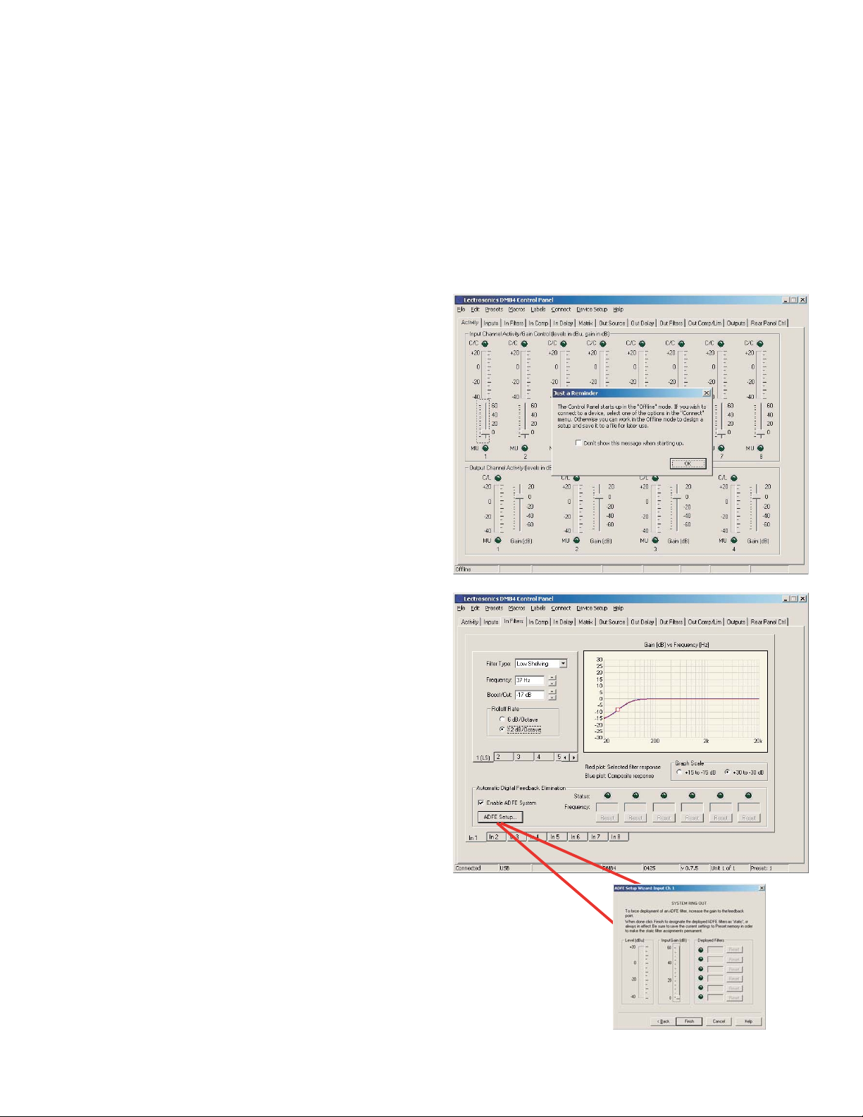
The software is user-friendly, with a variety of screens
provided for each section of the signal flow and system
design. The software runs under Windows
operating systems using a familiar tabbed layout. A few
sample screens are shown below.
www.lectrosonics.com
®
2000 and XP
.
*Windows is a registered trademark of Microsoft Corp.
3
Page 4

Input Processing
Each input channel provides individual stages for gain,
filtering and compression and delay.
Input Gain
The input applies software controllable gain with a level
indicator and clipping indicator.
Filters
Up to six filters can be implemented at each input to
idealize the signal equalization.
The filter types include:
Low pass
High pass
Band pass
Parametric EQ
Low shelving
High shelving
Filter slopes can be selected with 6 or 12 dB per octave
Butterworth or Bessel parameters. Multiple filters can be
assigned to create steeper slopes in 6 dB steps.
ADFE (automatic digital feedback eliminator)
Six narrowband notch filters are automatically placed on
ringing and/or oscillating frequencies to cancel acoustic
feedback. A pop-up screen provides a utility to manually
increase the gain in small increments to “ring out” the
sound system. As the ringing begins to occur the filters
are automatically placed. The filters can then be stored as
static filters in the presets.
Input Compressor
The compressor implementation is a unique “soft knee”
type based on an RMS level detector controlled by a
single time constant parameter. This is a new design
which responds to varying rates of change in the signal
level by dynamically adjusting the attack and release
times for best performance. Adjustment is simplified by
entering a single value (half of the desired release time).
The attack time is then applied by the DSP to vary with
the signal.
The default value is 100 ms, which sets the release time
at about 200 ms. The attack time is signal controlled and
varies from about 2 ms to about 100 ms as is needed to
handle the signal dynamics. See the reference manual
for a closer look at this unique and very effective compressor.
Compressor adjustment parameters include:
Threshold
Time Constant
Compression ratio
Makeup gain
Delay
The input delay can be set up to 100 ms in .50 ms
increments. The delay can also be set according to
distance in either feet or meters.
Indicator
Clipping
Detector
A/D
Coarse Gain
0 to 50 dB,
10 dB steps
Input Gain & Polarity
-10 to +60 dB
1 dB steps
Fine Gain & Polarity
-10 to 10 dB,
1 dB steps
0 - 100 ms
0.5 ms steps
Typical Input Signal Processing Blocks
Delay
Six Filter
Stages
Off, LP, HP, BP,
PEQ, LS, HS
6 or 12 dB/oct.
Butterworth or Bessel
when applicable
Gain Reduction Indicator
Six ADFE
Filters
Enable/Disable
Activity Indicator
Compressor
Threshold
Time Constant
Ratio
Makeup Gain
Indicator
Level Meter
4
Page 5

Output Processing
Output Source Select
In normal operation the digital matrix delivers the audio
signals to the outputs, which consist of the final mixes
backpropagated from the master unit in the system via
the Digital Audio Network Interface (DANI), with 12 mixes
from the main matrix and 2 mixes from the expansion
matrix. Internal pink noise and 1 kHz tone generators are
also available at each output for diagnostics, setup and
sound masking purposes.
Output Gain and Level Indicator
The output level can be adjusted from - 70 dBu to +20
dBu in 1 dB steps to perfectly match the requirements of
the device being fed by the channel. A bar graph is
provided by the on screen GUI to accurately indicate the
output level as it operates and is adjusted.
Delay
A delay of up to 250 ms in .50 ms increments is provided
at each output. The delay can also be set according to
distance in either feet or meters.
Filters
Up to nine filters can be implemented at each output to
idealize the signal equalization:
Low pass
High pass
Band pass
Parametric EQ
Low shelving
High shelving
Filter slopes can be selected with 6 or 12 dB per octave
Butterworth or Bessel parameters. Multiple filters can be
assigned with the same values to to creater steeper
slopes in 6 dB steps.
Gain Reduction Indicator
Output Compressor and Limiter
A versatile compressor and limiter are provided at each
output to control the average level and dynamics of the
audio signal, and restrict the maximum output level to
optimize the channel for its purpose. Compression is
often needed when the channel is feeding a recorder, and
limiting is often used to protect a loudspeaker system and
reduce distortion and amplifier overload.
The compressor implementation is a unique “soft knee”
type based on an RMS level detector controlled by a
single time constant parameter. This is a new design
which responds to varying rates of change in the signal
level by dynamically adjusting the attack and release
times for best performance. Adjustment is simplified by
entering a single value (half of the desired release time).
The attack time is then applied by the DSP to vary with
the signal.
The default value is 100 ms, which sets the release time
at about 200 ms. The attack time is signal controlled and
varies from about 2 ms to about 100 ms as is needed to
handle the signal dynamics. See the reference manual
for a closer look at this unique and very effective compressor.
Compressor adjustment parameters include:
Threshold
Time Constant
Compression ratio
Makeup gain
Limiter adjustment parameters include:
Threshold
Time Constant
Indicator
Activity Indicator
Activity Indicator
Level Meter
Delay Compressor Limiter
0 - 250 ms
0.5 ms steps
Typical Output Signal Processing Blocks
Nine Filter
Stages
Off, LP, HP, BP,
PEQ, LS, HS
6 or 12 dB/oct.
Butterworth or Bessel
when applicable
Threshold
Time Constant
Ratio
Makeup Gain
Threshold
Time Constant
Output Gain
-70 - +20 dB
1 dB steps
5
Page 6

The DANI Bus and Back Propagation
The core of the DM Series processors consists of a digital
matrix and a digital bus called DANI (digital audio network
interface). The digital matrix is common to all units in a
system. The DANI bus interconnects the hardware to
allow access to the matrix signal flow and transfer data
required for automatic mixing functions. In order to
understand the power and functions available with this
architecture it is helpful to think of them as entities
separate from the hardware.
In this sense a DM processor is simply a hardware-based
tap into the digital matrix via the DANI bus to interface
various types of microphones and audio equipment with
the digital matrix. Thus connected, the processors
distribute audio signals and share information about each
input and output to provide a myriad of features and
functions.
When multiple DM processors are stacked, each unit
participates with the digital structure in several ways:
• Delivering audio signals from its input terminals into
the forward-propagated submix bus
• Passing back-propagated final mix signals from the
unit above it to the next unit below it
• Applying gain and signal processing to the audio
signals at its input terminals
• Delivering audio signals to its output terminals as
selected by the setup
• Applying signal processing to the signals routed to
its output terminals
• Receiving and transmitting data required for the
automatic mixing process in the matrix
The digital matrix is common to all processors in the
stack, with automatic mixing taking place at the
crosspoints in the digital matrix. The output of each
crosspoint is then available at a variety of output terminals
on various processors in the stack.
Different processor models interface with the digital matrix
in different manners. Audio signals and data are propagated from the Slaves to the Master unit in a stack, then
the data and some of the final mix signals in the Master
are back propagated to the Slaves. This provides additional final mix outputs at the output terminals on the
Slave units.
DM Series
Slave
Slave
Processor
DM Series
Processor
DM Series
Processor
Master
Automatic Mixing Matrix
MASTER
SLAVE
Audio Submix
and Data
Forward Propagation
Audio Submix
and Data
Forward Propagation
Audio Final Mix
and Data
Back Propagation
Audio Final Mix
and Data
Back Propagation
SLAVE
6
Page 7

Hardware Control
The DM84 processor has programmable inputs which can
be used to control a wide variety of functions. Depending
on the function assigned to them, these programmable
inputs may be connected to momentary contact switches,
toggle switches, or potentiometers. When used with a
switch, the inputs are activated by by connecting them to
ground through the switch contacts, called a “contact
closure.” When used with a variable resistor, the inputs
respond to the applied voltage in the range 0 to 5 VDC.
Another feature of the rear panel control interface are a
set of programmable outputs which can be set up to
indicate either audio input channel activity or programmable input status. Programmable outputs act as an
electronic “contact closure” to ground. When the output is
active, the contact is closed (conducting to ground).
When the output is inactive, the contact is open (not
conducting to ground).
An important application of the rear panel control interface is to manage what is called the rear panel gain for
input and output audio channels. This is an additional gain
value that is added to the “main” gain value for a channel
to give the total gain applied. Rear panel gain is limited to
the range -60dB to 0dB, and therefore is actually intended
to function as a variable attenuator for the audio channel.
The purpose is to allow some amount of gain or level
control by the end user in a safe manner, using one of the
programmable inputs.
A typical application of rear panel gain is to allow adjustment of the level of an audio output (driving a speaker)
downward from some maximum by means of turning a
potentiometer connected to a programmable input which
has been set up to use the Analog Output RP Gain
Control function.
Complete details on the use of Rear Panel control is
provided in the Installation Guide and in the Control Panel
GUI provided with the unit.
Command Language
A very powerful, yet intuitive command language allows
complete control over DM Series processors with short
commands delivered via the USB or RS-232 ports. The
language and structure makes programming remote
control functions very easy. Individual function settings
and signal routing can be customized for a particular
application during setup, recalled from various screens
during operation, or recalled by other brands of remote
control systems. The RS-232 serial port is completely
compatible with control systems from AMX®, Crestron
and with Extron® IPL Series ethernet adapters which
allow remote control via standard networks. A complete
library and explanation of the commands and the command structure is available in the DM84 Reference
Manual.
®
Macros
A comprehensive macro utility greatly expands the
remote control capability. The DM84 can be remotely
controlled using commands sent over USB, a serial port,
or a network connection. An extensive text-based command language is defined for the DM84. Touch panel
controllers, for instance, use this command interface.
Macros are predefined groups of commands that are
stored internally by the DM84. All of the commands
contained in the macro can then be executed by issuing a
single Run command to the DM84. There are two advantages to this approach:
• Efficiency - only one command needs to be sent to
the DM to execute complex actions, which may
involve dozens of individual commands.
• Modularity - frequently executed sequences can be
implemented as a macro which can be reused in
other control designs, or combined with other macros
to form complex actions.
Up to 128 macros can be stored in the DM84 nonvolatile
memory. Macros are global in scope, meaning that they
are not associated with any particular preset. Each macro
can contain up to 64 commands, with 115 characters in
each command. Macros may be given a descriptive title
which is stored along with the command list.
Macros can be chained if necessary, meaning that one
macro can call another macro by virtue of containing a
run command. A run command issued from within a
macro will be delayed until after the first macro has
finished running. In other words, macros aren’t nested,
they always run sequentially (chaining). The best practice
when chaining macros is to make the run command the
last command in a macro.
The control panel contains a Macro Editor which is used
to create new macros or edit existing ones when the PC
is connected to a DM. Macros may also be opened and
saved as files, making it possible to work with them in
offline mode as well.
The control panel also contains a Macro Recorder which
allows a sequence of commands to be captured as a
macro without typing them into the Macro Editor. The
Macro Recorder works by capturing the commands
generated by the control panel when the mouse and
keyboard are used to make changes to the DM84 settings. The macro recorder can run be while connected to
a DM or used in offline mode to create command sets in
advance of the installation.
AMX, Crestron and Extron are registered trademarks of the
respective companies.
7
Page 8

Front Panel
The DM84 is housed in a single space 19” rack mount
assembly. The front panel provides input and output level
controls to make adjustments manually while the system
is operating. Multi-color LEDs indicate activity on each
input and output channel. A Mode switch allows booting
the unit as a Master when it is configured as a Slave and
powered up by itself.
Rear Panel
LecNet 2
A universal 100-240 VAC power supply with a standard
AC receptacle is provided on the rear panel. The USB and
RS-232 jacks are used for computerized setup, firmware
updates and to control systems during operation. Logic
input and output connections are made via a DB-25 jack.
Specifications
Audio inputs
Gain: -10 dB to +60 dB; programmable 1 dB steps
Input impedance: 2.5 k Ohm
Phantom voltage:15V, programmable
Connector: 5-pin Phoenix
Audio outputs: Floating balanced, either side can be grounded
Nominal level: 0 dBu all outputs, -40 dBu selectable on
outputs 9 through 12
Output impedance:
•450 Ohm differential programmable outputs at line level
•5 Ohm differential programmable outputs at microphone level
Input Dynamic Range: 96 dB at -50 dBu input level; 102 dB at all
other levels (unweighted 20 - 20 kHz)
Output Dynamic Range: 105 dB (unweighted 20 - 20 kHz)
Audio Performance:
IMD + noise: 0.1% max.
0.02% nominal input level
THD + noise: 0.1% (worst case)
0.02% nominal input level
EIN: -126 dBu
The Status LED indicates steadily in normal operation
and blinks in the presence of several different errors. A
USB port on the front panel allows easy access for setup
or troubleshooting from the front side of the rack. The
power switch is a rocker type with positive action.
RJ-45 jacks interface with other DM Series components
via the DANI bus. The balanced differential inputs and
outputs are paired on standard depluggable connectors
sharing a ground to reduce the amount of wiring needed.
Connectors:
Audio I/O: 5-pin Phoenix
Expansion: RJ45
Logic I/O: DB25
Serial: Standard USB and mini TRS
Digital Audio Network Interface ( DANI):
Physical level: LVDS (Low Voltage DIfferential Signal)
high speed
Connector: Four RJ-45
Cable quality: Shielded CAT-5
Transmission speed: 50 Mbits/s
Programmable control inputs
Number of inputs: 11
Analog voltage range: 0-5V
Logic input: TTL, LVTTL, CMOS, LVCMOS
Programmable control outputs
Number of logic outputs: 8
Logic control: Active low
Max sink current: 100 mA
Max supply voltage: 40 V
Supply voltage for control I/O: 5 V
Max current: 750 mA
Power requirements: 100-240 VAC, 47-63 Hz
Power consumption: 15 Watts
581 Laser Road NE • Rio Rancho, NM 87124 USA • www.lectrosonics.com
(505) 892-4501 • (800) 821-1121 • fax (505) 892-6243 • sales@lectrosonics.com
DM84TD - 20 July 2006
 Loading...