

Page 1
DHu
Digital Handheld Transmitter
INSTRUCTION MANUAL
Rio Rancho, NM, USA
www.lectrosonics.com
Page 2

DHu
Table of Contents
General Technical Description ........................................... 3
Microphone Capsules: ........................................................4
Mechanical Assembly .........................................................4
Battery Installation .............................................................. 5
Control Panel .......................................................................5
Setup and Adjustments ...................................................... 6
Powering On ...................................................................... 6
Powering Off ...................................................................... 6
Standby Mode .................................................................... 6
Power Menu ....................................................................... 6
Navigating Menus and Screens ......................................... 7
Menu Map ............................................................................. 7
Input Gain Adjustment ........................................................ 10
Programmable Switch Functions ....................................... 10
Parts and Accessories ........................................................ 12
Mic Capsule Adjustments ................................................... 13
(EXPERT LEVEL ADJUSTMENT) ..................................... 13
Specifications ...................................................................... 14
Wireless Designer Software .............................................. 14
Firmware Update Instructions ............................................ 14
Troubleshooting ................................................................... 15
Service and Repair .............................................................. 17
Returning Units for Repair ................................................. 17
2
LECTROSONICS, INC.
Page 3

General Technical Description
Digital Hand Held Transmitter
Introduction
The transmitter benefits from a fourth generation
design with specially developed, high efficiency digital
circuitry for extended operating time on two AA batteries. The transmitter can tune across the UHF television
band from 470.100 to 607.950 MHz, with a selectable
output power of 25 or 50 mW. The pure digital architecture enables AES 256-CTR encryption for applications
that require high level security.
Input Gain Range and Limiter
45 dB range of input gain adjustment allows gain
settings to accurately match the user’s voice and the
varying sensitivity of different microphone capsules. A
DSP-controlled analog audio limiter is employed before the A-D converter. The limiter has a range of more
than 30 dB for excellent overload protection. A dual release envelope makes the limiter acoustically transparent while maintaining low distortion. It can be thought
of as two limiters in series, a fast attack and release
limiter followed by a slow attack and release limiter.
The limiter recovers quickly from brief transients, with
no audible side effects, and also recovers slowly from
sustained high levels to keep audio distortion low while
preserving short term dynamics.
Frequency Selection
Operating frequency is normally selected using a
receiver or analyzer to assess signals in the local environment to avoid interference. Once an interferencefree frequency is identified, the transmitter frequency is
set to match the receiver.
The LCD on the transmitter displays frequency in MHz
and with a two character hex code that is used on
most Lectrosonics receivers.
Antenna
A unique helical antenna allows the transmitter to be
held in any position, since the user’s hands have little
or no effect on the RF output power.
Microphone Capsules
The transmitter is available from Lectrosonics with
the HHC and HHVMC cardioid condenser capsules.
Capsules from several other manufacturers are also
available for use with the HH: those with a 1.25” x 28
thread pitch and three contact rings. Condenser or
dynamic microphone capsules can be used to suit the
user’s preference or the application.
Encryption
When transmitting audio, there are situations where
privacy is essential, such as during professional
sporting events, in court rooms or private meetings.
For instances where your audio transmission needs
to be kept secure, without sacrificing audio quality,
Lectrosonics introduces Encryption Keys. Truly entropic encryption keys are first created by a Lectrosonics
receiver, such as the DSQD Receiver. The key is then
synced with the DHu via the IR port. The audio will
be encrypted and can only be listened to if both DHu
and receiver have the matching encryption key. If you
are trying to transmit an audio signal and keys do not
match, all that will be heard is silence or white noise.
IR (infrared) Sync
An IR Sync Port is used for quick setup with receivers
that offer this feature. Settings for frequency, step size
and compatibility mode are transferred from receiver to
transmitter via the IR ports.
Side Button Functions
A programmable switch on the side of the housing can
be configured as a mute/cough switch, a power switch
or be disabled.
USB Port for Key Transfer and Firmware Updates
The encryption key is generated in the receiver, then
transferred to the transmitter via a USB port using a
cable. This requires that the user be in direct contact
with both units, which increases the security level.
Firmware updates are enabled by simply downloading
a file and utility program from the Lectrosonics web
site, connecting the transmitter to a computer via the
USB port and running the program.
Rio Rancho, NM
3
Page 4
DHu
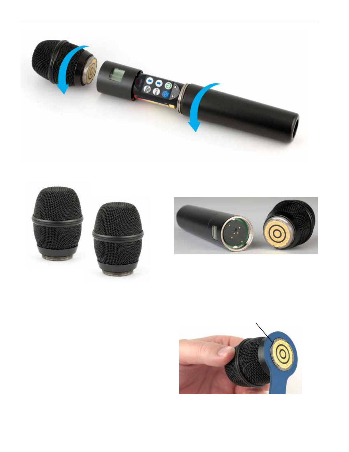
A mic capsule is
threaded onto the body
of the transmitter in the
direction shown.
Do not overtighten it.
The threaded interface is a 1.25”
diameter opening with 28 threads
per inch and three contact rings
Microphone Capsules:
Lectrosonics offers two types of capsules. The HHC is
the standard capsule and the HHVMC is the Variable
Mic Capsule which includes adjustments for Bass,
Midrange and Treble.
Mechanical Assembly
The lower housing opens by rotating
it in the direction shown. After the
threads are disengaged, pull the
housing downward until it engages
the detent that holds it open.
Do not touch the contacts between the mic capsule
and transmitter body. When necessary, the contacts
can be cleaned with a cotton swab and alcohol.
HHC Lectrosonics
cardioid electret
HHVMC Lectrosonics cardioid
electret with VariMic preamp
Along with these two models from Lectrosonics, a
variety of different capsules with a common thread
and electrical interface are available from the major
microphone manufacturers.
A list of compatible capsules is on the website at www.
lectrosonics.com listed the DHu product page.
*All product names are trademarks of their respective
owners, which are in no way affiliated with Lectrosonics.
Capsule Installation
Capsules are attached with a right-hand thread.
To remove the windscreen from the mic capsule,
line up the blue wrench (included with the capsule
head) with the flat notches on the lower threaded area
of the mic capsule.
Align flats on the wrench with flats on the capsule.
4
LECTROSONICS, INC.
Page 5
Digital Hand Held Transmitter
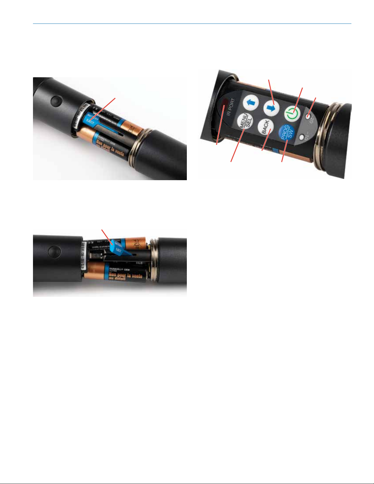
Battery Installation
To insert batteries, close the eject lever and insert the
upper contacts first (closest to the mic capsule). Polarity is marked on the label in the bottom of the battery
compartment.
Close
eject lever
to install
batteries
The contacts are very tight to prevent the batteries
from “rattling” as the transmitter is being handled. Pull
the eject lever outward to remove the batteries. The
battery tips will move outward, making them easier to
grasp.
Control Panel
Six membrane switches on the control panel are used
to set up the transmitter by navigating the menus on
the LCD and selecting the desired values.
IR Sync Port
Enter Menu and
Select Item
UP/DOWN Buttons for
Menu Item Selection
Power Button
Modulation
LEDs
Previous
Screen
Programmable switch
setup button
Pull eject lever outward to release batteries from contacts
Rio Rancho, NM
5
Page 6
DHu
Setup and Adjustments
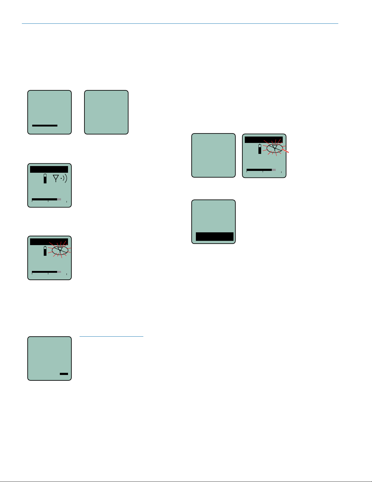
Powering On
Press and hold the Power Button until a status bar on
the LCD is completed. The status bar will appear on
the LCD, followed by a display of the model, firmware
version, frequency band and compatibility mode.
Hold
for
DHu
V1.01
Rf On
When you release the button, the unit will be operational with the RF output turned ON and the Main
Window displayed.
DHu
The Main Window
RF output ON
545.400
-40
-20
0
If you release the button before the countdown is complete, the unit will turn on in the Standby mode with the
RF output turned OFF and the antenna icon will blink.
DHu
The Main Window
545.400
-40
-20
RF output OFF
0
Powering Off
Press and hold the Power Button (or the side button if
it is configured for turning the power on and off) while
the status bar on the LCD is completed. The power will
then be turned off. This can be done from any menu or
screen.
Powering
O . . .
NOTE: If the Power Button
is released before the
countdown is completed, the
unit will remain turned on
and the LCD will return to the
same screen or menu that
was displayed previously.
Standby Mode
A brief push of the keypad Power Button turns the unit
on and places it into a “standby” mode (not transmitting). Press the button and release before the status
bar completes. This allows the transmitter to be set up
without the risk of creating interference for other wireless systems that are operating in the vicinity.
A notice will appear briefly confirming that the RF output of the transmitter is turned off, followed by the Main
Window. The antenna symbol will blink as a reminder
that the RF output is turned off.
DHu
Rf
Off
545.400
-40
-20
Symbol blinks
when RF output
is turned OFF
0
Power Menu
When the transmitter is turned on, a
Resume
Pwr Off
Rf On?
Backlit
one of the menu items, then press the MENU/SEL button to confirm this action.
• Resume: Continue operating in the same condition as before.
• Pwr Off: Turns off the transmitter.
• Rf On?: Begin transmitting the RF signal, enters
another screen prompting a Yes or No answer.
• Backlit: The LCD includes a backlight that illuminates the display for easier viewing. It is set to
come on when any button on the control panel is
pressed, then stay on for 5 seconds, 30 seconds
or stay on all the time.
• About: Displays the model, firmware version,
frequency block and compatibility mode.
The unit can also be turned off from any menu or
screen on the LCD by holding the power button in
while the status bar on the LCD is completed.
brief push of the Power Button on
the keypad will reveal a menu
allowing you to choose between
Resume, Pwr Off, Rf On?, Backlit
and About.
Use the UP/DOWN buttons to select
6
LECTROSONICS, INC.
Page 7

Digital Hand Held Transmitter
Use arrow buttons
Battery Condition
An icon on the Main Window indicates the approximate
remaining power of the batteries. This battery gauge is
most accurate with the typical voltage drop across the
life of alkaline batteries.
DHu
545.400
-40
-20
Rechargeable batteries give little or no warning when
nearing depletion. If you use rechargeable batteries
in the transmitter, we recommend trying fully charged
batteries first, noting the length of time that the batteries will run the unit, and in the future using somewhat
less than that time to determine when the battery
needs to be replaced. The Venue and other receivers
from Lectrosonics offer a timer function to assist in this
process.
Battery Gauge
0
Navigating Menus and Screens
The Main Window displays the following information:
Function of the
programmable
switch
Operating
frequency in MHz
Audio level
1) Press the MENU/SEL button to enter the setup
menu. Use the UP/DOWN buttons to highlight the
menu item.
2) Press the MENU/SEL button to enter the setup
screen for that item. Use the UP/DOWN buttons
to select the desired value or mode.
Gain
Freq.
ProgSw
Rolloff
DHu
MUTE
545.400
-40
-20
Gain
-40
Icon indicates
whether RF output
is turned on or off
Battery condition
0
25
-20
0
Menu Map
Gain
Freq.
ProgSw
Rolloff
Phase
BatType
TxPower
Default
KeyType
WipeKey
SendKey
SEL
SEL
SEL
SEL
SEL
SEL
SEL
SEL
SEL
SEL
SEL
BACK
BACK
BACK
BACK
BACK
BACK
BACK
BACK
BACK
BACK
BACK
Gain
-40
-20
Freq.
470.675
No Grp
ProgSw
Power
Rolloff
50 Hz
Phase
Normal
Invert
BatType
Alk.
Lith.
TxPower
25 mW
50 mW
Default
Settings
No
Yes
KeyType
Standard
WipeKey?
No
Yes
SendKey
Share:
22
to select value
Level meter at bottom of screen
0
Press to highlight MHz or kHz
Select value with arrow buttons
Select option with arrow buttons
Select value with arrow buttons
Select option with arrow buttons
Select option with arrow buttons
Select option with arrow buttons
Select option with arrow buttons
Select option with arrow buttons
Select option with arrow buttons
MENU
Press to send key
SEL
3) Press the MENU/SEL button to save this setting
and return to the previous screen.
4) Press the BACK button to return to the Main
Window.
Rio Rancho, NM
7
Page 8

DHu
Gain
This setting is very important since it can have a significant effect on the signal to noise ratio the system
will deliver. The gain adjustment can even affect the
operating range of the wireless system. Gain must be
set according to the individual voice, the mic capsule
in use and the handling technique of the user. LEDs in
the control panel facilitate accurate gain adjustment.
Gain
Freq.
Gain
25
ProgSw
Rolloff
IMPORTANT: See the section Input Gain
Adjustment on page 9 for details.
-40
-20
0
Freq.
The operating frequency is normally determined using
the scanning function in the receiver or with coordination software. The frequency is shown on the transmitter LCD display in MHz and with a hexadecimal code
that is used on most Lectrosonics receivers.
Frequency groups are also able to be received via IR
(Inrared) port sync. The group options are set by the
receiver, and will show at the bottom of the screen as
No Grp, Grp x, Grp w, Grp v, or Grp u.
Use the MENU/SEL button to toggle between options
and UP and DOWN arrows to adjust.
Gain
Freq.
ProgSw
Rolloff
Freq
628.200
Grp x
Frequency
Frequency
Group
Rolloff
A low frequency roll-off filter can be set for a -3dB point
at 25, 35, 50, 70, 100, 120 or 150 Hz. Roll-off slopes
are 12.2 dB/octave at 35 Hz and 10.1 dB/octave at 70
Hz through 125 Hz.
Gain
Rolloff
Freq.
ProgSw
70 Hz
Rolloff
The roll-off frequency is normally adjusted by ear to
suit personal preferences.
Phase
The phase (polarity) of the audio can be inverted to
match other microphone capsules as needed.
Freq.
Phase
ProgSw
Rolloff
Phase
Normal
Invert
BatType
Selects the type of batteries being used; alkaline or
lithium.
Phase
BatType
TxPower
Default
BatType
Alk.
Lith.
ProgSw
The Programmable Switch on the housing can be set
to provide several functions, or it can be bypassed.
NOTE: See section on Programmable Switch
Functions.
Gain
Freq.
ProgSw
Rolloff
8
Functions:
(none)
Mute
Power
TalkBk
Cough
PTT
TxPower
Output power can be set to 100 mW to extend operating range (which can also suppress noise and dropouts to some extent) or set to 50 mW to slightly extend
the operating life of the batteries.
BatType
TxPower
Default
KeyType
TxPower
25 mW
50 mW
LECTROSONICS, INC.
Page 9

Digital Hand Held Transmitter
Default
The default setting simple returns the transmitter back
to the factory settings and any of the menu items can
be readjusted from that default point.
BatType
TxPower
Default
KeyType
Default
settings
No
Ye s
KeyType
The DHu receives an encryption via the IR port from
a key generating receiver. Begin by selecting a key
type in the receiver and generating a new key (key
type is labeled KEY POLICY in the DSQD receiver).
Set the matching KEY TYPE in the DHu and transfer
the key from the receiver (SYNC KEY) to the DHu via
the IR ports. A confirmation message will display on
the receiver display if the transfer is successful. The
transmitted audio will then be encrypted and can only
be listened to if the receiver has the matching encryption key.
The DHu has three options for encryption keys:
• Standard: This is the highest level of security.
The encryption keys are unique to the receiver
and there are only 256 keys available to be
transferred to a transmitter. The receiver tracks
the number of keys generated and the number of
times each key is transferred.
• Shared: There are an unlimited number of
shared keys available. Once generated by a receiver and transferred to the DHu, the encryption
key is available to be shared (synced) by the DHu
with other transmitters/receivers via the IR port.
When a transmitter is set to this key type, a menu
item named SEND KEY is available to transfer
the key to another device.
• Universal: This is the most convenient encryption option available. All encryption-capable
Lectrosonics transmitters and receivers contain
the Universal Key. The key does not have to be
generated by a receiver. Simply set the DHu
and a Lecrosonics receiver to Universal, and the
encryption is in place. This allows for convenient
encryption amongst multiple transmitters and
receivers, but not as secure as creating a unique
key.
WipeKey
This menu item is only available if Key Type is set to
Standard or Shared. Select Yes to wipe the current key
and enable the DHu to receive a new key.
TxPower
WipeKey?
Default
KeyType
WipeKey
No
Ye s
SendKey
This menu item is only available if Key Type is set to
Shared. Press MENU/SEL to sync the Encryption key
to another transmitter or receiver via the IR port.
Default
KeyType
WipeKey
SendKey
SendKey
Share:
BatType
TxPower
Default
KeyType
Rio Rancho, NM
KeyType
Standard
9
Page 10

DHu
Input Gain Adjustment
While the digital system has an excellent signal to
noise ratio over a wide range of gain adjustment, it is
still good practice to set the gain close to full modulation. The two bicolor Modulation LEDs (located at the
bottom of the control panel) are used to accurately
adjust the gain. They are upside/down from the keypad
for viewing with the capsule close to your mouth.
DHu
545.400
-40
-20
0
The audio level is shown by
LEDs and in the LCD screen.
The gain should be set so that
the -20 LED just turns red on
the loudest peak (the onset of
The LEDs will glow either red or green to indicate
modulation levels as shown in the following table.
It is best to go through the following procedure with the
transmitter in the “standby” mode so that no audio will
enter the sound system, which could cause feedback.
limiting).
Signal Level -20 LED -10 LED
Less than -20 dB
-20 dB to -10 dB
-10 dB to +0 dB
+0 dB to +10 dB
Greater than +10 dB
Off Off
Green Off
Green Green
Red Green
Red Red
1) With fresh batteries in the transmitter, power the
unit on into “standby” mode (RF output off)
2) Press the MENU/SEL button once to enter the
setup menu. Use the UP/DOWN buttons to select
Gain. Press the MENU/SEL button again to enter
the setup screen.
3) Hold the microphone the way it will be used in
actual operation.
4) Speak or sing at the same voice level that will
actually be used during the program, while observing the modulation LEDs. Use the UP/DOWN
buttons to adjust the gain until the –20 dB LED
starts to flicker red and the –10 dB glows green.
5) Once the audio gain has been set, the signal can
be sent through the sound system for overall level
adjustments, monitor settings, etc. To do this, the
unit must be set to transmit (see Powering On
and Off, and the Standby Mode).
Programmable Switch
Functions
A special button on the outside of the housing can be
configured to provide several different functions, or to
be inoperative by selecting (none).
Programmable Switch
• Power
• Cough
• Mute
• (none)
• TalkBk
• PTT
The ProgSw button on the keypad opens a setup
screen to select the programmable switch function.
Enter this setup screen and then use the UP/DOWN
arrows to select the desired function and press the
MENU/SEL button to return to the Main Window.
Press the PROG/SW
button or select ProgSw
in the main menu.
Gain
Freq.
ProgSw
PROG/SW
Button
The ProgSw menu provides a scrollable list of the
available functions. Use the UP/DOWN arrows to high-
light the desired function and press BACK or MENU/
SEL to select it and return to the main menu.
Power turns the power on and off.
ProgSw
Hold the button on the housing in
until the countdown sequence from
Power
NOTE: When the button on the housing is set
to Power, it will turn on the transmitter in the
operating mode with the RF output on. Use
the power button on the keypad to turn on the
transmitter in the Standby Mode.
3 to 1 is completed. The power will
then be turned off.
Cough is a momentary mute switch.
ProgSw
Audio is muted while the button on
the housing is held in.
Cough
Rolloff
10
LECTROSONICS, INC.
Page 11

Digital Hand Held Transmitter
ProgSw
switch. Audio is transmitted while
the button on the housing is held
Push To Talk is a momentary talk
PTT
(opposite of cough)
Mute is a “push on/push” off func-
ProgSw
tion that toggles on and off each
time the button on the housing is
Mute
pressed. The mute function defeats
the audio in the transmitter, so it
works in all compatibility modes and
with all receivers.
(none) disables the button on the
ProgSw
housing.
(none)
ProgSw
TalkBk
Ver. 5.2 or higher. When pressed and held in, the side
button re-directs the audio output to a different audio
channel on the receiver. As soon as the switch is
released, audio is returned to the program channel.
TalkBk is a “push to talk” function
that is active only while the button is
pressed. The talkback function
provides a communication channel
when used with a receiver equipped
with this function, such as a Venue
Wideband receiver with firmware
Main Window Displays for Function
The function of the Programmable Switch is displayed
in the LCD Main Window. In the None and Power
functions, no indication is displayed. In the Mute and
Cough functions, the word MUTE is displayed.
DHu
545.400
-40
-20
0
None/Power Mute/Cough
When the button on the housing is pressed, the function will be active and the LCD will display an indication for the Mute and Cough functions. The word
MUTE will be shown in reverse video and the audio
level bar at the bottom of the display will be replaced
by a blinking word MUTE.
Reverse video
DHu
MUTE
545.400
<–MUTE–>
Mute active
(MUTE blinks)
DHu
MUTE
545.400
-40
-20
0
Rio Rancho, NM
11
Page 12

DHu
Parts and Accessories
#CCHH - Zippered Pouch
Padded zipper pouch for handheld transmitter
#26872 Mic Capsule Wrench
Custom wrench for removing windscreen from mic
capsule
HHXTND
Extender to for use with microphone flags commonly
used in ENG for network or station ID to keep the flag
from covering the side switch and LCD
HH2SEN Adapter
Adapts Sennheiser G2, G3 and 2000 Series microphone capsule heads to the HH transmitter.
Transmitter interface Capsule interface
#13585 Mic Clip
Screw on mic clip for standard mic stands with 5/8”-27
thread
HHA Adapter by Ambient Recording
Adapts Neumann KK104 and
KK105 and Sennheiser capsules for the 5000 Series wireless with Shure style threads
to the DHu transmitter
HHA is available from
Ambient Recording dealers
Visit: www.ambient.de
12
LECTROSONICS, INC.
Page 13

Digital Hand Held Transmitter
VariMic Tone Control Range
Mic Capsule Adjustments
(EXPERT LEVEL ADJUSTMENT)
These adjustments significantly alter the gain and
tonal quality of the microphone, and are to be used
only in special circumstances.
Caution: Always make the final decision about
sound quality with the windscreen in place.
Remove the windscreen using the supplied wrench.
Align flats on the wrench with flats on the capsule.
Attenuator Adjustment
The HHC & HHVMC heads include an attenuator in
the preamp circuitry to provide an additional 15 dB of
headroom when needed for extremely loud voices.
The attenuator should ONLY be used when the gain
control in the menu is already turned all the way
down and the audio is still driving the preamp into sig-
nificant limiting where both -20 and -10 dB LEDs often
light up red or stay red during peaks in the audio.
Gain
0
Resonance tuned
suspension
Attenuator
control
HHVMC capsule
EQ controls
(HHVMC only)
LO/MID/HI (bass/mid/treble) - HHVMC only
The HHVMC head includes VariMicTM equalization
adjustments to boost or cut the frequency response in
LOW, MID and HIGH ranges. The LOW and HIGH controls will boost/cut by up to 8 dB while the MID control
will boost/cut up to 6 dB.
The pointer is between the
darkened dots.
LOW MID HIGH
The controls are set to “zero”
(no boost or cut) in this photo
-40
-20
0
Gain set to
minimum (0) on
the LCD.
LEDs on control panel
The attenuator control is a 16-position switch that
attenuates the audio in 1 dB steps. It is marked 0
through F where F is minimum attenuation and 0 is
maximum attenuation. Rotating it clockwise increases
the loudness, and counter clockwise decreases the
loudness.
Attenuator switch set at F for normal operation.
Reset the
switch to F for
subsequent
Rio Rancho, NM
users
These controls operate as standard tone controls in
that a counterclockwise adjustment cuts the response
in that band and a clockwise adjustment boosts the
response.
+10
Boost
+5
0dB
-5
Bass
Cut
-10
10Hz 100Hz
Bass
Midrange
Midrange
1KHz
Treble
Treble
10KHz
13
Page 14
DHu
Specifications
Frequency range: 470.100 - 607.950 MHz
Frequency selection steps: Selectable; 100 kHz or 25 kHz
RF Power output: Selectable; 25 or 50 mW
Frequency stability: ± 0.002%
Digital Modulation: 8 psk
Spurious radiation: Compliant ETSI EN 300 422-1 v1.4.2
Operating temperature range: -20° C to +50° C
Input compressor: Dual envelope compressor, >30 dB range
Gain control range: 45 dB; semi-log menu-driven control; 1 dB steps
Modulation indicators: Dual bicolor LEDs indicate modulation
of -20, -10, 0 and +10 dB referenced to full
modulation, LCD bar-graph indicator
Frequency response 40 Hz to 20 kHz (+/- 1dB)
Low frequency roll-off: -3 dB @35, 50 and 70 Hz; selectable; 36 dB/octave
Controls:
External: Programmable mute/talkback button
Battery compartment: Power, mute disable, menu/select, up/down, and
back arrow buttons for menu selection and settings
Battery: 2x AA with polarity protection and battery ejector
Battery life: At 50 mW: 5 hours (Duracell Quantum); battery
status is transmitted to Lectrosonics receivers
Capsule Interface:
Power available: 5V, 25 mA max
Input impedance: 1000 Ohms
Weight: 12.1 oz. with batteries and HHC capsule
Dimensions: 9.5” long x 1.97” diameter at largest point
Specifications subject to change without notice.
1.25” opening and 28 thread pitch
Emission Designator: 200KG1E
Wireless Designer
Software
Download the Wireless Designer software installer
from the web sites under the SUPPORT tab at:
http://www.lectrosonics.com/US
http://www.lectrosonics.com/europe/
Wireless Designer only needs to be installed the first
time the software is used. Once the software is installed, updates are available by simply clicking on an
item in the Help Menu.
Note: If Wireless Designer is already installed,
you must uninstall it before attempting to install a
new copy.
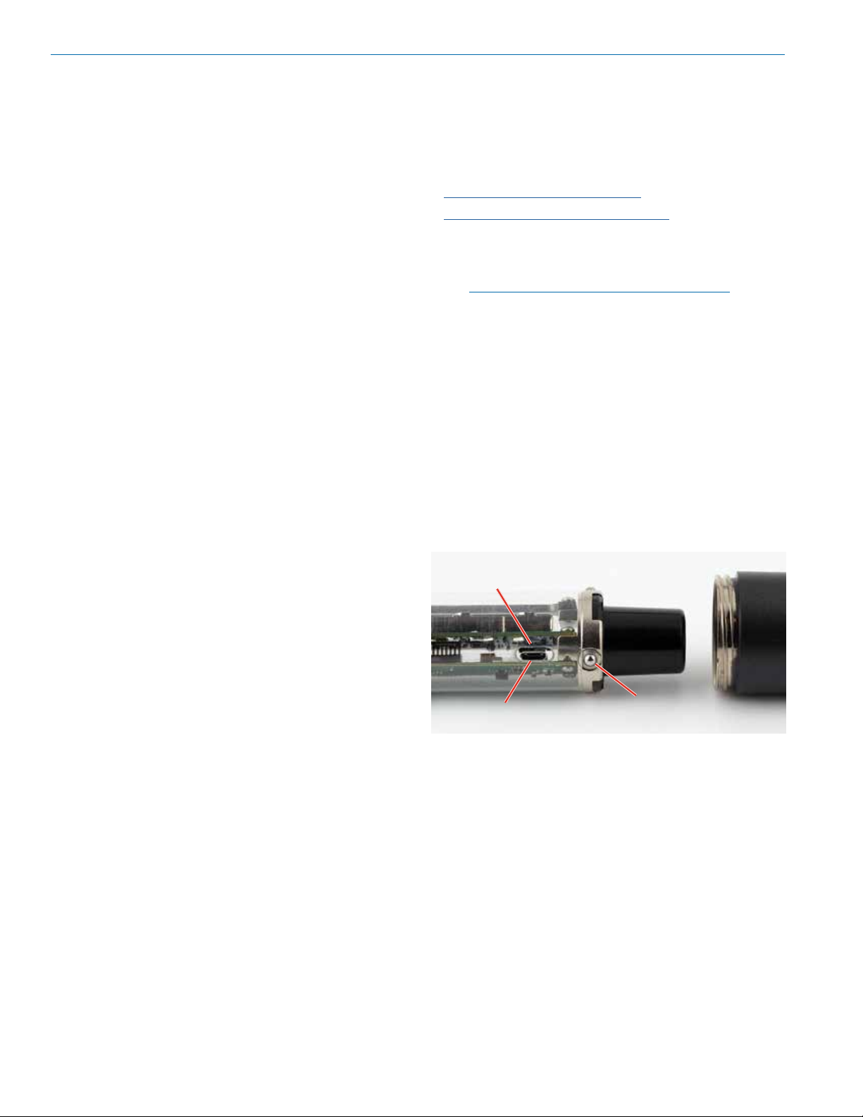
Firmware Update
Instructions
Firmware updates are made with a file downloaded
from the web site and the DBu connected via USB.
The USB port on the transmitter requires a micro-B
male plug on the connecting cable. The other end of
the cable would normally be a USB A-Type male connector to fit the most common type of USB jack used
on computers.
Opening in clear
plastic sleeve
USB Port
Spring-loaded balls
engage detents in housing
Refer to Help in Wireless Designer software for the
procedure.
14
LECTROSONICS, INC.
Page 15

Digital Hand Held Transmitter
Troubleshooting
SYMPTOM POSSIBLE CAUSE
TRANSMITTER WILL NOT POWER ON 1) Batteries are inserted backwards.
2) Batteries are dead, or too low to be used.
MODULATION LEDs DO NOT LIGHT 1) Audio Gain set too low.
2) Mic capsule is damaged or malfunctioning. Try a different capsule
or contact the factory for repair.
MODULATION LEDs INDICATE BUT NO SOUND
1) Talkback function is engaged (release the button on the housing).
See p. 10.
2) Check receiver display for audio level indication
3) Receiver on wrong frequency or wrong band.
4) Receiver connected incorrectly to sound system.
5) Transmitter in standby mode.
RECEIVER RF INDICATOR OFF 1) Transmitter not turned on.
2) Transmitter is in “standby” (non-transmitting) mode. Check the
LCD for the antenna/transmission icon status.
3) Batteries are dead or installed backwards.
4) Receiver antenna missing, defective or improperly positioned.
5) Transmitter and receiver not on the same frequency.
6) Operating range is too great.
7) Receiver antenna missing, incorrect frequency or disconnected.
NO SOUND BUT RECEIVER AUDIO LEVEL METER INDICATES SOUND
1) Receiver audio is muted. (Unmute receiver.)
2) Receiver audio output levels set too low.
3) Receiver audio output is disconnected or cable defective
or mis-wired.
4) Sound system or recorder input level is turned down.
DISTORTED SOUND 1) Transmitter Audio Gain set too high. Speak or sing into the
transmitter and check the Audio Level LEDs and/or Audio Level
bar graph in the transmitter LCD and corresponding indicators on
the receiver.
2) Receiver output level may be too high for the sound system or
recorder input.
3) Excessive wind noise or “breath pops.” Microphone may require
an additional wind screen.
4) Mic capsule damaged or defective
HISS AND NOISE -- AUDIBLE DROPOUTS 1) Transmitter Audio Gain set too low. See page 9 for proper audio
gain setting.
2) Receiver antenna missing, defective or obstructed.
3) Operating range too great.
4) Interference may be present. Turn transmitter off and observe the
RF level indicator on the receiver. Change frequency if necessary.
5) With Lectrosonics HHC or HHVMC: return attenuator control
back to default setting of “F” (see opposite page), then readjust
audio gain per instructions on page 9.
EXCESSIVE FEEDBACK 1) Transmitter Audio Gain set too high. Check level adjustment,
reduce receiver output level, or both.
2) Microphone too close to speaker system.
3) Move microphone closer to the user’s mouth and lower the
sound system volume.
Rio Rancho, NM
15
Page 16

DHu
FCC Compliance:
This device complies with FCC radiation exposure
limits as set forth for an uncontrolled environment. This
device should be installed and operated so that its
antenna(s) are not co-located or operating in conjunction with any other antenna or transmitter.
FCC Notice to the End User:
The normal condition of using this device is to keep
the hand at least 20mm away from the base of the
microphone.
ISEDC Notices:
Per RSS-210
This device operates on a no-protection no-interference basis. Should the user seek to obtain protection from other radio services operating in the same
TV bands, a radio licence is required. Please consult
Industry Canada’s document CPC-2-1-28, Optional
Licensing for Low-Power Radio Apparatus in the TV
Bands, for details.
Ce dispositif fonctionne selon un régime de non-brouillage et de non-protection. Si l’utilisateur devait chercher à obtenir une certaine protection contre d’autres
services radio fonctionnant dans les mêmes bandes
de télévision, une licence radio serait requise. Pour en
savoir plus, veuillez consulter le document CPC-2-1-28
d’Industrie Canada intitulé, Délivrance de licences sur
une base volontaire pour les appareils radio de faible
puissance exempts de licence et exploités dans les
bandes de télévision.
Per RSS-Gen
This device complies with Industry Canada’s licenseexempt RSSs. Operation is subject to the following two
conditions:
1) This device may not cause interference
2) This device must accept any interference,
including interference that may cause undesired
operation of the device.
Le présent appareil est conforme aux CNR d’Industrie
Canada applicables aux appareils radio ex¬empts de
licence. L’exploitation est autorisée aux deux conditions suivantes :
1) l’appareil ne doit pas produire de brouillage;
2) l’appareil doit accepter tout brouillage radioélectrique subi, même si le brouillage est susceptible
d’en compromettre le fonctionnement.
16
ISED Notice to the End User:
The normal condition of using this device is to keep
the hand at least 20mm away from the base of the
microphone.
La condition normale d’utilisation de cet appareil est
de garder la main à au moins 20 mm de la base du
microphone.
LECTROSONICS, INC.
Page 17

Digital Hand Held Transmitter
Service and Repair
If your system malfunctions, you should attempt to correct or isolate the trouble before concluding that the equipment needs repair. Make sure you have followed the setup procedure and operating instructions. Check the interconnecting cables and then go through the Troubleshooting section in this manual.
We strongly recommend that you do not try to repair the equipment yourself and do not have the local repair shop
attempt anything other than the simplest repair. If the repair is more complicated than a broken wire or loose connection, send the unit to the factory for repair and service. Don’t attempt to adjust any controls inside the units.
Once set at the factory, the various controls and trimmers do not drift with age or vibration and never require readjustment. There are no adjustments inside that will make a malfunctioning unit start working.
LECTROSONICS’ Service Department is equipped and staffed to quickly repair your equipment. In-warranty repairs
are made at no charge in accordance with the terms of the warranty. Out-of-warranty repairs are charged at a modest flat rate plus parts and shipping. Since it takes almost as much time and effort to determine what is wrong as it
does to make the repair, there is a charge for an exact quotation. We will be happy to quote approximate charges by
phone for out-of-warranty repairs.
Returning Units for Repair
For timely service, please follow the steps below:
A. DO NOT return equipment to the factory for repair without first contacting us by letter or by phone. We need to
know the nature of the problem, the model number and the serial number of the equipment. We also need a
phone number where you can be reached 8 A.M. to 4 P.M. (U.S. Mountain Standard Time).
B. After receiving your request, we will issue you a return authorization number (R.A.). This number will help
speed your repair through our receiving and repair departments. The return authorization number must be
clearly shown on the outside of the shipping container.
C. Pack the equipment carefully and ship to us, shipping costs prepaid. If necessary, we can provide you with the
proper packing materials. UPS is usually the best way to ship the units. Heavy units should be “double-boxed”
for safe transport.
D. We also strongly recommend that you insure the equipment, since we cannot be responsible for loss of or
damage to equipment that you ship. Of course, we insure the equipment when we ship it back to you.
Mailing address: Shipping address: Telephone:
Lectrosonics, Inc. Lectrosonics, Inc. (505) 892-4501
PO Box 15900 581 Laser Rd. (800) 821-1121 Toll-free
Rio Rancho, NM 87174 Rio Rancho, NM 87124 (505) 892-6243 Fax
USA USA
Web: E-mail:
www.lectrosonics.com sales@lectrosonics.com
Lectrosonics Canada:
Mailing Address: Telephone: E-mail:
720 Spadina Avenue, (416) 596-2202 Sales: colinb@lectrosonics.com
Suite 600 (877) 753-2876 Toll-free Service: joeb@lectrosonics.com
Toronto, Ontario M5S 2T9 (877-7LECTRO)
(416) 596-6648 Fax
Rio Rancho, NM
17
Page 18

DHu
18
LECTROSONICS, INC.
Page 19

Digital Hand Held Transmitter
Rio Rancho, NM
19
Page 20

LIMITED ONE YEAR WARRANTY
The equipment is warranted for one year from date of purchase against defects in
materials or workmanship provided it was purchased from an authorized dealer. This
warranty does not cover equipment which has been abused or damaged by careless
handling or shipping. This warranty does not apply to used or demonstrator equipment.
Should any defect develop, Lectrosonics, Inc. will, at our option, repair or replace any
defective parts without charge for either parts or labor. If Lectrosonics, Inc. cannot
correct the defect in your equipment, it will be replaced at no charge with a similar new
item. Lectrosonics, Inc. will pay for the cost of returning your equipment to you.
This warranty applies only to items returned to Lectrosonics, Inc. or an authorized
dealer, shipping costs prepaid, within one year from the date of purchase.
This Limited Warranty is governed by the laws of the State of New Mexico. It states the
entire liablility of Lectrosonics Inc. and the entire remedy of the purchaser for any
breach of warranty as outlined above. NEITHER LECTROSONICS, INC. NOR
ANYONE INVOLVED IN THE PRODUCTION OR DELIVERY OF THE EQUIPMENT
SHALL BE LIABLE FOR ANY INDIRECT, SPECIAL, PUNITIVE, CONSEQUENTIAL,
OR INCIDENTAL DAMAGES ARISING OUT OF THE USE OR INABILITY TO USE
THIS EQUIPMENT EVEN IF LECTROSONICS, INC. HAS BEEN ADVISED OF THE
POSSIBILITY OF SUCH DAMAGES. IN NO EVENT SHALL THE LIABILITY OF
LECTROSONICS, INC. EXCEED THE PURCHASE PRICE OF ANY DEFECTIVE
EQUIPMENT.
This warranty gives you specific legal rights. You may have additional legal rights which
vary from state to state.
20
581 Laser Road NE • Rio Rancho, NM 87124 USA • www.lectrosonics.com
+1(505) 892-4501 • fax +1(505) 892-6243 • (800) 821-1121 US and Canada • sales@lectrosonics.com
30 May 2019
 Loading...