

Page 1
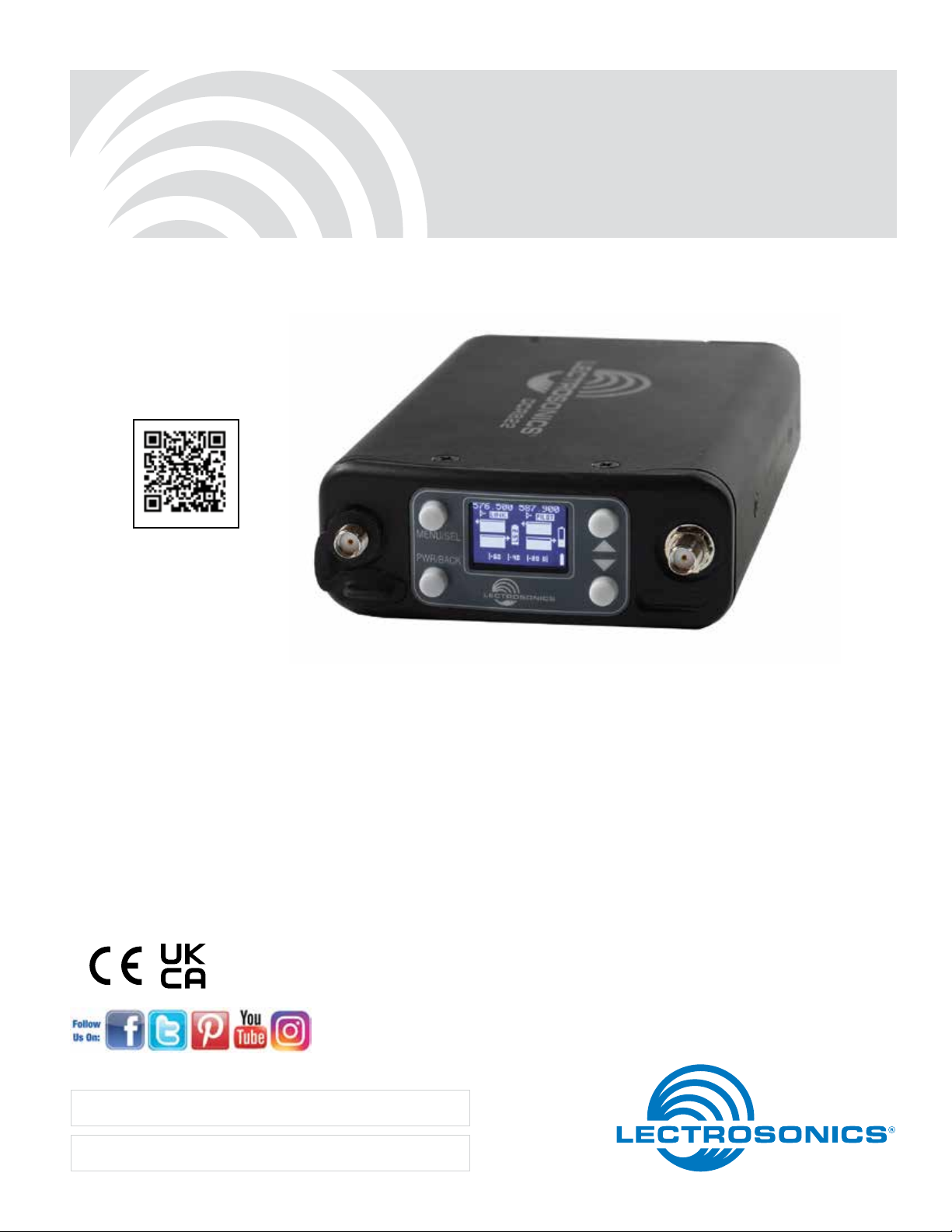
DCR822
Compact Dual Channel Digital Receiver
DCR822-A1B1, DCR822-B1C1, DCR822-941
scan for informational
product video
INSTRUCTION MANUAL
Quick Start Summary
The following checklist includes the minimum required
settings to start using the receiver.
• Connect power to the receiver or install batteries.
• Set the COMPAT (compatibility) mode for the transmitters to be used.
• Choose clean frequencies for your receiver channels using SmartTune or RF scan.
• Set transmitters on the matching frequencies (see
your transmitter manual) or use IR sync.
Fill in for your records:
Serial Number:
• Verify transmitters are set to the same compatibility
mode as the receiver (see your transmitter manual).
• Adjust transmitter input gain to match voice level
and mic position (see your transmitter manual).
• Select audio output type to match camera or mixer
input (analog or AES3 digital).
• Adjust receiver output level as needed for the
camera or mixer input level desired.
• Turn on transmitter RF signals (see your transmitter
manual).
Purchase Date:
Rio Rancho, NM, USA
www.lectrosonics.com
Page 2

DCR822
2
LECTROSONICS, INC.
Page 3

Table of Contents
General Technical Description ....................................4
Compatibility with microSDHC memory cards ..........6
Front Panel Controls and Functions ...........................7
MENU/SELECT Button ...............................................7
PWR/BACK Button ......................................................7
Up/Down Arrow Buttons ..............................................7
IR (infared) Port ........................................................... 7
microSDHC Memory Card Port ................................... 7
Antenna Port (2) .......................................................... 7
Rear Panel Features .....................................................7
TA3 Audio Output Jacks ..............................................7
Power Input Jack .........................................................7
USB Port .....................................................................7
Battery Compartment ..................................................7
LCD Main Window.........................................................8
Navigating the Menus ..................................................8
Main Window Screens ................................................. 8
Replacing the Batteries ................................................9
DCR822 LCD Menu Map ............................................. 10
Menu Item Descriptions ............................................. 13
RF Setup ...................................................................13
Using Diversity Modes ............................................14
Audio Setup ...............................................................15
Compat Mode ............................................................ 15
SD Card Settings.......................................................16
IR & Keys Menu .........................................................17
Encryption Key Management ....................................18
Settings Menu ...........................................................18
Antenna Mounting and Orientation ..........................19
Antenna/Block Reference Table ................................21
Installation and Operating Instructions ....................22
Scan Function/Finding Clear Frequencies ................22
Locking and Unlocking the Front Panel Controls .......22
Firmware Update ........................................................23
Diagnostics .................................................................24
Pilot Tone Bypass ......................................................24
Supplied Parts and Accessories ............................... 25
Optional Parts and Accessories ...............................25
Troubleshooting ..........................................................27
Specifications and Features ...................................... 28
Service and Repair .....................................................29
Returning Units for Repair ......................................... 29
Dual Channel Digital Receiver
Rio Rancho, NM
3
Page 4
DCR822
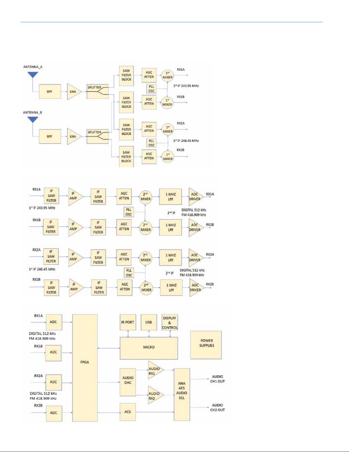
General Technical Description
DCR822 Block Diagram
4
LECTROSONICS, INC.
Page 5

Dual Channel Digital Receiver
The DCR822 digital 2-channel receiver is the true
successor to the venerable UCR411a - a dual-channel
package in the same size - and represents state-of-theart RF performance with Vector Diversity (an advanced
type of true diversity) and extremely robust front-end
architecture, bringing the highest level of RF and audio
performance to field and location production.
Extremely high Third Order Intercept (IP3) performance
of +15 dBm, 24-bit/48 kHz audio performance, and
AES-256 CTR mode encryption ensure that professionals in all audio disciplines have the tools needed to get
the job done, even in extremely tough environments.
On-board recording in .WAV (BWF) format via microSDHC card give this receiver unique possibilities for
different workflows.
Compatibility Modes
The DCR822 receiver was designed to operate with
Lectrosonics digital transmitters from the D2, DCH and
M2 series. The receiver is also backward compatible
with Digital Hybrid Wireless® transmitters including
those with NA Hybrid, NU Hybrid, JA HYBRID and EU
Hybrid modes.
Encryption
The DCR822 receiver features AES 256-bit, CTR mode
encryption, with 4 different key policies available.
Vector Diversity Reception
The DCR822 technology with Lectrosonics Vector Diversity (an advanced version of true diversity) minimizes
dropouts in situations where multi-path reflections can
cause serious problems. Traditional true diversity or
ratio diversity methods work well for FM and Hybrid systems but fall short of the ideal for today’s digital receivers. The DCR822’s Vector Diversity subsystem delivers
clean, artifact-free performance by combining the two
receiver signals via a unique phase-matching system
for maximum RF signal to noise.
RF Frequency Tracking Front-End and Mixer
In addition to the extremely high IP3 capability of the
receiver, to significantly reduce unwanted interference and intermodulation problems, the DCR822 has
a frequency selective front-end section that tracks and
tunes to the desired signal frequency and rejects unwanted interfering signals. The low noise, high current
RF amplifier was designed with feedback regulation for
stability and precise gain in order to handle stronger RF
signals without output overload. This produces a robust
front-end that is as selective as fixed single frequency
designs and is suitable for use in close proximity to
other receivers and transmitters commonly used in field
production bag systems.
Smart Noise Reduction (SmartNR™)
The DCR822 has been meticulously designed using
the best available low noise components and techniques. Nonetheless, the wide dynamic range of digital
and Hybrid transmission technology, combined with
flat response to 20 kHz, makes it possible to hear the
Rio Rancho, NM
-120 dBV noise floor in the transmitter’s mic preamp,
or the (usually) greater noise from the lav microphone
itself. (To put this in perspective, the noise generated
by the recommended 4k bias resistor of many electret
lavaliere mics is –119 dBV and the noise level of the
microphone’s electronics is much higher.) In order to reduce this noise and thus increase the effective dynamic
range of the system, the DCR822 is equipped with a
selectable Smart Noise Reduction algorithm, which removes hiss without sacrificing high frequency response.
The Smart Noise Reduction algorithm works by attenuating only those portions of the audio signal that fit
a statistical profile for randomness or “electronic hiss.”
Desired high frequency signals having some coherence
such as speech sibilance and tones are not affected.
The Smart Noise Reduction algorithm has three modes
- OFF/NORMAL/FULL - selectable from a user setup
screen. When switched OFF (the default setting for
digital compat modes) no noise reduction is performed
and complete transparency is preserved. All signals
presented to the transmitter’s front end, including any
faint microphone hiss, will be faithfully reproduced at the
receiver. When switched to NORMAL, (the factory default setting for Hybrid modes) enough noise reduction
is applied to remove most of the hiss from the mic preamp and some of the hiss from lavaliere microphones.
The noise reduction benefit is dramatic in this position,
yet the degree of transparency maintained is exceptional. When switched to FULL, enough noise reduction
is applied to remove most of the hiss from nearly any
signal source of reasonable quality, assuming levels
are set properly at the transmitter. This additional noise
reduction comes at the cost of some transparency for
low-level room noise, yet the algorithm remains undetectable under most circumstances.
Audio Output Level
A setup screen is provided for adjusting the audio output level in 1 dB increments from -50 to +7 dBu using
the front panel MENU/SEL, UP, and DOWN buttons.
Test Tone
To assist in matching the audio levels of equipment connected to the DCR822, a 1 kHz audio test tone, adjustable from -50 to +7 dBu in 1 dB increments, is available
at the outputs. If using AES3 outputs, the level is fixed
and cannot be adjusted.
Batteries
The DCR822 can operate on four disposable, 1.5VDC
AA Lithium batteries (recommended). Alkaline is not
advised.
Power Supply
The DCR822 may also be operated from an external DC
power source (see Specifications & Features section for
allowed voltages.) The receiver has a built-in Poly-Fuse
for protection. This fuse automatically resets if the power
supply is disconnected for about 15 sec. The power section also has protection circuits that prevent damage to
the receiver if a positive ground power source is applied.
5
Page 6
DCR822
OLED Display
The display has four primary “home” windows. Pressing
the Front Panel PWR/BACK button steps through each
of these windows. Pages 8 and 9 show illustrations and
features of each.
After power is turned off and back on again, the unit
defaults to the Main window and to the most recent
frequencies, audio levels, transmitter battery conditions,
and other user settings. These settings are retained
even if the batteries are removed. The display illumination can be set to time out in 5 seconds, 30 seconds, or
never.
Recorder Function
The DCR822 has a built in recording function for use
in situations where the absolute minimum equipment is
necessary, or as a backup to the main recorder system.
The recorder samples at 48kHz rate with a 24 bit
sample depth. The micro SDHC card also offers easy
firmware update capabilities without the need for a USB
cable or driver issues.
Clock Function
The DCR822 has a built-in calendar and clock that are
saved with power down. If the batteries are removed
from the unit, the DCR822 “remembers” where it left off
and resumes time and date counts from that point.
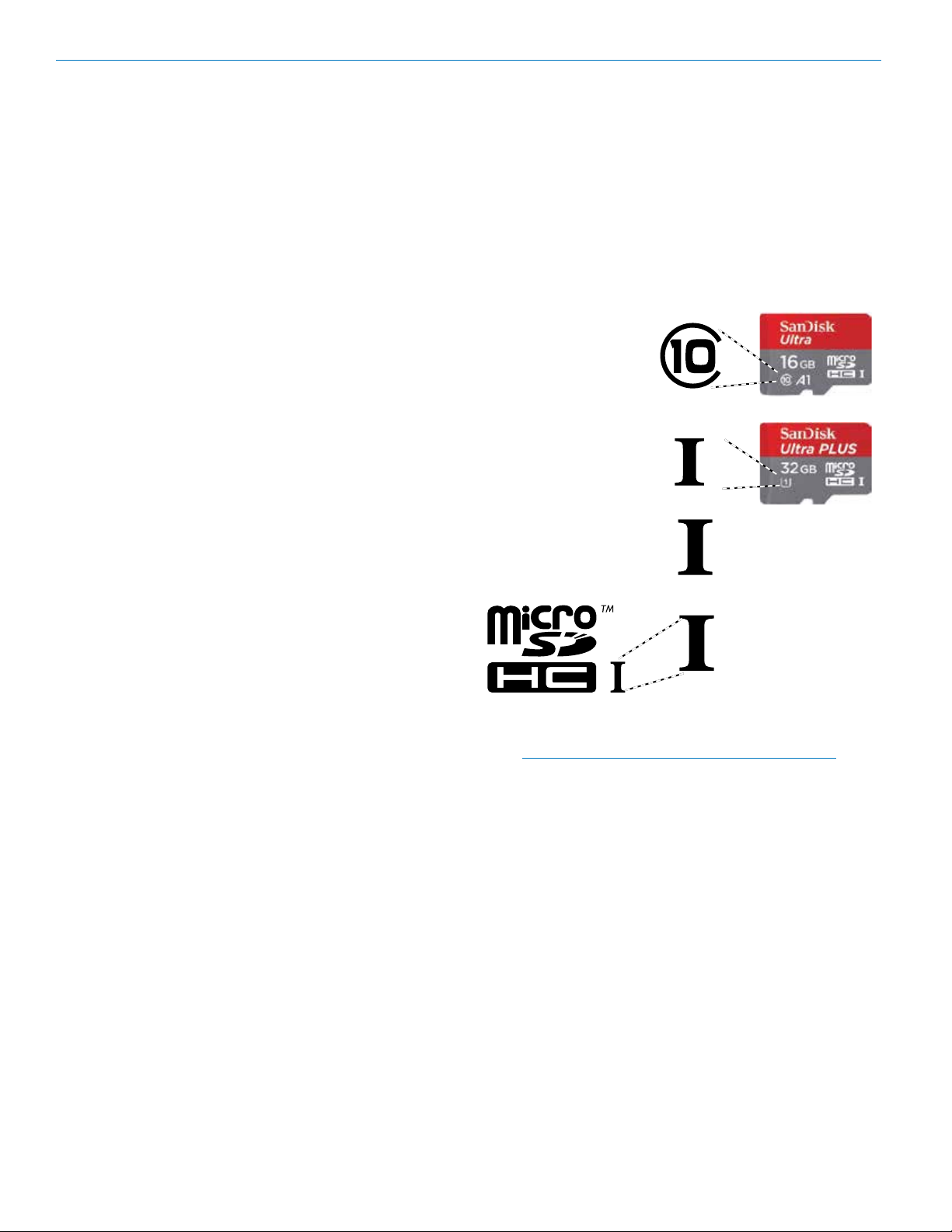
ONLY microSDHC memory cards should be used. They
are available in capacities from 4GB to 32GB. Look for
the Speed Class 10 cards (as indicated by a C wrapped
around the number 10), or the UHS Speed Class I cards
(as indicated by the numeral 1 inside a U symbol). Also
note the microSDHC Logo.
If you are switching to a new brand or source of card,
we always suggest testing first before using the card on
a critical application.
The following markings will appear on compatible
memory cards. One or all of the markings will appear on
the card housing and the packaging.
Speed Class 10
UHS Speed Class 1
UHS Speed Class I
Stand-alone
Power Off
When the Front Panel Power/Back button is pressed
for several seconds, the audio output is instantly muted
(squelched) and the message “POWERING OFF...” is
displayed briefly before the receiver switches off.
Compatibility with
microSDHC memory cards
Please note that the DCR822 is designed for use with
microSDHC memory cards. There are several types of
SD card standards (as of this writing) based on capacity
(storage in GB).
SDSC: standard capacity, up to and including 2 GB –
DO NOT USE!
SDHC: high capacity, more than 2 GB and up to and
including 32 GB – USE THIS TYPE.
SDXC: extended capacity, more than 32 GB and up to
and including 2 TB – DO NOT USE!
SDUC: extended capacity, more than 2TB and up to
and including 128 TB – DO NOT USE!
The larger XC and UC cards use a different formatting
method and bus structure and are NOT compatible with
the recorder. These are typically used with later generation video systems and cameras for image applications
(video and high resolution, high speed photography).
UHS Speed Class I
Accompanying
microSDHC logo
microSDHC Logo is a trademark of SD-3C, LLC
NOTE: The default format for a card formatted on a
computer is always DATA. DATA format is needed
when downloading files for Firmware updates or
for saving frequency groups. When formatting a
card in the DCR822 for audio applications, the
DCR822 will ask if you are formatting for audio, in
which case, any files on the card will be lost.
6
LECTROSONICS, INC.
Page 7
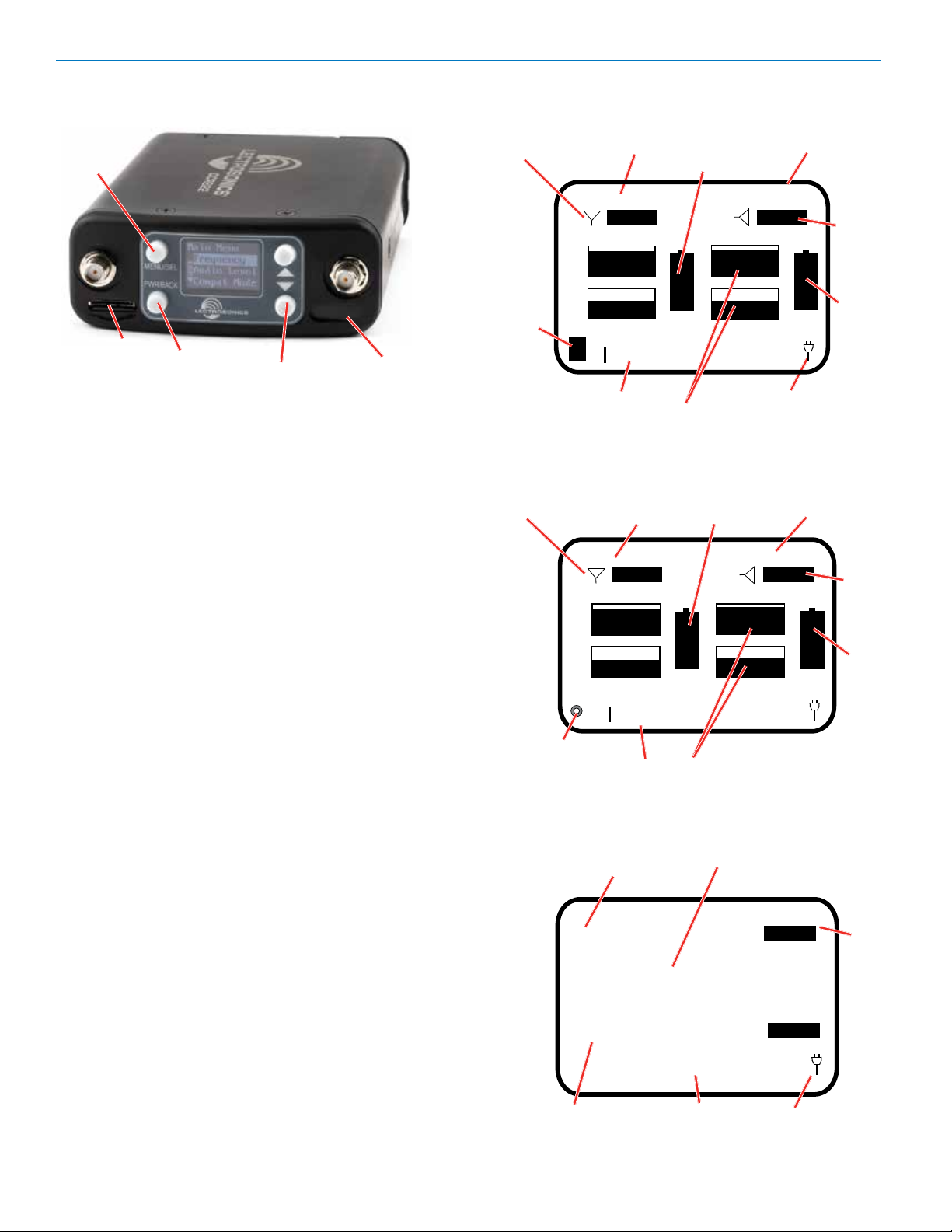
Front Panel Controls and Functions
Audio
+
Audio
-
MENU/SEL Button
The MENU button accesses the available menus and
selects the desired setting.
PWR/BACK Button
The PWR/BACK button is used to turn the receiver on
and off. When browsing menus and making changes to
settings, press PWR/BACK to return to previous menu.
Up/Down Arrow Buttons
The UP/DOWN buttons are used to scroll or input the
various options within each menu selection.
IR (infrared) Port
Settings can be transferred between transmitter and
receiver or receiver and receiver.
microSDHC Memory Card Port
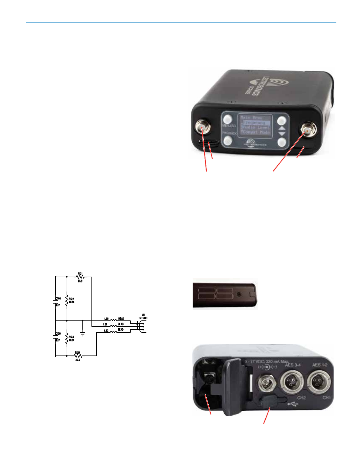
microSDHC memory
Antenna port
Dual Channel Digital Receiver
IR (infrared) port
card port
Antenna port
Antenna Port (2)
Rear Panel Features
TA3 Audio Output Jacks
The DCR822 uses a standard TA3 configuration with
pin 2 “positive.” The audio output is balanced but not
floating, so an unbalanced signal is available using pin
1 as ground and pin 2 as signal, leaving pin 3 open
(audio level will be 6 dB lower than balanced).
USB Port
The microB USB port can be used to connect the
DCR822 to the Lectrosonics Wireless Designer software (pending; capability will be built into a future
firmware update).
Battery Compartment
installed as marked on
the side panel of the
receiver.
The battery door is hinged and remains attached to the
housing when open. The specially-designed latch snaps
and locks into place for security when closed.
Four AA batteries are
Power Input Jack
The power input jack can accept 9-17 VDC - the center
pin is positive and sleeve is ground. The input is diode
protected to prevent damage if the power is applied
with reversed polarity, and the unit will not work until the
reversed polarity condition is corrected.
Rio Rancho, NM
Battery
Compartment
USB Port
7
Page 8
DCR822
LCD Main Window
MENU/SEL
button
Antenna
Status
CH1
Frequency
Transmitter 1
Battery Status
CH2
Frequency
SD Card Slot
PWR/BACK
button
UP/DOWN
buttons
IR Port
Navigating the Menus
From the Main Window, press MENU/SEL to enter the
menu, then navigate with the UP and DOWN arrows to
highlight the desired setup item. Press MENU/SEL to
enter the setup screen for that item. Refer to the menu
map on pages 10-12.
Main Window Screens
The Main Window displays information concerning the
RF levels at each antenna per channel, audio modulation levels, the condition of the Pilot Tone (Hybrid) or
Link (digital), and battery conditions for both the receiver and the associated transmitters. It is also the access
portal to menu selections for setting up the receiver
and searching for clear frequency channels.(See Menu
Selections from Main window and Frequency Scan
Mode). The PWR/BACK button will cycle the display
through four different, additional screen configurations,
containing various combinations of transmitter names,
RF signal strength meters and audio meters, depending
on user preference.
• Receiver Battery icon changes to a plug icon
when external power is supplied.
• SD Card Status: No card, card error, data card,
stopped (ready to record), recording.
• Antenna Icons: Status of the vector diversity system.
• Transmiter Battery Status Icons: Appear when
the receiver’s battery status is known and can take
on different appearances, depending on user settings.
• RF Signal Strength Strip Charts: RF signal
strength indicators.
• Channel Status Indicator: Pilot tone, link and
encryption system status.
• Keypad Shortcut: Can start or stop recording from
the Main Window: MENU+UP to begin recording
and MENU+DOWN to stop recording.
SD Card
Status
(recording
stopped)
Antenna
Status
SD Card
Status
(recording)
Frequency
LINK
|-60 |-40 |-20 0|
Audio Level
Strip Charts
CH1
Name
LINK
|-60 |-40 |-20 0|
Audio Level
CH1
Frequency
537.600
|-60 |-40 |-20 0|
537.600
|-60 |-40 |-20 0|
CH2
Audio Level
RF Signal
Transmitter 1
Battery Status
RF Signal
Strip Charts
CH1
Audio Level
CH2
LINK
Plug (or battery)
Icon
CH2
Name
LINK
LINK
LINK
Plug (or battery)
Icon
Channel
Status
Indicator
Transmitter 2
Battery Status
Channel
Status
indicator
Transmitter 2
Battery Status
Channel
Status
indicator
8
LECTROSONICS, INC.
Page 9
CH2
Name
CH1
Name
Tx1
|-60 |-40 |-20 0|
Tx2
D
|-60 |-40 |-20 0|
CH1
Audio Level
LINK
LINK
Dual Channel Digital Receiver
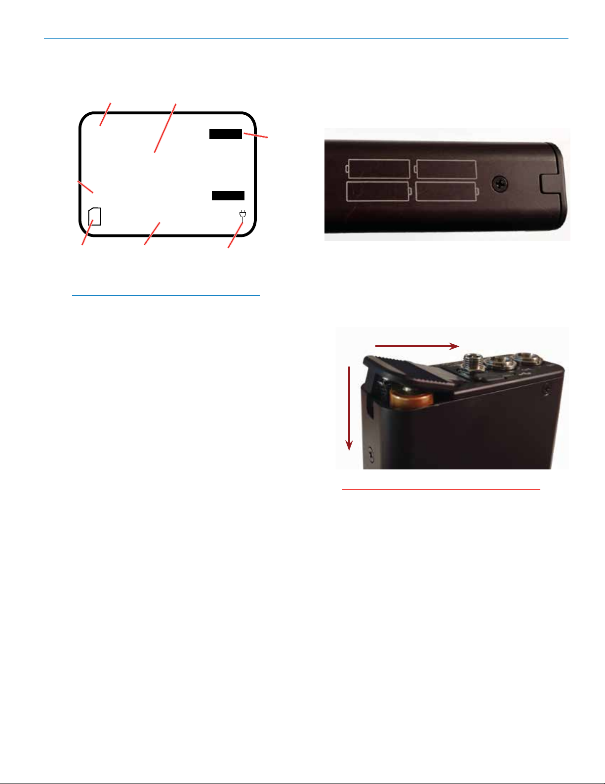
Replacing the Batteries
Lift the battery door to unlatch, push slightly forward
and open it.
Observe the battery orientation markings on the side of
the unit.
Channel
Status
indicator
SD Card
Status
(data
card)
NOTE: If Link Indicator is flashing, this indicates
that the key or compat mode is invalid.
CH2
Audio Level
Plug (or battery)
Icon
Depress the batteries slightly to allow the door to close,
then press with down firmly while pushing back towards
the DC connector to latch the door closed. The battery
contacts are spring loaded to maintain constant pressure. The door will snap into place for security when it is
fully closed.
Slide back to latch
Press
down
CAUTION: Be sure to remove batteries as soon
as possible after they are depleted.
Rio Rancho, NM
9
Page 10
DCR822
DCR822 LCD Menu Map
The menus presented on the LCD are arranged in a straightforward manner, with those that are likely to be used
more often located at the top of the tree.
Main Menu Tree
Scroll options with arrow buttons
RF Setup
Smart Tune
Frequency
Smart Tune
Tune Rx 1
Frequency 1
607.900
Grp u
Use arrow buttons to scroll
Select Freq or Grp with arrow buttons
through range options
to toggle.
Tx1 Range?
A1B1
to
select.
Searching...
470.600
Tuned Rx 1
525.100
Selects an open frequency.
Choose Down Arrow to Sync.
to repeat and tune RX 2
Sync!
* After adding a group,
navigate to SD Card,
then Save Group,
then Save to Card to
share groups with other
units.
* Pilot Tone Bypass
is only available in
Hybrid Compat Modes
Audio Setup
* Option will be fixed
if Frequency Diversity
is chosen.
Scan
Clear Scan
Group Edit
Diversity
PilotBypass
Audio Level
Output Type
Routing
Smart NR
Scanning... 1
607.000
Scan
data
CLEARED
Group Edit u
(empty)
MENU + å to ADD
MENU + ã to DEL
Diversity
Vector
PilotBypass
OFF
ON
Audio Level
[ AES] +1
MENU+å 1ktone
|-60 |-40 |-20 0|
Output Type
AES3 ANLG
Routing
RX1: ANLG1
RX2: ANLG2
Smart NR
NORM
to pause scan
to select
channel.
After scan clears it automatically
reverts to back the main menu tree.
Use arrows to scroll and add
freq range and groups. Use
MENU+UP to
save; MENU+
DOWN to
delete.
Scroll options with arrow buttons. If you choose Frequency,
the system will ask you to Calibrate first.
PWR
BACK
to select.
Select option with arrow buttons
PWR
to select.
BACK
Select values with arrow buttons
to toggle.
Select option with arrow buttons
PWR
to toggle.
BACK
Select option with arrow buttons
PWR
to toggle.
BACK
Select option with arrow buttons
PWR
to toggle.
BACK
Press both together
to zoom view
MENU+UP to output audio tone
for calibration.
While paused, use UP or Down arrows
to tune selected receiver
* Option not available
if Frequency Diversity
is chosen.
CompatMode
SD Card
10
Talkback
Polarity
CompatMode 1
D2
Files
Takes
Record
Talkback 1
ON
Polarity
Pos. Neg.
Select option with arrow buttons
PWR
to toggle.
BACK
Select option with arrow buttons
to toggle.
Select option with arrow buttons
to toggle.
Files
0002.WAV
0003.WAV
Takes
S01 T002
S02 T003
Scroll with arrow buttons
to select.
Scroll with arrow buttons
to select.
Recording
to stop/save.
0003 .WAV
Date 6/15
LTime 09:53
Len 00:10:25
S02 T003
Date 6/15
LTime 09:53
Len 00:10:25
LECTROSONICS, INC.
Page 11

Select option with arrow buttons
to toggle.
CompatMode
CompatMode 1
D2
Takes
Scroll with arrow buttons
to select.
Files
to stop/save.
SD Card
Files
0002.WAV
0003.WAV
0003 .WAV
Date 6/15
LTime 09:53
Len 00:10:25
Takes
S01 T002
S02 T003
S02 T003
Date 6/15
LTime 09:53
Len 00:10:25
Record
Recording
Change values with arrow buttons
Polarity
Pos. Neg.
Select option with arrow buttons
to toggle.
Polarity
Scroll with arrow buttons
to select.
DCR822 LCD Menu Map
* “No” leaves the card
formatted for Data.
Data format is needed
for firmware updates or
saving frequency groups.
Scene&Take
Format Card
File Naming
Load Group
Scene&Take
Scene 1
S0Scene 2
Format Card
for audio?
(files lost)
File Naming
Sequence
Clock Time
Scene&Take
Files
Group9 .GRP
Group8 .GRP
Group7 .GRP
Save Group
E...............F
0/14G
About Card
Max. Rec. Time
15:05:52
Next File
S01T004
No
Yes
GROUPS
SAVED
TO
CARD
to select.
Select option with arrow buttons
to select.
Select option with arrow buttons
PWR
to select.
BACK
Scroll with arrow buttons
to select.
PWR
BACK
Dual Channel Digital Receiver
IR & Keys
* If an Encryption Key
exists, this option
will be Wipe Key,
providing the option to
delete and start over.
Settings
Send Freq
Send All
Get Freq
Get All
Group Sync
Key Type
Make Key
Send Key
Lock/Unlock
Send Freq
Sync 1 --->
Sync 2 --->
Send All
Sync 1 --->
Sync 2 --->
Get Freq
Sync 1 --->
Sync 2 --->
Get All
Sync 1 --->
Sync 2 --->
Group Sync
Group x
Send
Key Type
Standard
Make Key?
No
Yes
Send Key
Send --->
Lock/Unlock
Locked
Unlocked
Use UP/DOWN
buttons to sync
Select option with arrow buttons
to select.
Sync!
DOWN ARROW initiates sync.
Select option with arrow buttons
PWR
to select.
BACK
Select option with arrow buttons
to select.
DOWN arrow initiates
sync.
Select option with arrow buttons
to select.
IR
SYNC
OK
IR
SYNC
OK
IR
SYNC
OK
IR
SYNC
OK
IR
SYNC
OK
Encrytion
key
CREATED
IR
SYNC
OK
Rio Rancho, NM
Backlight
RX Power
Backlight
Always on
30 Seconds
5 Seconds
RX Power
On On
Select option with arrow buttons
PWR
to select.
BACK
Select option with arrow buttons
PWR
to toggle
BACK
11
Page 12

Lock/Unlock
RX Power
RX Power
Backlight
Backlight
Always on
30 Seconds
5 Seconds
Select option with arrow buttons
to select.
On On
Select option with arrow buttons
to toggle
Settings
Locked
Unlocked
Select option with arrow buttons
to select.
Lock/Unlock
Select option with arrow buttons
to select.
Select option with arrow buttons
to select.
Get All
Sync 1 --->
Sync 2 --->
Get All
Group Sync
Group Sync
Group x
Send
Sync!
Key Type
Key Type
Standard
Make Key
Make Key?
No
Yes
Select option with arrow buttons
to select.
Encrytion
key
CREATED
* If an Encryption Key
exists, this option
will be Wipe Key,
providing the option to
delete and start over.
Send Key
Send Key
Send --->
DOWN arrow initiates
sync.
IR
SYNC
OK
PWR
BACK
PWR
BACK
PWR
BACK
IR
SYNC
OK
IR
SYNC
OK
DOWN ARROW initiates sync.
DCR822
DCR822 LCD Menu Map
* For Digital transmitters,
select Batt Type in the
transmitter.
RXBat Type
TXBat Type
TXBat Timer
TXBat Icon
Auto On
Edit Names
Date & Time
Locale
Default
TX Bat Type
RX Bat Type
Alk.
Lith.
Alk.
Lith.
TX Bat Timer 1
Time: 1:33
No Alert
MENU+å to reset
TxBat Icon
Bar Bar
Auto On?
Enabled
Disabled
Edit Names
1: TX1
2: TX2
Date & Time
2000/01/28
00:32:16
Locale
NA
EU
Restore
defaults?
No
Yes
Select option with arrow buttons
PWR
to select.
BACK
Select option with arrow buttons
PWR
to select.
BACK
Select option with arrow buttons
to toggle.
Select option with arrow buttons
PWR
to toggle.
BACK
Select option with arrow buttons
to select.
PWR
BACK
Select values with arrow buttons
to move
cursor.
Select values with arrow buttons
to move
cursor.
Select option with arrow buttons
PWR
to select.
BACK
Select option with arrow buttons
to confirm.
About
About
Band B1C1
V1.12
/1.09
to go back.
12
LECTROSONICS, INC.
Page 13

Dual Channel Digital Receiver
Menu Item Descriptions
RF Setup
Finding Clear Frequencies with SmartTune:
SmartTune is the easiest and fastest way to scan the
local RF spectrum and find clear operating frequencies. The receiver will scan through the selected tuning
bandwidth and automatically find “empty” areas within
the tuning range that have little or no RF energy. The
receiver will then be set to a frequency within an empty
area and prompt you to continue or use the IR function
to sync to a transmitter.
Note: Pressing BACK during an active scan will
restore the operating frequency to what it was set
at pre-scan.
Transmit frequency range is compatibility mode dependent (see Compat Mode for further details). Tune
Receiver 1 is the first screen you will see when you
enter SmartTune. After selecting either Tune Rx1 or 2,
using the UP/DOWN buttons, press MENU/SEL to open
the TX Range? page, then use the UP/DOWN buttons
to select the frequency range of the transmitter.
After choosing the band, the unit will scan the available
frequency and choose the frequency with the lowest
interference and will display it as shown, with a “Sync!”
icon in the lower right corner of the screen.
Tuned Rx 1
525.100
Sync!
Face the transmitter’s IR port within a foot of the receiver’s IR port and press the DOWN button to begin the
sync. In digital compat modes, if the sync is successful, the message “IR Sync OK” will appear on screen. If
unsuccessful, the message will show “IR Sync Failed”.
For Hybrid compat modes, “Sync!” at the lower right will
blink, but the sync status will only show on the transmitter’s display. the transmitter’s IR port within a foot of the
receiver’s IR port and press the DOWN button to begin
the sync. If sync is successful, the screen will display
“IR Sync OK.” If unsuccessful, the screen will display “IR
Sync Failed.”
After the sync of Channel 1, choose MENU/SEL and
the screen will ask Do RX 2 Next? Use the UP/DOWN
buttons to toggle between Yes and No; use MENU/SEL
to confirm. The screen will ask if you have Transmitter
1 on. This ensures that the transmitters are tuned in a
way that they don’t interfere with each other.
It will then ask for TX2 Range? After you choose your
range, choose MENU/SEL and the DCR822 will search
for a clear frequency. It will ask to sync. Press the
DOWN button to sync the transmitter to the receiver.
When complete, press PWR/BACK to return to the
MAIN SCREEN.
Frequency:
Allows manual selection or group tuning of the operating frequency for each channel. The frequency setup
screen has different fields depending on mode selected.
In digital modes, with no tuning group selected, the
frequency setup page has four fields: receiver name,
MHz, kHz, and group selector. In Hybrid modes, with no
tuning group selected, the page has six fields: receiver
name, block selector, legacy hex code, MHz, kHz, and
group selector. The block selector can be used for block
disambiguation for any frequencies that overlap between blocks 470 and 19, or between blocks 23-24 and
606.
Frequency
602.050
Grp u
Digital Mode Hybrid Mode
1
Frequency
b 24:1E
602.050
No Grp
1
To manually tune: start by selecting either Channel 1 or
2 in the upper right corner. Then, press MENU/SEL to
select the desired field to edit, using the UP or DOWN
buttons. MHz value can be changed in increments of
1 MHz by pressing the UP or DOWN buttons. To keep
the selected value, press the MENU/SEL button. The
kHz value can be changed in increments of 25 kHz by
pressing the UP or DOWN buttons. Pressing MENU/
SEL and UP or DOWN at the same time tunes in larger
steps. In the MHZ field, in 10 MHz steps; in the kHz
field, in 100 kHz steps.
Tuning groups: Tuning groups are an important feature
within the RF Setup menu that allow the user to create,
store, share, recall, and use lists of frequencies. See
Group Edit below (after Scan, Scan Zoom and Clear
Scan) for how to set up and edit tuning groups. When
a tuning group is assigned on the Frequency page, the
tunable frequencies are limited to those contained in the
group. Press MENU/SEL to move the cursor among the
available options, and the UP and DOWN arrow buttons
to change values.
First, select receiver 1 or 2. Move the cursor again to
the group setting. Use the UP or DOWN arrow select
among groups. Use MENU/SEL again to move the cursor to the frequency selection. Use the UP or DOWN
arrows to scroll among the available frequencies in
that group. UP from the highest frequency in the group
moves to the lowest frequency in the group; DOWN
from the lowest frequency moves to the highest frequency in the group.
Rio Rancho, NM
13
Page 14

DCR822
NOTE: If the frequency is blinking, it means that
the currently tuned frequency is not in the selected
group. If it is steady, it means that the currently
tuned frequency is in the selected group. Choose
No Group to exit the group tuning mode and thus
have access to any frequencies within the tuning
range of the receiver..
• Four tuning groups are available, U, V, W, X, with
each containing up to 32 frequencies.
• Each group has the option to add or delete a frequency from the list on the right. Use the UP and
DOWN arrows to change frequencies, MENU/SEL
to move through the options, and the UP arrow to
select ADD or DELETE. Push the PWR/BACK but-
ton to return to the Frequency Screen.
• Each group can store up to 32 frequencies to the
microSD card.
• The user can also send or get all frequency groups
(through the IR & Sync screen).
To add or remove frequencies from a tuning group, see
Group Edit below.
Scan:
Scans for an open frequency and shows a graphic
representation of RF energy in the area, by frequency.
Press MENU/SEL to begin the scan. You can pause the
scan by pressing MENU/SEL a second time. Pressing
MENU/SEL again changes receiver channels.
Scan Zoom:
To zoom the screen, first pause the screen. Press
the UP+DOWN buttons to see another scan. Pressing MENU/SEL clears changes. To exit the zoomed
view, press UP+DOWN again to return to the previous
screen.
Scan Zoomed
525.100
Clear Scan:
Clears scan results. Highlight CLEAR SCAN in the
menu, then press MENU/SEL. The screen will quickly
show Scan Data Cleared.
Group Edit:
Allows the user to add, and delete frequencies within
the available tuning groups. Use the MENU/SEL button
to move the cursor between the group selector and the
list of frequencies within that group (if any). With the
cursor on the Group selector, use the UP or DOWN ar-
row buttons to select from the four available groups: u,
v, w and x. Once the desired group has been selected,
Press the MENU/SEL button together with the UP but-
ton to add a new frequency to the group. The cursor will
highlight MHz. Use the UP or DOWN buttons to change
the value. Press the MENU/SEL button to move the
cursor to the kHz value. Use the UP or DOWN arrows to
change the value. When finished, press the MENU/SEL
button again, and “Go” will appear at the bottom right.
Press the DOWN button to complete the operation.
To add additional frequencies to the group, follow the
same steps above again. To delete frequencies from the
group, press MENU/SEL to move the cursor to the first
frequency in the list. Then, use the UP or DOWN buttons to select the frequency you wish to remove. Press
the MENU/SEL and DOWN buttons together to delete
that frequency from the list.
To load or save groups to the microSD card, see the
section on SD Card Settings. To share groups via IR
sync, see the section on IR & Keys.
When adding frequencies that may exist in more than
one block (470/19, 23 or 24 and block 606), a prompt
will appea for the applicable block, which then becomes
selectable. The purpose of this is to ensure that the correct pilot tone is used, when in a Digital Hybrid compatibility mode (NA Hyb, EU Hyb, NU Hyb, JA Hyb). The
exact ranges of the overlapping regions are:
· 606.000 to 613.375 MHz: block 23 and block 606
· 614.400 to 631.575 MHz: block 24 and block 606
· 486.400 to 495.675 MHz: block 470 and block 19
Diversity:
Choose between: Vector or Frequency. Diversity
modes safeguard against loss of audio signal caused
by Multipath. If you choose Frequency, the system will
ask you to calibrate. The calibration step is necessary
for matching audio levels between channels for proper
orientation.
Using Diversity Modes
Two diversity reception modes are available:
• Vector Diversity uses one receiver module per
audio channel.
• Frequency Diversity uses two receiver channels
and two transmitters per audio channel. The second receiver will automatically be set to the same
Compat Mode as CH1 when this diversity mode is
selected.
Vector Diversity
Vector Diversity works by expressing the signal from
each antenna in angle and magnitude (vector). This
makes it possible to continuously rotate one of the
vectors mathematically so the angles match and the
signals can be combined constructively. In this way, all
the energy that is available at both antennas is always
fully contributing to the receiver’s performance.
Frequency Diversity
Frequency Diversity differs from vector diversity in that it
uses both receiver channels and two transmitters operating on different frequencies. The purpose of this mode
14
LECTROSONICS, INC.
Page 15

Dual Channel Digital Receiver
is to have redundancy in the system for critical productions, such as live television, to guard against failures
caused by dead batteries and multipath dropouts.
Frequency Diversity requires that the levels of the two
audio channels to be closely matched to avoid audible level changes as the blending action takes place.
In order for this blending to work properly, a special
test mode helps to get the transmitter levels exactly
matched.
Note: In Frequency Diversity mode, both
transmitters must be the same type (usually the
same model). The microphones must also be
placed very close together to minimize comb
filtering.
Diversity
The DCR822 allows null
testing with a special calibration mode as shown on the
display. When the display
shows “calibrate,” it should be
Frequency
Calibrate
possible to achieve a null.
Calibration is automatically
activated on selection of the
Frequency Diversity mode, and automatically cancelled
on exiting the diversity setup page. Calibration can be
toggled on and off for testing but will revert to Operate
mode on exiting the diversity setup page.
both outputs). In the photograph, an MTCR is used.
Plug a set of headphones into the amplifier jack to
monitor the blended output.
3. In the “Calibrate” mode, the two receiver channels
are placed out of polarity from each other. While
listening to the blended output, adjust the gain
control on one of the transmitters so that the audio
level drops significantly (nulls) as the two channels
cancel each other. For the best performance in
Frequency Diversity mode, adjust the mic gain up
and down on one transmitter as described, listening
for the deepest null.
4. Once completed, Press the PWR/BACK button to
exit this screen, which will automatically change
from from “Calibrate” to “Operate”. While still on the
Diversity selection page, you can select “Calibrate”
with the MENU/SEL button, then change to “Operate” by pressing the UP or DOWN buttons.
Pilot Bypass:
Allows the user to bypass the pilot tone on each channel while in a Hybrid compat mode and defeats the pilot
tone squelch when on (no pilot tone is required). “Off”
means that pilot tone must be present to allow audio
output. This setting is compatibility mode dependent. If
this option is not available for the mode you have chosen, the screen will show N/A.
To prepare for operation in the Frequency Diversity
mode, make the following adjustments:
1. Set up the transmitters according to their instructions. Verify that both transmitters are set to the
same audio polarity, and set to the same input gain
level. Turn them on to transmit, and verify that audio
and RF signals are present at the receiver. Place
the two microphone elements as closely together
as possible, and place them where there is a steady
source of sound. Pink noise from a loudspeaker,
headphone, or smartphone is ideal. Make sure it is
loud enough to modulate the receiver audio to the
middle of the range on both channels.
2. Connect a headphone amplifier to one of the audio
outputs on the DCR822 (in Frequency Diversity
mode, the resulting blended audio is mirrored on
WARNING: Without a carrier present (a
transmitter on), the audio will be unsquelched
noise.
Audio Setup
Audio Level:
Allows user to set Audio Output Level per channel and
allows user to enable 1kHz audio tone for level setting.
This setting is Output Type dependent. If AES is chosen, there are no adjustments available.
Output Type:
Allows user to choose output for each channel, analog
or AES3
Routing:
Allows user to choose where to send RX1 and RX2, to
either audio output channel or both.
Smart NR:
Allows user to enable Smart Noise Reduction on either
receiver channel or both. Settings are: Off, Normal and
Full. The default setting for digital compatibility modes is
“Off.” The default setting for hybrid modes is “Normal.”
Talkback:
Allows user to enable the Talkback (TB) function on
either receiver channels or both, to determine where
the TB outputs are routed, and to select how the TB
signals interact with the normal program audio on those
Rio Rancho, NM
15
Page 16

DCR822
outputs. If “Off” is selected for a receiver channel, then
no Talkback function will occur on that channel, even if
the transmitter’s programmable switch is set to “TB” and
activated. “Override” indicates that if a TB command
comes from the transmitter, then the TB audio goes to
the specified receiver output, and the normal audio from
that channel is muted. “Mix” indicates that the TB audio
and the standard audio routed to that receiver output
will be mixed to that output. “TB Only” indicates that the
normal audio routed to that output is muted, and only
the TB audio will be present, and, only when the TB
command is activated on the transmitter.
If AES3 output type is selected on one or both of the
receiver outputs, it is possible to keep the normal audio
on both channels separate from any TB audio. To do
this, have normal audio on receiver channel 1 routed to
AES1L, and the TB audio routed to AES1R. Meanwhile,
receiver channel 2 audio can be routed to AES2L, and
it’s TB audio can be routed to AES2R.
Polarity:
Allows user to set audio polarity of each channel as
either positive or negative.
Compat Modes
Allows user to set compatibility mode per receiver channel. Available modes are: mono digital modes D2 and
HDM (High Density Mode); stereo digital modes Duet
channel 1, 2, or both and DCHX (encrypted) channel
1, 2, or both; and mono Hybrid modes: NA Hybrid, NU
Hybrid, EU Hybrid, and JA Hybrid. EU and JA modes
are not available for Block 941.
Scene & Take:
Allows user to set scene and take file naming starting
point. Subsequent starts and stops of recordings will
increment the take number.
Format Card:
Prompts user for confirmation of erasing files and preparing card for recording of audio files.
File Naming:
Allows users to set the naming format of file between:
- Sequence
- Clock Time
- Scene&Take
Load Group and Save Group:
Tuning groups allows lists of frequencies to be created,
edited, stored and transferred in order to constrain tuning or allow for quick selection of frequencies shared
between devices. Groups are created in the receiver,
then can be shared to other receivers or transmitters
via IR Sync, or by storing the group on a data-formatted
microSDHC card and loading that card onto the target units. To load a pre-existing set of groups from a
data-formatted microSDHC card, choose Load Group,
then select the desired group file by pressing the UP
or DOWN buttons, then press MENU/SEL. To save
frequency groups that have been previously populated,
choose Save Group, then press the MENU/SEL button.
All groups will be saved as .GRP files.
About Card:
Shows the space left on the card, maximum recording
time available on the card and the next file number in
the naming sequence.
SD Card Settings
Files:
Allows user to access list of files saved on the microSD
card in .WAV format. Using the UP/DOWN buttons to
highlight a specific file, the pressing MENU/SEL displays file details including date, time, and length of the
recording.
Takes:
Lists files on the microSDHC card in the Scenes and
Takes format. Files are listed in the form of SXX TXXX.
Selecting a file will display date, time, and length of
recording.
Record:
Starts the DCR822 in recording mode, with files named
and Scenes and Takes sequenced according to the
settings in SD Card>File Naming, and SD Card>Scene
& Take. The number of tracks recorded depends on the
Compat modes chosen on the receiver channels, and
how many channels of audio are present on each. For
instance, if both channels are in Hybrid compat modes
(mono audio on each) then two tracks will be recorded
in the .WAV file. If channel 1 is in D2 mode and channel
2 is in DCHX mode with “Both” selected (2 channels of
audio) then there will be 3 tracks recorded in the .WAV
file.
Recovering an Interrupted Recording
Recordings can be reliably recovered even if the
microSDHC memory card is accidentally removed or
the battery dies while a recording is in progress. If a
recording is interrupted, all of the audio is present on
the card and can be easily recovered by the DCR822.
The DCR822 keeps track of the length of the most
recent recording so it can supply a good suggestion for
the length to recover. If the length is ever unknown or
the DCR822’s suggestion seems incorrect, it is always
possible to override the suggested length. If in doubt,
specify the maximum length possible, in which case
the entire remainder of the card is recovered. All of the
interrupted recording will be present, followed by extra
contents which might be random noise or audio from
previously deleted recordings.
NOTE: Good batteries or an external power supply is
required for the recovery. If recovery is attempted with
weak batteries, a message will appear indicating that
fresh batteries will be required.
Once fresh batteries have been installed, power on the
DCR822 and insert the card with the interrupted recording. The DCR822 will detect the interrupted recording
and display:
16
LECTROSONICS, INC.
Page 17

Dual Channel Digital Receiver
INTERRUPTED
RECORDING
FOUND
And then:
Recover?
for safe use
see manual
No
Yes
If “No” is chosen, nothing is done to the card and the
DCR822 will not use the card. If “Yes” is chosen”, a
prompt appears asking for the length of the recording
to recover, specified as a number of hours and minutes.
The default suggestion will be the approximate length of
the most recent recording. It is always safe to recover a
longer recording than was made. To specify the recovery time, use the MENU/SEL button to navigate and
specify the hours and minutes fields.
Length to
recover?
hh mm
08: 10
Once set as desired, use MENU/SEL to reveal the “GO”
soft button and press the DOWN button button to begin
the recovery process. Recovery is nearly instantaneous.
When completed, the display will show:
RECOVERY
SUCCESSFUL
IR & Keys Menu
The operations below depend on the compatibility mode
selected and the transmitter used. The DCR822 has
two-way IR for use with digital products (DBu, DBSM,
etc.) and one-way IR for use with older IR-capable units
such as LT and HMa. One-way protocol can only “Send
Frequency.”
Send Frequency
Sends operating frequency to the transmitter, each
channel separately. Press the UP button to send the
Channel 1 frequency, and the DOWN button to send the
Channel 2 frequency. Success for digital compat modes
is indicated on the receiver as “IR Sync OK.” For digital
modes, failure will be indicated on the receiver as “IR
SYNC FAILED.” For Hybrid compat modes, success will
be indicated on the transmitter as “IR SYNC.” Failure will
be indicated on the transmitter as “CP Err” or “Block
Mismatch” depending on the transmitter model and the
source of the error.
Send All
(available only for digital compat modes)
Sends frequency, channel name/s, and Talkback state
to the transmitter. Press the UP button to send the
information from Channel 1, and the DOWN button to
send the information from Channel 2. Since two-way IR
Sync is only available for digital transmitters, “N/A” will
be next to any channels that are in a Hybrid compatibility
mode.
Get Frequency
(available only for digital compat modes)
Send or retrieve (get) frequency from the transmitter.
Choose encryption type by pressing the UP and DOWN
buttons. Select MENU/SEL to get frequency.
Get All
(available only for digital compat modes)
Retrieve (get) transmitter’s frequency, Talkback state, and
channel name. Press the UP button to get all and use for
Channel 1. Press the DOWN button to get all and use for
Channel 2. Since two-way IR Sync is only available for
digital transmitters, “N/A” will be next to any channels that
are in a Hybrid compatibility mode.
Group Sync
These functions allows you to send or get frequency
groups via IR sync to/from transmitters and receivers
capable of using Groups (DCR822, DCHR, DBSM,
DBSMD, DPR, DPR-A). Use MENU/SEL button to
navigate between the group choice and the send/get
mode. With the group letter highlighted, use the UP or
DOWN buttons to select which frequency group to send
or get. Then press the MENU/SEL button to select Send
or Get. Use the UP or DOWN buttons to toggle between
Send or Get. Then, press MENU/SEL again and “Go” will
appear in the lower right corner. Press the DOWN button
to complete the sync operation.
NOTE: You must position the transmitter’s IR port
directly in front of the DCR822 IR port, as closely
as possible, to guarantee a successful sync.
Rio Rancho, NM
17
Page 18

DCR822
Encryption Key
Management
The DCR822 has four options for encryption keys:
• Universal: This is the most convenient and basic option available, and the default setting on all
Lectrosonics D2 digital units. All encryption-capable
Lectrosonics transmitters and receivers contain the
Universal key. The key does not have to be generated in the DCR822. Simply set the Lectrosonics
encryption-capable transmitters and receivers to
Universal key type, and the encryption is in place.
This allows for convenient encryption amongst multiple transmitters and receivers, but is not as secure
as creating a unique key.
• Shared: This key policy is designed for sports coverage and similar applications where a unique key
provides enhanced security, but multiple transmitters and receivers can share the same key. Once
generated by the receiver, the key can be transferred via IR to transmitters or additional receivers.
• Standard: This key policy provides excellent security, second only to the Volatile key policy. Once
a unique key is created in the receiver, it can be
transferred via IR only to transmitters, but not to
other receivers. The receiver tracks the number of
times the key is transferred. Once a Standard key
has been transferred 256 times, an alert will indicate that a new key must be created.
• Volatile This is the most robust key policy available.
After a unique key is created, it can be transferred
only to transmitters, not other receivers. If a transmitter is powered off, it must have the key sent to it
again from the receiver. If the receiver is powered
off, a new key must be generated and sent to the
transmitters. In encryption terms, this is the “one
time use” key management policy.
Encryption Keys
The DCR822 generates high entropy encryption keys
to sync with encryption-capable transmitters. The user
must select a key type and create a key in the DCR822,
and then sync the key with the transmitter.
1. Begin by selecting a Key Type.
IR&Keys --> Key Type --> Universal, Shared, Standard or Volatile.
2. Next, if using the Shared, Standard or Volatile key
type, select MAKE KEY to generate a new key. Select “Yes” to confirm Make Key. IR&Keys --> Make
Ke y.
NOTE: When Universal Key type is selected, there
is no prompt to create key, as it is not necessary.
3. A message will indicate that an Encryption Key has
been created.
4. Sync new key with transmitter (see Send Key). The
transmitted audio will then be encrypted with the
new key.
Send Key
Select SEND KEY to transfer the encryption key to any
compatible transmitters or, in Shared key policy, additional
receivers. Success will be indicated by the message
“Encryption Key Sent” on the receiver display, and
“Encryption Key Received” on the transmitter display.
IR key transfer failure will be indicated by the message
“IR Sync Failed” on the receiver display.
Settings Menu
Lock/Unlock
The user can lock or unlock the receiver. In Locked
condition, the menus and settings can be browsed but
not changed. Attempting to change a setting or power
off the unit while in the locked condition causes the
message “Settings Locked” to appear on the screen.
The Lock/Unlock condition will persist through battery
changes or external power being removed.
Backlight
Controls the display backlight timeout interval, following the last button push. Choose from always on, 30
seconds, or 5 seconds.
RX Power
This function allows you to power off one or both receiver channels when not in use, to save power in a portable DC-powered system. Press the MENU/SEL button
to select Channel 1 or Channel 2. Use the UP and
DOWN buttons to turn on or off the selected receiver.
RX Bat Type
Press the UP or DOWN buttons to select the battery
type in use for the receiver: Alkaline or Lithium (recommended).
Tx Bat Type
Set the battery type for each transmitter channel. Note
that for digital transmitters, the battery type is set in the
transmitter and thus if the transmitter is not on, “no link”
will show on that receiver channel. Use MENU/SEL to
toggle between Channel 1 and Channel 2, and then
use the UP and DOWN buttons to change the battery
type settings for those channels (depending on compat
mode).
Tx Bat Timer
Set transmitter battery timer alerts for each channel.
Choose to enable/disable alert, set time in hour and
minutes and reset timer. Use MENU/SEL to set and
move the cursor and the UP and DOWN buttons to
change values. To re-set the timer for the selected channel, press the MENU/SEL and UP buttons together.
18
LECTROSONICS, INC.
Page 19

Dual Channel Digital Receiver
Tx
STRONG
SIGNAL
Rx
Tx
STRONG
SIGNAL
Rx
Fig. 1
Fig. 2
Tx Bat Icon
Choose between Bar, Volt or Time. Use MENU/SEL to
select the channel and the UP and DOWN buttons to
change values.
AutoOn
Press the UP or DOWN buttons to enable or disable the
auto power on function.
Edit Names
Edit channel names to easily identify channels on the
receiver home screens or identify different DCR822
receivers in a rack. Press MENU/SEL to move the cursor, and press the UP or DOWN buttons to change the
numbers and letters at that cursor location. Press the
PWR/BACK button to save your changes.
Date & Time
Allows setting of calendar date in Year, Month and Day,
and time in 24 hour clock, with minutes and seconds.
This information is then placed in the meta data header
on any .WAV files recorded onto the microSD card.
Locale
The locale should be chosen based on the region
where the receiver is being used. There are two options
available:
- NA: (default setting) represents the North Ameri can locale and prevents operation in the
Astronomical Band (from 608 to 614 MHz). It allows
tuning from 470.100 up to 607.950 MHz.
- EU: represents the European locale, and has un restricted operation over the entire band of the de
vice: 470.100 up to 614.375 MHz.
Default
This setting restores the unit to factory settings.
About
Displays general information about the DCR822,
including serial number and hardware, firmware and
FPGA versions.
Antenna Mounting and
position with the whips oriented vertically.
Fig. 3 depicts the receiver and antenna whips oriented
horizontally, which places the null of the receiver antenna pattern pointing toward the transmitter. The result,
of course, is a weak signal entering the receiver.
Fig. 4 depicts the worst setup where the nulls in both
receiver and transmitter patterns face one another.
The transmitter antenna whips can point upward as
shown in these diagrams, but they will work just as well
with the whip pointing downward. Mount the transmitter
so that the whip is vertical and not in direct contact with
the wearer’s body or metallic objects in clothing and
costuming.
Fig. 1
STRONG
SIGNAL
Tx
Tx
Tx
Tx
Rx
Rx
Rx
Rx
Fig. 2
STRONG
SIGNAL
Fig. 3
WEAK
SIGNAL
Fig. 4
WEAKEST
SIGNAL
Orientation
A variety of accessories are available to enable various antenna mounting options. For maximum operating
range, the antennas should be vertical and above the
camera and other equipment. The AMJ Rev. A antenna
is jointed so the whips can be oriented vertically regardless of the orientation of the receiver.
Maximum sensitivity is perpendicular to the whip, so
an ideal setup is shown in Fig. 1 and Fig. 2 where the
receiver is mounted in either a vertical or horizontal
Rio Rancho, NM
19
Page 20

DCR822
AMJ Jointed Antenna
The AMJ antenna is a general purpose design with a
hinged joint that pivots in both directions for positioning the whip at any desired angle. The pivot allows the
whips to be oriented vertically regardless of the mounting position of the receiver.
The hinged joint pivots in both directions
SNA600A Omni Dipole Antenna
The SNA600a antenna is a versatile tool for
use with wireless microphone receivers or IFB
transmitters. The center frequency of its 100
MHz bandwidth is tunable from 550 to 800
MHz; however, the roll-off above and below this
band is gradual. The SNA600a measures lower
than a 2:1 SWR (Standing Wave Ratio) from
465 MHz to 850 MHz when the antenna arms
are fully extended.
A “bendable” mounting strap is included that allows
vertical orientation on a variety of surfaces. Several
other adapters are also available for temporary or fixed
installations.
This is one example of using two splitters to feed two
receivers.
SNA600A
COAXIAL
CABLE
ZSC24
SPLITTER
20
Use Lectrosonics P/N 21770 BNC (F) to SMA (M) adapter;
Pomona P/N 4290
Half-Power (-3 dB) Points
Antenna Scale
Center Frequency
LECTROSONICS, INC.
Page 21

Dual Channel Digital Receiver
CUTTING TEMPLATE
Antenna/Block Reference Table
The two AMJ whip antennas supplied with the receiver are factory cut to specific frequency blocks as shown in the
table below. A colored cap and label are used on blocks 20 through 26, and a black cap and label are used on the
other blocks to denote the frequency range of each model.
The chart is useful for fabricating an antenna from coaxial cable or other materials, or for identifying the frequency of
an antenna that is not marked. The lengths shown are specifically for the AMJ whip antenna with a SMA connector, as
determined by measurements with a network analyzer. The optimal length of the element in other designs will likely be
different than those shown in this table, but since the bandwidth is typically wider than the specified block, the exact
length is not critical for useful performance in whip, dipole and coaxial designs.
The hinged joint pivots in both directions
RANGE COLOR WHIP LENGTH
BLOCK
FREQUENCY CAP ANTENNA
470 470.100 - 495.600 Black w/ Label 5.47” 141.2 mm
A1
19 486.400 - 511.900 Black w/ Label 5.19” 133.9 mm
20 512.000 - 537.500 Black w/ Label 4.95” 126.2 mm
21 537.600 - 563.100 Brown 4.73” 119.6 mm
B1
22 563.200 - 588.700 Red 4.47” 113.8 mm
23 588.800 - 614.300 Orange 4.23” 108.5 mm
24 614.400 - 639.900 Yellow w/Label 4.07” 103.4 mm
C1
25 640.000 - 665.500 Green w/Label 3.87” 98.3 mm
26 665.600 - 691.100 Blue w/Label 3.68” 93.5 mm
941 941.525 - 959.825 Black w/Label 2.53” 64.3 mm
Note: Not all Lectrosonics products are built on all of the blocks covered in this chart.
Lay uncut antenna on this template and cut to length for the desired frequency block
Whip Length
944
915
779
470
Rio Rancho, NM
30
31
28
29
32
*Cut end of cap off
33
and slide over whip
Tr im the end of the color cap and slide the remaining sleeve over the whip - OR - Glue color cap onto the end
Note: Check the scale of your printout. This line should be 6.00 inches long (152.4 mm).
26
27
Frequency Blocks
23
24
25
21
22
20
19
*Color cap
21
Page 22

DCR822
Installation and Operating Instructions
1. Install fresh batteries or connect an external power
source to the DCR822 and attach the antennas.
Power on the unit.
2. Unless frequency settings have been previously
assigned, use SmartTune (p. 13) to select clear
frequencies at your location.
3. Connect the audio cable to the Receiver Audio Out
XLR jack.
4. Set the Power ON/OFF switch to ON and verify that
the LCD panel activates.
5. Adjust the transmitter gain.
THIS IS PERHAPS THE MOST IMPORTANT STEP
IN THE SET UP PROCEDURE. Refer to your
transmitter manual’s Operating Instructions section
for details on how to adjust the transmitter gain. In
general, adjust the transmitter gain so that the voice
peaks will cause the audio modulation indicators on
the receiver and transmitter to show full modulation
on the loudest peak audio levels. Normal levels
should cause the DCR822’s audio level icon to fluctuate fully. This will result in the best possible signal
to noise ratio for the system.
Important:
• Adjust the transmitter gain before you adjust the
receiver output level.
• When the transmitter if fully modulated, its limiter
will prevent any further increases in level.
• The receiver output circuitry is set to run at full
output, and the level control is simply an attenuator.
There is no difference in signal to noise ratio across
the entire adjustment range of the receiver output
level. The transmitter input gain is the critical adjustment that will affect the signal to noise ratio.
• Adjust the Audio Output type (analog or AES3
digital) according to the type of input on your equipment. Use the LEVEL menu and adjust the level
with the UP and DOWN buttons.
The input levels of different cameras, mixer/record-
ers, and PA equipment vary, which may require
that you adjust the AUDIO OUT to an intermedi-
ate position. Try different settings and listen to the
results. If the output of the receiver is too high, you
may hear distortion or a loss of the natural dynamics of the audio signal. If the output is too low, you
may hear steady noise (hiss) along with the audio.
The DCR822 audio output is designed to drive any
audio input device from microphone level to +7dBu
line level. If using AES3, the audio cannot be adjusted.
Locking and Unlocking the
DCR822 Front Panel Controls
The front panel controls can be “LOCKED” to prevent
accidental changes being made during operation and
handling.
To LOCK or UNLOCK the DCR822, choose MENU/
SEL, then SETTINGS. Use the arrow buttons to toggle
front panel controls. LOCK/UNLOCK, then choose
MENU/SEL to save the setting.
Note: The unit cannot be powered off if LOCKED.
Unlock first to power off.
Note: The test tone output is especially useful for
an exact level match. With the test tone running,
adjust for the maximum desired peak level using
the metering on the connected device.
22
LECTROSONICS, INC.
Page 23

Firmware Update
Firmware updates are made using a microSDHC
memory card. Download and copy the following firmware update files to a drive on your computer.
• DCR822 vX_xx.hex is the firmware update file,
where “X_xx” is the revision number.
In the computer:
1) Perform a Quick Format of the card. On a Win-
dows-based system, this will automatically format
the card to the FAT32 format, which is the Windows
standard. On a Mac, you may be given several
options. If the card is already formatted in Windows (FAT32) - it will be greyed out - then you do
not need to do anything. If the card is in another
format, choose Windows (FAT32) and then click
“Erase”. When the quick format on the computer is
complete, close the dialogue box and open the file
browser.
2) Copy the DCR822 vX_xx.hex and DCR822_fpga_
vx_xx.mcs files to the memory card, then safely
eject the card from the computer.
In the DCR822:
1) Leave the DCR822 turned off and insert the microSDHC memory card into the slot.
2) Hold down both the UP and DOWN arrow buttons
on the receiver and turn the power on.
3) The device will boot up into the firmware update
mode with the following options on the LCD:
• Update - Displays a scrollable list of the program
files on the card.
• Power Off - Exits the update mode and turns the
power off without updating.
Dual Channel Digital Receiver
Format Card?
(files lost)
• No
• Yes
If you wish to record audio on the card, you must
re-format it. Select Yes and press MENU/SEL to
format the card. When the process is complete, the
LCD will return to the Main Window and be ready
for normal operation.
If you choose to keep the card as is, you may re-
move the card at this time.
The firmware update process is managed by a bootloader program - on very rare occasions, you might
need to update the bootloader.
WARNING: Updating the bootloader can
corrupt your unit if interrupted. Don’t update
the bootloader unless advised to do so by the
factory.
• DCR822_boot vX_xx.hex is the bootloader file
Follow the same process as with a firmware update and
select the DCR822boot file.
NOTE: The ability to perform firmware updates
via the USB port will be built into a future update.
Check the Firmware Release Notes as updates
are announced.
NOTE: If the unit screen shows FORMAT CARD?,
power the unit off and repeat step 2. You were not
properly pressing UP, DOWN and Power at the
same time.
4) Use the arrow buttons to select Update, then press
the MENU/SEL button. Use the UP and DOWN
arrow buttons to select the desired file and press
MENU/SEL to install the firmware. The LCD will
display status messages while the firmware is being
updated.
5) When the update is complete, the LCD will display
this message: UPDATE SUCCESSFUL REMOVE
CARD. Remove the memory card or use the back
button to return to the update page.
6) Once finished with updates, power the unit back
on. Verify that the firmware version was updated by
opening the Power Button Menu and navigating to
the About item.
7) If you re-insert the update card and turn the power
back on for normal use, the LCD will display a message prompting you to format the card:
Rio Rancho, NM
23
Page 24

DCR822
Diagnostics
Multi-channel System Checkout
Interference can result from a wide variety of sources
including TV station signals, other wireless equipment
in use nearby, or from intermodulation within a multichannel wireless system itself. Regardless of how the
frequencies were coordinated, a final checkout procedure is always a good idea.
Scanning with the RF spectrum analyzer built into the
DCR822 system will identify external RF signals, but
it does not address the compatibility of the selected
frequencies.
The pre-coordinated frequencies address in-system
intermodulation, but obviously cannot take into account
RF signals from external sources that may be present in
the location where the system will be operating.
1. Set up the system for testing.
Place antennas in the position in which they will be
used and connect to the receivers. Place transmitters about 3 to 5 feet apart, about 25 to 30 feet from
the receiver antennas. If possible, have all other
equipment on the set, stage or location turned on
as well, especially any mixing or recording equipment that will be used with the wireless system.
2. Set all receivers on clear channels.
Turn on all receivers, but leave the transmitters off.
Observe at the RF signal strength indicator for each
receiver module. If a signal is present, change the
frequency to a clear channel where no signal is
indicated. If a completely clear channel cannot be
found, select the frequency with the lowest RF level
indication. Once all receiver modules are on clear
channels, go to step 3.
3. Turn each transmitter on one at a time.
Start with all transmitters turned off. As you turn on
each one, look at the matching receiver to verify a
strong RF signal is received. Then, look at the other
receivers and see if one of them is also picking up
the signal. Only the matching receiver should indicate a signal. Change frequencies on either system
slightly until all channels pass this test, then check
again to see that all channels are still clear as done
in step 2.
4. Turn each transmitter off one at a time.
With all transmitters and receivers turned on, turn
each transmitter off one at a time, in turn, and look
at the RF level indicator on the matching receiver
module. The RF level should disappear or drop to a
very low level. If it does not, change frequency on
that receiver and transmitter and try it again. When
a clear frequency is found, turn the transmitter on
and move on to the next channel.
Pilot Tone Bypass
Hybrid compatibility modes (NU Hyb, EU Hyb, etc.) use
a supersonic “pilot tone” to control the squelch (audio mute) of a receiver module to keep it silent until a
valid signal is received. When a signal with the correct
pilot tone is received, the squelch opens and audio is
delivered to the output. Pilot tone squelch control also
eliminates transients (clicks and pops) when transmitters are turned on and off.
Pilot tone control can be bypassed as a diagnostic tool.
Bypass opens the audio output of the receiver unconditionally, allowing you to listen to any signals entering the
receiver to help identify their source. Pilot tone bypass
will also allow you to use a transmitter that has a defective pilot tone circuit.
CAUTION: When pilot tone is bypassed and
the transmitter is turned off, excessive noise
will be present. Turn the audio level down
before bypassing pilot tone.
IMPORTANT: Any time a frequency is changed on
any of the systems in use, you must start at the
beginning and go through this procedure again for
all systems. With a little practice, you will be able
to do this quickly and save yourself some “multichannel grief.”
24
LECTROSONICS, INC.
Page 25

Supplied Parts and Accessories
Dual Channel Digital Receiver
CCMINI
Padded zipper pouch for handheld transmitter
5510
Flash Memory Card, microSDHC memory card to SD
Adapter Included
40073 Lithium Batteries
DCR822 is shipped with four (4) batteries. Brand may
var y.
AMJ19 and AMJ22
Swivelling Whip Antenna with Standard SMA Connector, Available in Block 19 or 22.
AMJ25
Antenna with swiveling SMA connector. Shipped with
B1C1 units only.
Rio Rancho, NM
25
Page 26

DCR822
Optional Parts and Accessories
MLSRXLR
Audio output cable, TA3F Plug to XLRM, 12 in.
P1371
Replacement micro SDHC slot dust cover; early version.
P1401
Nylon SD slot dust cover; later version.
SNA600A Omni Dipole
Antenna
Versatile Antenna, 100 MHz
Bandwidth tunable from 550 to
800 MHz. Includes mounting
screws and bracket.
DCR12/A5U
Power Supply, 110-240 VAC In, 12VDC Regulated Out,
500mA. Includes international adapters.
BATTSLED
General Purpose Battery Adapter, Optional Spring
Loaded Clip is Available, BATTERY NOT INCLUDED.
21926
MicroB USB cable for firmware updates.
21770
Male SMA to Female BNC Adapter.
ACOAXTX
Antenna, Coaxial, SMA Plug for Transmitters, Specify
Block.
MC52
TA3F to TA3F Line Level Adapter Cable
PS2200A
Power Cable, 12 in., Hirose4 to Dual LZR
PS200A
Power Cable, 12 in., Hirose4 to LZR
26
LECTROSONICS, INC.
Page 27

Dual Channel Digital Receiver
Troubleshooting
Symptom Possible Cause
INITIAL POWER ON
Display not active or lit. External power supply disconnected or inadequate.
Main power supply fuse tripped. Turn the receiver off, remove the
cause of the overload and turn the receiver back on.
Wrong polarity power source. The external DC in requires POSITIVE
to be on the center pin.
Display has timed out. Press any button to revive.
Batteries exhausted.
ANTENNAS AND RF SIGNAL STRENGTH
RF Level is weak. Receiver may need to be moved or reoriented.
Antenna on transmitter may be defective or poorly connected -
double check antenna on transmitter.
Improper length of antenna, or wrong antenna on transmitter or
receiver. UHF whip antennas are generally about 3 to 5 inches long.
UHF helical antennas may be shorter, but are often less efficient.
No RF Signal Make certain frequency settings on transmitter match the receiver
frequency settings.
Check battery in transmitter.
Ensure transmitter is in transmit mode.
AUDIO SIGNAL QUALITY
Poor signal to noise ratio Transmitter gain set too low.
The noise may not be in the wireless system. Turn the transmitter
audio gain all the way down and see if the noise remains. If the
noise remains, then turn the power off at the transmitter and see if it
remains. If the noise is still present, then the problem is not in the
transmitter.
If noise is still present when the transmitter is turned off, try lowering
the audio output level on the DCR822 and see if the noise lowers
correspondingly. If the noise remains, the problem is not in the
receiver.
Receiver output is too low for the input of the device it is feeding.
Try increasing the output level of the DCR822.
Distortion Transmitter input gain too high. Check and/or readjust input gain on
transmitter according to the LEDs on the transmitter and then verify
the setting with the audio meter in the main window.
Audio output level too high for the device the DCR822 is feeding.
Lower the output level of the DCR822.
Bad frequency response or generally poor audio quality.
Ensure the receiver is set to the compatibility mode that matches
the transmitter in use.
Display Not Active or Lit
Ensure that the batteries are fresh and of good quality.
Rio Rancho, NM
27
Page 28

DCR822
Specifications and Features
Receiver
Operating Frequencies (MHz):
Model A1/B1: 470.100 - 614.375
Model B1/C1: 537.600 - 691.175
941: 941.525 - 959.825
Frequency Selection Steps: 25 kHz
Frequency Response: 25 Hz to 20 kHz (+0/-3 dB)
Frequency Stability: ±0.001 %
Front end bandwidth: ±5.5 MHz, @ -3 dB
Sensitivity: 20 dB Sinad: 0.9 uV(-108 dBm), A weighted
60 dB Quieting: 1.12 uV (-105 dBm), A weighted
AM rejection: >60 dB, 2 uV to 1 Volt
Modulation acceptance: 85 kHz
Spurious rejection: 85 dB
Third order intercept: +15 dBm
Diversity method: Vector Diversity (advanced true diversity)
Antenna inputs: Dual SMA female jacks; 50 Ohm impedance
Audio output: Rear panel 2 TA3M connectors; can drive 600 Ohm,
adjustable from -50 to +7 dBu in 1 dB steps
(into nominal 10 k bal. load)
Audio Performance (overall system):
THD: 0.2% (typical)
SNR at receiver output (dB):
Note: The dual envelope “soft” limiter
provides exceptionally good handling
of transients using variable attack and
release time constants. Once activated,
the limiter compresses 30+ dB of transmitter input range into 4.5 dB of receiver output range, thus
reducing the measured figure for SNR without limiting by 4.5 dB
Input Dynamic Range: 125 dB (with full Tx limiting)
Overall Latency (time delay): 1.4 ms with digital source, <2.9 sm with Hybrid TX
Audio Test Tone: 1 KHz, -50 to +7 dBu, <1%THD
Controls:
Front Panel: • LCD display
• Menu/Sel, Pwr/Back, Up/Down Arrow Buttons
• SD Card Reader
• IR Port
Rear Panel: • Analog/AES audio output jack (2)
• External DC input
• Battery compartment
• USB port
External Power: Minimum 9 Volts to maximum 17 VDC
2.5 W; 170 mA at 12 VDC
Battery Life: 6 hrs. continuous, w/ 4 disposable, 1.5VDC Lithium
AA batteries (recommended)
Weight: 408 grams with batteries (14.4 oz.)
Dimensions: 3.23” wide x 1.23” high x 5.50” deep
82 wide x 31 high x 140 deep mm
SmartNR No Limiting w/Limiting
OFF 103.5 108.0
NORMAL 107.0 111.5
FULL 108.5 113.0
NOTE: It’s the user’s
responsibility to select the
approved frequencies for the
region where the transmitter
is operating.
Audio Performance:
Frequency response: 25Hz to 20 kHz; +0/-3 dB
Dynamic range: 110 dB (A), before limiting
Distortion: < 0.035%
Operating temperature range:
Celsius: -20 to 50
Fahrenheit: -5 to 122
Specifications subject to change without notice.
Available Recording Time
Using a microSDHC memory card, the approximate recording times are as follows. The actual
time may vary slightly from the values listed in the tables.
FCC Notice
NOTE: This equipment has been tested and found to comply with the limits for a Class B digital
device, pursuant to part 15 of the FCC Rules. These limits are designed to provide reasonable
protection against harmful interference in a residential installation. This equipment generates,
uses and can radiate radio frequency energy and, if not installed and used in accordance with
the instructions, may cause harmful interference to radio communications. However, there is no
guarantee that interference will not occur in a particular installation. If this equipment does cause
harmful interference to radio or television reception, which can be determined by turning the
equipment off and on, the user is encouraged to try to correct the interference by one or more of
the following measures:
• Reorient or relocate the receiving antenna.
• Increase the separation between the equipment and receiver.
• Connect the equipment into an outlet on a circuit different from that to which the receiver is
connected.
• Consult the dealer or an experienced radio/TV technician for help.
Changes or modifications to this equipment not expressly approved by Lectrosonics, Inc. could
void the user’s authority to operate it.
Card
Size
8 GB 15.30 7.45 5.10 3.53
16 GB 31.00 15.30 10.20 7.45
32 GB 62.00 31.00 20.40 15.30
1 Track
Hrs:Min
2 Tracks
Hrs:Min
3 Tracks
Hrs:Min
4 Tracks
Hrs:Min
*microSDHC Logo is a trademark of SD-3C, LLC
Recorder
Storage media: microSDHC memory card
File format: .wav files (BWF)
A/D converter: 24-bit
Sampling rate: 48 kHz
Recording modes/Bit rate: 24 bit - 144 kbytes/s per channel (up to 4)
28
LECTROSONICS, INC.
Page 29

Dual Channel Digital Receiver
Service and Repair
If your system malfunctions, you should attempt to correct or isolate the trouble before concluding that the equipment
needs repair. Make sure you have followed the setup procedure and operating instructions. Check the interconnecting
cables and then go through the Troubleshooting section in this manual.
We strongly recommend that you do not try to repair the equipment yourself and do not have the local repair shop
attempt anything other than the simplest repair. If the repair is more complicated than a broken wire or loose connection, send the unit to the factory for repair and service. Don’t attempt to adjust any controls inside the units. Once
set at the factory, the various controls and trimmers do not drift with age or vibration and never require readjustment.
There are no adjustments inside that will make a malfunctioning unit start working.
LECTROSONICS’ Service Department is equipped and staffed to quickly repair your equipment. In warranty repairs
are made at no charge in accordance with the terms of the warranty. Out-of-warranty repairs are charged at a modest
flat rate plus parts and shipping. Since it takes almost as much time and effort to determine what is wrong as it does
to make the repair, there is a charge for an exact quotation. We will be happy to quote approximate charges by phone
for out-of-warranty repairs.
Returning Units for Repair
For timely service, please follow the steps below:
A. DO NOT return equipment to the factory for repair without first contacting us by email or by phone. We need
to know the nature of the problem, the model number and the serial number of the equipment. We also need a
phone number where you can be reached 8 A.M. to 4 P.M. (U.S. Mountain Standard Time).
B. After receiving your request, we will issue you a return authorization number (R.A.). This number will help speed
your repair through our receiving and repair departments. The return authorization number must be clearly shown
on the outside of the shipping container.
C. Pack the equipment carefully and ship to us, shipping costs prepaid. If necessary, we can provide you with the
proper packing materials. UPS is usually the best way to ship the units. Heavy units should be “double-boxed” for
safe transport.
D. We also strongly recommend that you insure the equipment, since we cannot be responsible for loss of or dam-
age to equipment that you ship. Of course, we insure the equipment when we ship it back to you.
Lectrosonics USA:
Mailing address: Shipping address: Telephone:
Lectrosonics, Inc. Lectrosonics, Inc. (505) 892-4501
PO Box 15900 581 Laser Rd. (800) 821-1121 Toll-free
Rio Rancho, NM 87174 Rio Rancho, NM 87124 (505) 892-6243 Fax
USA USA
Web: E-mail:
www.lectrosonics.com sales@lectrosonics.com
Lectrosonics Canada:
Mailing Address: Telephone: E-mail:
720 Spadina Avenue, (416) 596-2202 Sales: colinb@lectrosonics.com
Suite 600 (877) 753-2876 Toll-free Service: joeb@lectrosonics.com
Toronto, Ontario M5S 2T9 (877-7LECTRO)
(416) 596-6648 Fax
Rio Rancho, NM
29
Page 30

DCR822
30
LECTROSONICS, INC.
Page 31

Dual Channel Digital Receiver
Rio Rancho, NM
31
Page 32

DCR822
m
LIMITED ONE YEAR WARRANTY
The equipment is warranted for one year from date of purchase against defects in
materials or workmanship provided it was purchased from an authorized dealer. This
warranty does not cover equipment which has been abused or damaged by careless
handling or shipping. This warranty does not apply to used or demonstrator equipment.
Should any defect develop, Lectrosonics, Inc. will, at our option, repair or replace any
defective parts without charge for either parts or labor. If Lectrosonics, Inc. cannot
correct the defect in your equipment, it will be replaced at no charge with a similar new
item. Lectrosonics, Inc. will pay for the cost of returning your equipment to you.
This warranty applies only to items returned to Lectrosonics, Inc. or an authorized
dealer, shipping costs prepaid, within one year from the date of purchase.
This Limited Warranty is governed by the laws of the State of New Mexico. It states the
entire liablility of Lectrosonics Inc. and the entire remedy of the purchaser for any
breach of warranty as outlined above. NEITHER LECTROSONICS, INC. NOR
ANYONE INVOLVED IN THE PRODUCTION OR DELIVERY OF THE EQUIPMENT
SHALL BE LIABLE FOR ANY INDIRECT, SPECIAL, PUNITIVE, CONSEQUENTIAL,
OR INCIDENTAL DAMAGES ARISING OUT OF THE USE OR INABILITY TO USE
THIS EQUIPMENT EVEN IF LECTROSONICS, INC. HAS BEEN ADVISED OF THE
POSSIBILITY OF SUCH DAMAGES. IN NO EVENT SHALL THE LIABILITY OF
LECTROSONICS, INC. EXCEED THE PURCHASE PRICE OF ANY DEFECTIVE
EQUIPMENT.
This warranty gives you specific legal rights. You may have additional legal rights which
vary from state to state.
32
581 Laser Road NE • Rio Rancho, NM 87124 USA • www.lectrosonics.com
(505) 892-4501 • (800) 821-1121 • fax (505) 892-6243 • sales@lectrosonics.co
21 July 2021
LECTROSONICS, INC.
 Loading...