

Page 1
Quick
Start
Guide
DCHT
Digital Transmitter
DCHT, DCHT/01
Fill in for your records:
Serial Number:
Purchase Date:
U.S. Patent 7,225,135
This guide is intended to assist with
initial setup and operation of your
Lectrosonics product.
For a detailed user manual, download the most current
version at:
www.lectrosonics.com
10 July 2019
Page 2

Features and Functions
Battery
status LED
Enter menu/
Select item
Return to
previous screen
Programmable
function switch
Status Ready LED
Menu navigation
Power/Power Menu
access
Bi-directional IR port
Audio
input
jack
Modulation
indicators*
LECTROSONICS, INC.2
Antenna
port
USB Port
Page 3

Battery Status LED Indicator
The Power/Function LED on the top
panel will mirror the keypad LED unless the programmable switch is set
to Mute, and the switch is turned on.
Alkaline, lithium or rechargeable
batteries can be used to power the
transmitter. The type of batteries in
use are selectable in a menu on the
LCD.
When alkaline or lithium batteries
are being used, the LED labeled
BATT on the keypad glows green
when the batteries are good. The
color changes to red at a mid-point
of the runtime. When the LED begins to blink red, there will be only a
few minutes of operation remaining.
The exact point at which the LEDs
turn red will vary with battery brand
and condition, temperature and
power consumption. The LEDs are
intended to simply catch your attention, not to be an exact indicator of
remaining time.
A weak battery will sometimes
cause the Power LED to glow green
immediately after the transmitter is
turned on, but it will soon discharge
to the point where it will turn red or
the unit will turn off completely.
Rechargeable batteries give little or
no warning when they are depleted.
If you wish to use these batteries in
the transmitter, the most accurate
way to determine runtime status is
by testing the time provided by a
particular battery brand and type,
then using the BatTime function to
determine remaining runtime.
Belt Clips
The wire belt clip may be removed
by pulling the ends out of the holes
in the sides of the case. Be sure to
have a firm grip to avoid scratching
the surface of the housing.
An optional spring-loaded, hinged
belt clip (model number BCSLEBN)
is also available. This clip is attached by removing the plastic hole
cap on the back of the housing and
mounting the clip with the supplied
screw.
IR (infrared) Port
The IR port is available on the top of
the transmitter for quick setup using
a receiver with this function available. IR Sync will transfer the settings for frequency from the receiver
to the transmitter.
Status LED
Blue LED indicates ready status.
NOTE: Refer to the Main
Menu and Setup section for
BatTime details.
www.lectrosonics.com 3
Page 4
Battery Installation
DCHT
V1.43
/0.42
470.100
-40
-20
+0
DCHT
MUTE
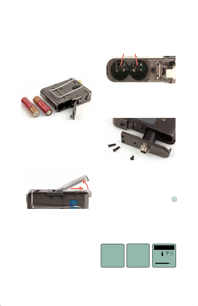
The transmitter is powered by two
AA batteries. Lithium batteries are
recommended for longest life.
The battery status circuitry compensates for the difference in voltage
drop between alkaline and lithium
batteries across their usable life, so
it’s important to select the correct
battery type in the menu.
Because rechargeable batteries
run down quite abruptly, using the
Power LED to verify battery status
will not be reliable. However, it is
possible to track battery status using the battery timer function available in the receiver.
Push outward on the battery compartment door and lift it to open.
The battery contacts can be
cleaned with alcohol and a cotton
swab, or a clean pencil eraser. Be
sure not to leave any remnants of
the cotton swab or eraser crumbs
inside the compartment.
Spring contacts
Optional Battery Eliminator
The transmitter can be powered
by external DC using the optional
LTBATELIM power supply adapter.
Slide door outward,
then lift up to open
Insert the batteries according to the
markings on the back of the housing.
If the batteries are inserted incorrectly, the door will close but the unit
will not operate.
LECTROSONICS, INC.4
Powering On/Off
Powering On
in Operating Mode
Press and hold the Power Button
for several seconds until a counter on the LCD progresses from 1
through 3.
When you release the button, the
unit will be operational with the
RF output turned on and the Main
Window displayed.
Hold
for
Rf On
...3
Page 5

470.100
-40
-20
+0
DCHT
Use
ProgSw
to power
off.
Powering On in Standby Mode
A brief press of the power
button
, and releasing it before
the counter has reached 3, will
turn the unit on with the RF output
turned off. In this Standby Mode the
menus can be browsed to make settings and adjustments without the
risk of interfering with other wireless
systems nearby.
RF indicator
blinks
Hold
for
Rf On
...1
Release
Power
Button
before the
counter
reaches
3 to enter
Standby
Mode
After settings and adjustments are
made, press the power button again
to turn the unit off.
Powering Off
Powering
O . . .
1
(if it is configured for this function).
If the power button is released, or
the top panel switch is turned back
on again before the countdown
is completed, the unit will remain
turned on and the LCD will return to
the same screen or menu that was
displayed previously.
To turn the unit off,
hold the Power Button
in and wait for the
countdown, or use the
programmable switch
Power Button Menu
Entering the Power Menu
When the unit is turned on and the
Main Window is displayed, press
the power button
with various setting and functions.
Use the
and arrow buttons to
highlight menu items. Then press
MENU/SEL to execute the item or
enter a setup screen. The following
options are available:
• Resume - returns to the previous mode and screen
• Pwr Off - turns the unit off
irrevocably. Press either the
power button
SEL to turn the unit off. If the
Programmable Switch has
been set to control the power,
a message will be displayed
prompting you to use the
switch to turn the power off.
Resume
Pwr Off
Rf On?
AutoOn?
Refer to the ProgSw settings on
the following pages to configure the
programmable switch
• Rf On? - enters a screen to enable the operating or standby
modes
• AutoOn? - If external power
to open a menu
or MENU/
Message
appears
if ProgSw
is set to
control
power
or batteries fail while the unit
NOTE: If the programmable
switch is in the OFF position,
power can still be turned on
with the power button.
is transmitting, the unit will
automatically turn back on
after power is restored or fresh
batteries are installed (does
not work in Standby mode).
• Backlit - adjusts the duration of
the LCD back light to 30 seconds, 5 minutes or to remain
on
• LED Off - enters a screen with
options to turn the control
panel LEDs on or off
• About - displays model number
www.lectrosonics.com 5
and firmware version
Page 6

LCD Menu Map
Use arrow buttons
SEL button to
Gain
SEL
2
BACK
SEL
BACK
SEL
BACK
SEL
BACK
SEL
BACK
SEL
BACK
SEL
BACK
SEL
BACK
1
22
20
Freq.
470.675
SEL
GetFrq
SendFrq
SEL
SEL
GetAll
SEL
SendAll
SEL
Name...
Flex...
SEL
ProgSW
(none)
Select option with arrow buttons
Mute
Power
Rolloff
Select value with arrow buttons
50 Hz
StMode
Select option with arrow buttons
Indep
Linked
Phase
Select option with arrow buttons
Analog
AES
InpCfg1
Select setting with
Line In
arrow buttons
Gain
Freq.
M2R...
ProgSw
Rolloff
StMode
InType
InpCfg1
Gain
select channel
(gain value
highlighted)
2
1
to select value
22
20
Level meter at bottom of screen
Press MENU/SEL to highlight MHz or kHz
Select value with arrow buttons
GetFreq.
BACK
BACK
BACK
BACK
BACK
BACK
Press UP arrow button to begin sync
Sync
SendFreq
Press UP arrow button to begin sync
Sync
GetAll
Press UP arrow button to begin sync
Sync
SendAll
Press UP arrow button to begin sync
Sync
Name...
SEL
NameTx
NameCh1
BACK
NameCh2
Flex...
SendTx
Select option with arrow buttons
SendCh1
SendCh2
NameTx
NOTE: When
StMode is set
to Linked, a
single gain
value field will
be shown
Select character with arrow buttons
Press MENU/SEL to confirm and move cursor to next
position; 8 characters available
SendTx
SEL
BACK
Sync
Settings will be
stored when the
BACK button is
pressed.
InpCfg2
BatType
BatTime
Remote
TxPower
Locked?
Default
InpCfg2
SEL
BACK
SEL
BACK
SEL
BACK
SEL
BACK
SEL
BACK
SEL
BACK
SEL
BACK
Select setting with
Oth Lav
arrow buttons
BatType
Select option with arrow buttons
Alk.
Lith.
Bat 5:41
Reset?
Select option with arrow buttons
No
Yes
Remote
Select option with arrow buttons
Enable
Ignore
TxPower
10 mW
Select option with arrow buttons
25 mW
50 mW
Locked?
Select option with arrow buttons
Yes
No
Default
Settings
Select option with arrow buttons
No
Yes
LECTROSONICS, INC.6
Page 7

Main Menu and Setup Screen Details
Entering the Main Menu
The LCD and keypad interface makes it easy to browse the menus and make
the selections for the setup you need. When the unit is powered up in either
the operating or the standby mode, press MENU/SEL on the keypad to enter
a menu structure on the LCD. Use the
menu item. Then press the MENU/SEL button to enter the setup screen.
and arrow buttons to select the
Gain
Gain
Freq.
ProgSw
Rolloff
The prompt in the upper right corner may
display one or both arrows, depending upon
what adjustment can be made. If the changes
are locked, a small padlock symbol will appear.
-40
25
-20
0
Main Window Indicators
The Main Window displays the current settings, status, audio level and battery status.
Programmable
Switch Function
DCHT
MUTE
470.100
Frequency (MHz)
-40
-20
Audio level
If the programmable switch function is set for MUTE, the Main Window will
indicate that the function is enabled.
Mute function
enabled but
not active
DCHT
MUTE
470.100
Operating
mode
Battery status
+0
-40
-20
+0
www.lectrosonics.com 7
Page 8

When the switch is turned on, the mute icon appearance will change and the
word MUTE will blink at the bottom of the display. The -10 LED on the top
panel will also glow solid red.
Mute function
enabled and active
DCHT
MUTE
470.100
Main Window will
blink the word
MUTE when the
audio is muted
<–MUTE–>
Connecting the Signal Source
Microphones, line level audio sources and instruments can be used with the
transmitter. Refer to the section entitled Input Connections for details on the
correct wiring for line level sources and microphones to take full advantage of
the Servo Bias circuitry.
Adjusting the Input Gain for Analog Inputs
For analog gain adjustment, two multi-color LEDs on the top panel, one for
each channel, provide a visual indication of the audio signal level entering
the transmitter. The LEDs will glow either red or green to indicate modulation
levels as shown in the following table.
Signal Level CH1 CH2
Less than -20 dB
-20 dB to +0 dB
+0 dB and greater
Off Off
Green Green
Red Green
NOTE: This procedure is used for analog inputs only. AES digital input
is factory set at the industry standard level. The LEDs on the top panel
will glow blue when the audio level reaches about -40 FS.
It is best to go through the following procedure with the transmitter in the
standby mode so that no audio will enter the sound system or recorder during
adjustment.
1) With fresh batteries in the transmitter, power the unit on in the standby
mode (see previous section Powering On in Standby Mode).
2) Navigate to the Gain setup screen.
Gain
Freq.
ProgSw
Rolloff
LECTROSONICS, INC.8
Gain
25
-40
-20
Setup screen in
Linked mode
Gain
20
0
-40
Setup screen in
Independent mode
-20
21
25
0
Page 9

3) Position a microphone the way it will be used in actual operation and
have the user speak or sing at the loudest level that occur during use, or
set the output level of the audio device to the maximum level that will be
used.
4) Use the and arrow buttons to adjust the gain until the LED glows
green most or all of the time, and flicker red during the loudest peaks.
5) Turn the recorder or sound system gain down before setting the transmitter to the normal operating mode and enabling the audio output.
6) If the audio output level of the receiver is too high or low, use only the
controls on the receiver to make adjustments. Always leave the transmitter gain adjustment set according to these instructions, and do not
change it to adjust the audio output level of the receiver.
Selecting Frequency
The setup screen for frequency selection offers two ways to browse the available frequencies.
Gain
Freq.
Freq.
Freq.
ProgSw
494.500
494.500
Rolloff
Press the MENU/SEL button to select each field. Use the and arrow buttons to adjust the frequency. Each field will step through the available frequencies in a different increment.
NOTE: When the frequency is higlighted, hold down the MENU/SEL
button to increase or decrease frequency in higher increments.
Selecting Programmable Switch Functions
The programmable switch on the top panel can be configured using the menu
to provide several functions:
• (none) - disables the switch
• Mute - mutes the audio when switched on; LCD will blink a message and
-10 LED will glow solid red.
• Power - turns the power on and off
Gain
Freq.
ProgSw
Rolloff
ProgSw
(none)
Mute
Power
Use the and
arrow buttons to
select the desired
function or disable
the switch
NOTE: The programmable switch will continue to operate whether or
not keypad changes are locked.
www.lectrosonics.com 9
Page 10

Selecting the Low Frequency Roll-off
The low frequency audio roll-off is adjustable to optimize performance
for ambient noise conditions or personal preference.
Low frequency audio content may be desirable or distracting, so the
point at which the roll-off takes place can be set at 20, 35, 50, 70, 100,
120 and 150 Hz.
Gain
Freq.
ProgSw
Rolloff
Rolloff
70 Hz
Setup screen in
Linked mode
Rolloff
21
70
70
Hz
Hz
Setup screen in
Independent mode
Selecting StMode (stereo mode)
The two channels can be set to Indep (independent) or Linked. Indep allows
the gain to be adjusted separately on each channel. Linked employs the gain
adjustment to both channels.
M2R...
StMode
ProgSw
Rolloff
StMode
Indep
Linked
Selecting Input Type
AES digital or analog audio input is selected with the InType menu item. With
the AES selected, there are no additional settings needed for the input. Analog input configuration is set with the InpCfg1 and InpCfg2 menu items.
InType
InpCfg1
InpCfg2
BatType
LECTROSONICS, INC.10
InType
Analog
AES
Page 11

Selecting Input Configuration
When the input type is set to Analog, InpCfg1 and InpCfg2 menus are used
to configure the audio input for the respective channels. Use the
arrow buttons to select the input type.
and
InType
InpCfg1
InpCfg1
Line In
InpCfg2
Oth Lav
InpCfg2
BatType
TYPE DESC, BIAS, IMPEDANCE, POLARITY
Line In
Dynamic
DPA
B6
COS-11
MKE 2*
M152*
Oth Lav*
Custom
* Separate listings for these microphones are included for convenience, however, they are all the same configuration.
The Custom option opens a setup screen that provides a variety of settings.
Press SEL to select the custom setup item, then press the
buttons to adjust the setting.
InpCfg2
Custom
MicLoZ
0V Neg
Line level signals up to +24 dBu
Low-Z dynamic microphones
DPA lavaliere; 4V, Mid-Z, (+)
Countryman B6; 2V, Low-Z, (+)
Sanken COS-11; 4V, Low-Z, (–)
Sennheiser MKE 2; 4V, Low-Z, (+)
Lectrosonics M152; 4V, Low-Z, (+)
Other lavaliere; 4V, Low-Z, (+)
Manually configurable microphone level
and arrow
Channel select
Input impedance
Bias voltage
Audio polarity
Available settings:
• Input impedance (Z): LOW, MID, HIGH
• Bias voltage: 0V, 2V, 4V
• Audio polarity: + (pos.), – (neg.)
www.lectrosonics.com 11
Page 12

LIMITED ONE YEAR WARRANTY
The equipment is warranted for one year from date of purchase against defects in
materials or workmanship provided it was purchased from an authorized dealer. This
warranty does not cover equipment which has been abused or damaged by careless
handling or shipping. This warranty does not apply to used or demonstrator equipment.
Should any defect develop, Lectrosonics, Inc. will, at our option, repair or replace any
defective parts without charge for either parts or labor. If Lectrosonics, Inc. cannot
correct the defect in your equipment, it will be replaced at no charge with a similar new
item. Lectrosonics, Inc. will pay for the cost of returning your equipment to you.
This warranty applies only to items returned to Lectrosonics, Inc. or an authorized
dealer, shipping costs prepaid, within one year from the date of purchase.
This Limited Warranty is governed by the laws of the State of New Mexico. It states the
entire liablility of Lectrosonics Inc. and the entire remedy of the purchaser for any
breach of warranty as outlined above. NEITHER LECTROSONICS, INC. NOR
ANYONE INVOLVED IN THE PRODUCTION OR DELIVERY OF THE EQUIPMENT
SHALL BE LIABLE FOR ANY INDIRECT, SPECIAL, PUNITIVE, CONSEQUENTIAL,
OR INCIDENTAL DAMAGES ARISING OUT OF THE USE OR INABILITY TO USE
THIS EQUIPMENT EVEN IF LECTROSONICS, INC. HAS BEEN ADVISED OF THE
POSSIBILITY OF SUCH DAMAGES. IN NO EVENT SHALL THE LIABILITY OF
LECTROSONICS, INC. EXCEED THE PURCHASE PRICE OF ANY DEFECTIVE
EQUIPMENT.
This warranty gives you specific legal rights. You may have additional legal rights which
vary from state to state.
 Loading...