

Page 1
DCHT
Digital Transmitter
DCHT, DCHT/E01
INSTRUCTION MANUAL
Quick Start Steps
1) Install good batteries and turn power on (see pages
5 and 7).
2) Set compatibility mode to match the receiver (see
page 11).
3) Connect signal source, select input type and adjust
input gain for optimum modulation level (see page
10).
4) Set or sync frequency to match receiver (see page
11, 12). Also see receiver manual for scanning procedure.
5) Set encryption key type and sync with receiver (see
page 13).
6) Set programmable switch to desired function (see
page 13).
7) Verify RF and audio signals are present at the
receiver (see receiver manual).
Fill in for your records:
Serial Number:
Purchase Date:
WARNING: Moisture, including talent’s sweat,
will damage the transmitter. Wrap the DCHT
in a plastic bag or other protection to avoid
damage.
Rio Rancho, NM, USA
www.lectrosonics.com
Page 2

DCHT, DCHT/E01
Table of Contents
Quick Start Steps ................................................................ 1
Introduction ........................................................................... 3
General Technical Description ........................................... 3
DSP-controlled Input Limiter ............................................... 3
Encryption ........................................................................... 3
Features and Functions ....................................................... 4
Optional Battery Eliminator ................................................. 4
Whip Antennas .................................................................... 4
Battery Status LED Indicator .............................................. 5
Belt Clips ............................................................................. 5
IR (infrared) Port ................................................................. 5
Status LED .......................................................................... 5
Connecting the Signal Source ............................................ 5
Battery Installation ............................................................... 5
DCHT, DCHT/E01 Block Diagram ....................................... 6
Powering On and Off ............................................................ 7
Powering On in Operating Mode ......................................... 7
Powering On in Standby Mode ........................................... 7
Powering Off ....................................................................... 7
Main Menu and Setup Screen Details ................................. 7
Entering the Main Menu ...................................................... 7
Main Window Indicators ..................................................... 7
LCDMenu Map ....................................................................... 8
Input Menu .......................................................................... 10
Adjusting the Input Gain for Analog Inputs ......................... 10
Selecting the Low Frequency Roll-off ................................. 10
Selecting StMode (stereo mode) ........................................ 10
Selecting Input Type ............................................................ 10
Selecting Input Configuration .............................................. 10
Xmit Menu ............................................................................. 11
Selecting Frequency ........................................................... 11
Selecting Transmitter Output Power .................................... 11
Selecting Receiver Compatibility Mode .............................. 11
Turning Rf On/Off ................................................................ 11
Selecting M2R Receiver Functions ..................................... 12
GetFrq ................................................................................. 12
SendFrq .............................................................................. 12
GetAll .................................................................................. 12
SendAll ................................................................................ 12
Name... ................................................................................ 12
Flex ..................................................................................... 12
Key Menu ............................................................................... 13
Encryption Key Management .............................................. 13
KeyType .............................................................................. 13
MakeKey ............................................................................. 13
WipeKey .............................................................................. 13
SendKey .............................................................................. 13
Setup Menu ........................................................................... 13
Selecting AutoOn Feature ................................................... 13
Selecting Programmable Switch Functions......................... 13
Enable/Disable Remote Control Function ........................... 14
Selecting Battery Type ........................................................ 14
Locking/Unlocking Changes to Settings.............................. 14
Selecting Backlit Time ......................................................... 14
Turning LEDs Off/On ........................................................... 14
Restoring Default Settings .................................................. 14
About ..................................................................................... 14
Wireless Designer Software ............................................... 15
Firmware Update Instructions ............................................. 15
Specifications ....................................................................... 15
Input Connections ............................................................... 16
Microphone Cable Termination
for Non-Lectrosonics Microphones ............................. 17
LectroRM ............................................................................... 18
Accessories .......................................................................... 20
Troubleshooting .................................................................... 21
Service and Repair ............................................................... 22
Returning Units for Repair .................................................. 22
2
LECTROSONICS, INC.
Page 3

Digital Transmitter
Introduction
The DCHT, DCHT/E01 transmitter is designed to work
with a companion receiver (such as the Lectrosonics
DCHR or M2R, part of digital camera hop systems)
as an audio relay between an audio production bag
or cart and a camera or other audio device. The 6-pin
input jack accepts two mic or line level analog signals or
AES digital signals from external sources with a variety
of adapter cables. Analog inputs can be linked for the
same gain when used with a stereo source, or operate
independently with individual settings.
This fourth generation digital design features specially
developed, high efficiency digital circuitry for extended
operating time on two AA batteries. The transmitter can
tune in 25 kHz steps across the UHF television band
from 470.100 to 607.950 MHz (E01 frequency range
is 470.100 to 614.375 MHz), with a selectable output
power of 10, 25 or 50 mW.
Studio quality audio performance is assured by high
quality components in the preamp, wide range input
gain adjustment and DSP-controlled limiting for analog
sources, and settings are included for any lavaliere
microphone, dynamic microphones, line level inputs,
and AES digital inputs. Input gain is adjustable over a
51 dB range in 1 dB steps to allow a precise match to
the input signal level, to maximize dynamic range and
signal to noise ratio.
A separate switch is provided on the top panel that can
be configured as mute, power or bypassed.
The housing is constructed of solid machined aluminum
for lasting ruggedness. The exterior is finished with an
ultra hard, dark electroless nickel finish called ebENi.
Firmware updates are made through a side panel
microB USB port.
General Technical
Description
DSP-controlled Input Limiter
For analog sources, the transmitter employs a DSPcontrolled analog audio limiter prior to the analog-todigital converter. The limiter has a range greater than
30 dB for excellent overload protection. A dual release
envelope makes the limiter acoustically transparent
while maintaining low distortion. It can be thought of as
two limiters in series, connected as a fast attack and
release limiter followed by a slow attack and release
limiter. The limiter recovers quickly from brief transients,
so that its action is hidden from the listener, but recovers slowly from sustained high levels to keep audio distortion low and preserve short term dynamic changes in
the audio level.
Encryption
When transmitting audio, there are situations where
privacy is essential, such as during professional sporting events, in court rooms or private meetings. For
instances where your audio transmission needs to be
kept secure, without sacrificing audio quality, Lectrosonics implements AES256 encryption in our digital
wireless microphone systems. High entropy encryption
keys are first created by one of the units in the system.
The key is then synced with another encryption-capable
unit, via the IR port. The audio will be encrypted and
can only be decoded if both the transmitter and receiver
have the matching encryption key. If you are trying to
transmit an audio signal and keys do not match, all that
will be heard is silence.
Canada ISED Notice
This device operates on a no-protection, no-interference basis. Should the user seek to obtain
protection from other radio services operating in the same TV bands, a radio licence is required.
For further details, consult Innovation, Science and Economic Development Canada’s document
Client Procedures Circular CPC-2-1-28, Voluntary Licensing of Licence-Exempt_Low-Power
Radio Apparatus in the TV bands.
Rio Rancho, NM
3
Page 4
DCHT, DCHT/E01
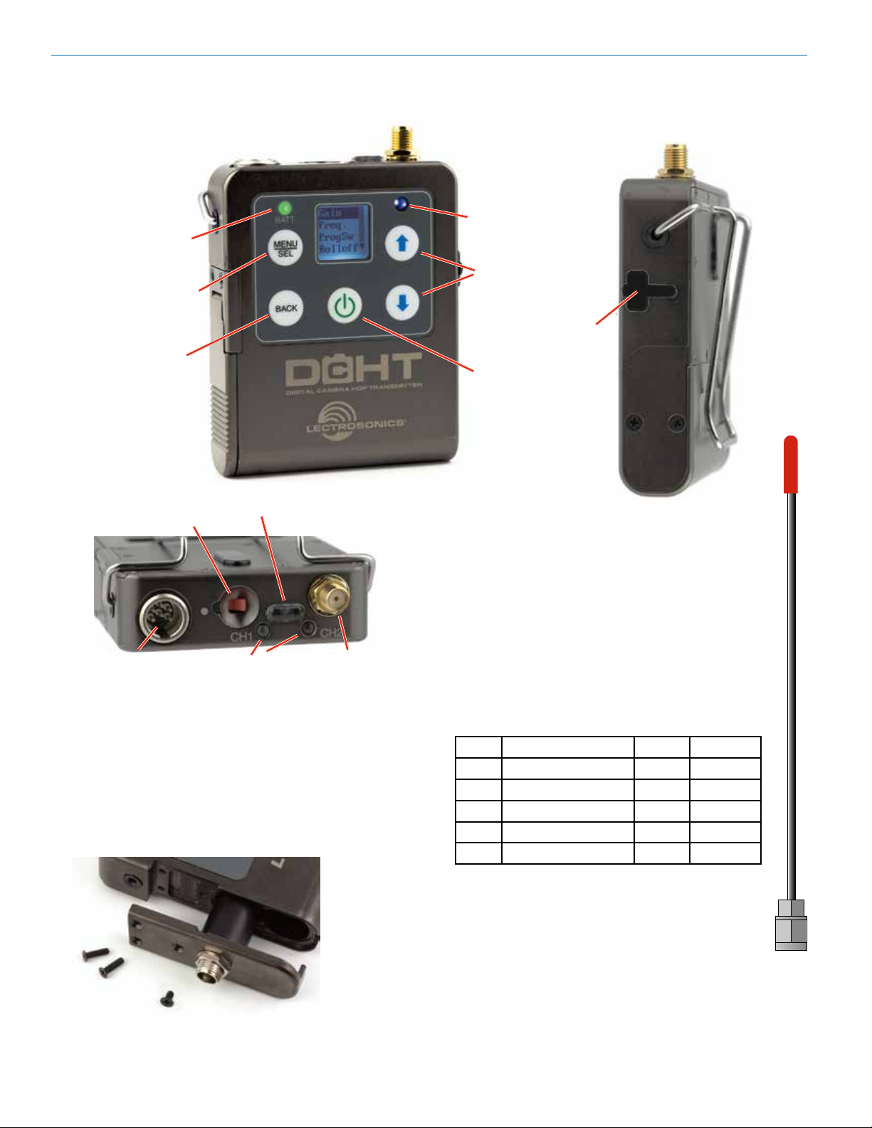
Features and Functions
Battery
status LED
Enter menu/Select item
Return to
previous screen
Status Ready LED
Menu navigation
USB Port
Power
Programmable
function switch
Audio
input
jack
Bi-directional IR port
Modulation
indicators*
Antenna
port
Optional Battery Eliminator
The transmitter can be powered by external DC using
the optional LTBATELIM power supply adapter. The
battery door is replaced by the adapter with a simple
procedure. The adapter provides a locking coaxial connector and a variety of power cords and connectors are
available.
Whip Antennas
Because the transmitter tunes across such a
broad frequency range, it is best to use the appropriate antenna for maximum operation. Two
antennas are included with the transmitter, and
are shipped from the factory pre-cut and fully
assembled. Each antenna covers three blocks.
Refer to the chart below to determine which antenna matches the operating frequency you will
be using.
Frequency Cap
Block Range MHz Color Antenna
470 470.100 - 495.600 Black AMM19
19 486.400 - 511.900 Black AMM19
20 512.000 - 537.500 Black AMM19
21 537.600 - 563.100 Red AMM22
22 563.200 - 588.700 Red AMM22
23 588.800 - 607.950 Red AMM22
4
LECTROSONICS, INC.
Page 5
Digital Transmitter
Battery Status LED Indicator
The Power/Function LED on the top panel will mirror
the keypad LED unless the programmable switch is set
to Mute, and the switch is turned on.
Alkaline, lithium or rechargeable batteries can be used
to power the transmitter. The type of batteries in use are
selectable in a menu on the LCD.
When alkaline or lithium batteries are being used, the
LED labeled BATT on the keypad glows green when the
batteries are good. The color changes to red at a midpoint of the runtime. When the LED begins to blink red,
there will be only a few minutes of operation remaining.
The exact point at which the LEDs turn red will vary
with battery brand and condition, temperature and
power consumption. The LEDs are intended to simply
catch your attention, not to be an exact indicator of
remaining time.
A weak battery will sometimes cause the Power LED to
glow green immediately after the transmitter is turned
on, but it will soon discharge to the point where it will
turn red or the unit will turn off completely.
Rechargeable batteries give little or no warning when
they are depleted. If you wish to use these batteries
in the transmitter, the most accurate way to determine
runtime status is by testing the time provided by a particular battery brand and type, then using the BatTime
function to determine remaining runtime.
NOTE: Refer to the Main Menu and Setup section
for BatTime details.
Belt Clips
The wire belt clip may be removed by pulling the ends
out of the holes in the sides of the case. Be sure to
have a firm grip to avoid scratching the surface of the
housing.
An optional spring-loaded, hinged belt clip (model number BCSLEBN) is also available. This clip is attached by
removing the plastic hole cap on the back of the housing and mounting the clip with the supplied screw.
IR (infrared) Port
The IR port is available on the top of the transmitter for
quick setup using a receiver with this function available.
IR Sync will transfer the settings for frequency from the
receiver to the transmitter.
Status LED
Blue LED indicates ready (transmitting) status.
Connecting the Signal Source
Microphones, line level audio and digital sources can be
used with the transmitter. Refer to the section entitled
Input Connections for details on the correct wiring for
line level sources and microphones to take full advantage of the Servo Bias circuitry.
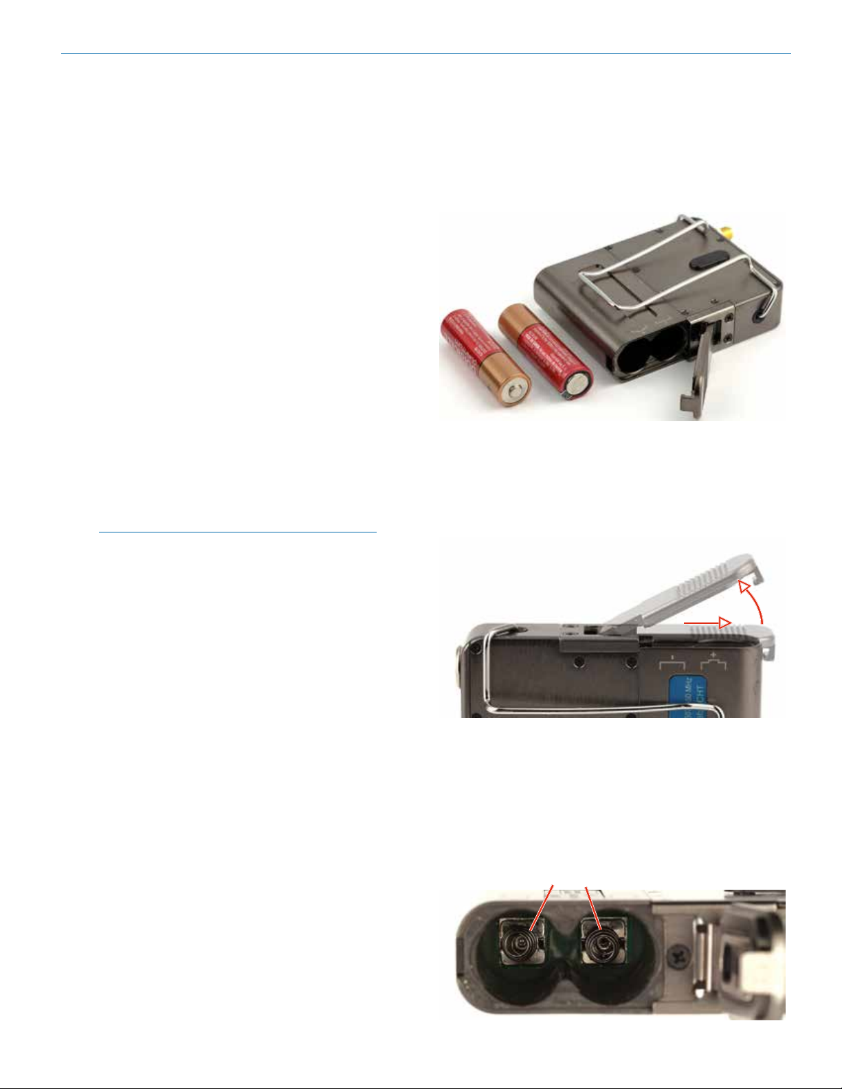
Battery Installation
The transmitter is powered by two AA batteries. Lithium
batteries are recommended for longest life.
The battery status circuitry compensates for the differ-
ence in voltage drop between alkaline and lithium bat-
teries across their usable life, so it’s important to select
the correct battery type in the menu.
Because rechargeable batteries run down quite abrupt-
ly, using the Power LED to verify battery status will not
be reliable. However, it is possible to track battery status
using the battery timer function available in the receiver.
Push outward on the battery compartment door and lift
it to open.
Slide door outward,
then lift up to open
Insert the batteries according to the markings on the
back of the housing.
If the batteries are inserted incorrectly, the door may
close but the unit will not operate.
The battery contacts can be cleaned with alcohol and
a cotton swab, or a clean pencil eraser. Be sure not
to leave any remnants of the cotton swab or eraser
crumbs inside the compartment.
Spring contacts
Rio Rancho, NM
5
Page 6
DCHT, DCHT/E01
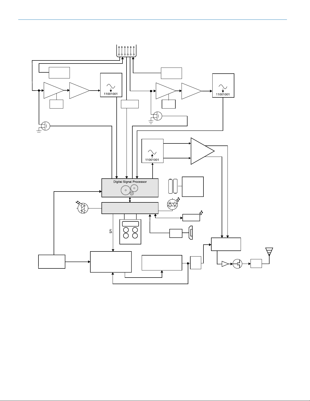
Input
DCHT, DCHT/E01 Block Diagram
CHANNEL 1
Input
Preamp
Shunt
Limiter
Servo Bias
Supply
Gain
Adj
Bias Voltage
0, 2 or 3.6V
HI/Lo
Pass
Filter
Limiter Control
Converter
Audio
I2S
A-D
Jack
123456
Rate
Converter
CHANNEL 2 (analog/digital selectable)
Shunt
Limiter
Input
Preamp
Servo Bias
Supply
Gain
Adj
Limiter Control
Bias Voltage
0, 2 or 3.6V
HI/Lo
Pass
Filter
Audio
A-D
Converter
I2S
DSP Clock
Oscillator
VCTCXO
36.864 MHz
Status Ready
PLL Ref
Phase Locked Loop
Microprocessor
Keypad
D-A Converter
I2S
Control
Baseband
Firmware
Update
Voltage Controlled
Oscillator
I + Q
Signals
(2) AA
Batteries
UART
Switching
Power
LED
Tricolor
IR Port
Power
Supply
Low
Pass
Filter
Low
pass
lters
USB
Jack
IQ Modulator
Buer
Final
Amplier
Filters
6
LECTROSONICS, INC.
Page 7
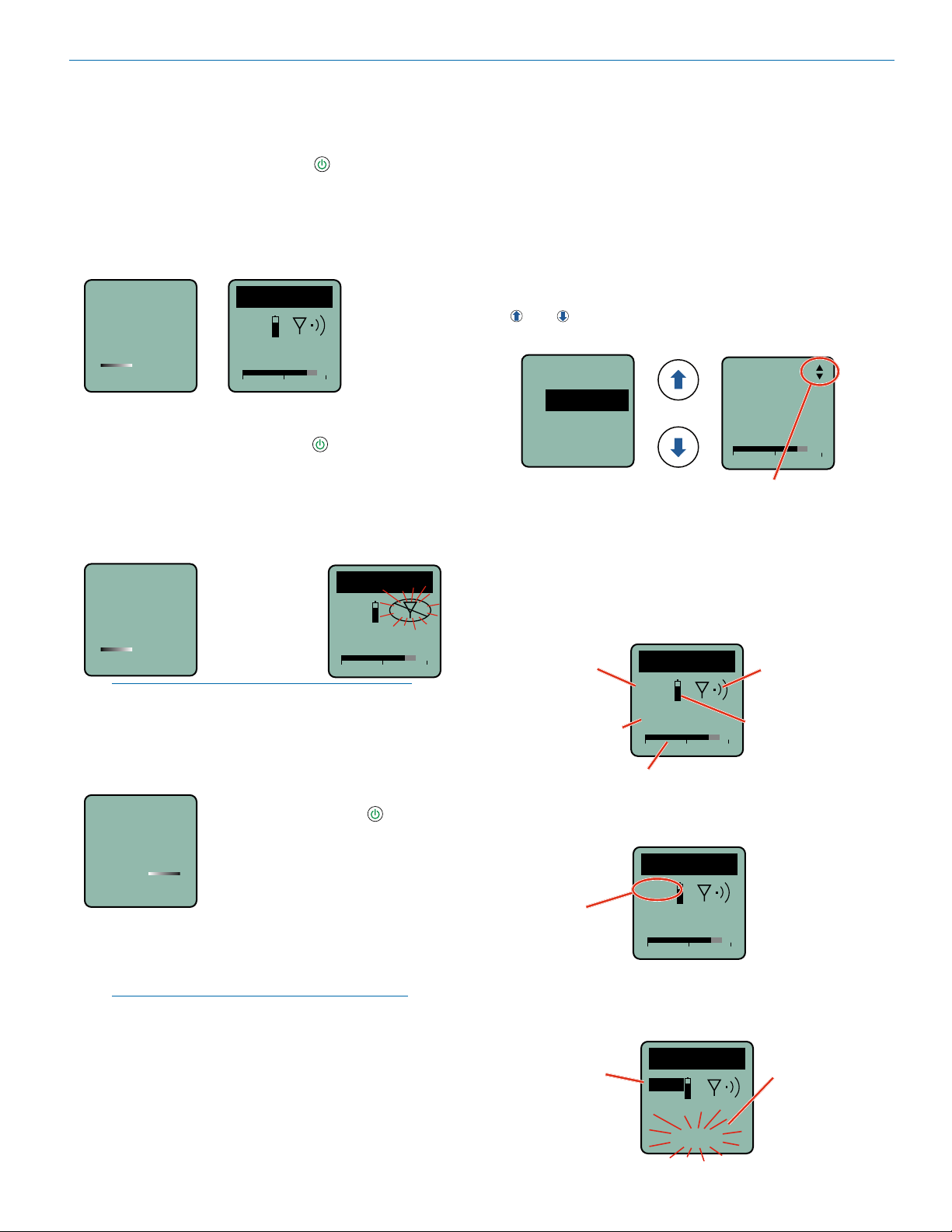
Powering On and Off
Digital Transmitter
power button.
Powering On in Operating Mode
Press and hold the Power Button for a few seconds
until the progress bar on the LCD finishes.
When you release the button, the unit will be operational with the RF output turned on and the Main Window
displayed. You can also use the programming switch if it
is configured for this function.
Hold
for
Rf On
DCHT
MUTE
470.100
-40
-20
+0
Powering On in Standby Mode
A brief press of the power button , and releasing it
before the progress bar finishes, will turn the unit on
with the RF output turned off. In this Standby Mode the
menus can be browsed to make settings and adjustments without the risk of interfering with other wireless
systems nearby.
RF indicator blinks
Hold
for
Rf On
NOTE: After settings and adjustments are made,
press the power button again to turn the unit off or
navigate to menu item Xmit, RFOn? to choose to
begin transmitting.
Release
Power Button
before the bar
progresses to
enter Standby
Mode
DCHT
470.100
-40
-20
+0
Main Menu and Setup
Screen Details
Entering the Main Menu
The LCD and keypad interface makes it easy to browse
the menus and make the selections for the setup you
need. When the unit is powered up in either the operating or the standby mode, press MENU/SEL on the
keypad to enter a menu structure on the LCD. Use the
and arrow buttons to select the menu item. Then
press the MENU/SEL button to enter the setup screen.
Input...
Gain
Rolloff
StMode
The prompt in the upper right corner may
display one or both arrows, depending upon
what adjustment can be made. If the changes
are locked, a small padlock symbol will appear.
Main Window Indicators
The Main Window displays the current settings, status,
audio level and battery status.
Programmable
Switch Function
Frequency (MHz)
DCHT
MUTE
470.100
-40
-20
Gain
-40
Battery status
+0
25
-20
0
Operating
mode
(Transmit or
Standby)
Powering Off
To turn the unit off, press and hold
Powering
O...
the top panel switch is turned back on again before the
progress bar finishes, the unit will remain turned on and
the LCD will return to the same screen or menu that
was displayed previously.
NOTE: If the programmable switch is in the OFF
position, power can still be turned on with the
Rio Rancho, NM
hold the Power Button for a few
seconds and wait for the progress
bar to finish, or use the programmable switch (if it is configured for
this function).
If the power button is released, or
Audio level
If the programmable switch function is set for MUTE,
the Main Window will indicate that the function is enabled.
Mute function
enabled but
not active
DCHT
MUTE
470.100
-40
-20
+0
When the switch is turned on, the mute icon appearance will change and the word MUTE will blink at the
bottom of the display. The -10 LED on the top panel will
also glow solid red.
Mute function
enabled and active
DCHT
MUTE
470.100
Main Window will
blink the word
MUTE when the
audio is muted
<–MUTE–>
7
Page 8
DCHT, DCHT/E01
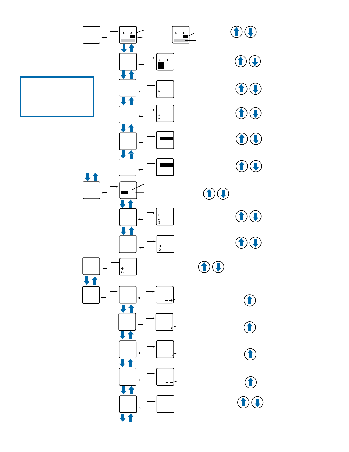
Use arrow buttons
SEL button to
LCD
Menu Map
Settings will be stored
when the BACK button
is pressed.
Input...
Xmit...
SEL
BACK
SEL
BACK
Gain
1
22
20
Rolloff
StMode
InType
InpCfg1
InpCfg2
Freq.
470.675
Grp 1
Gain
2
SEL
SEL
SEL
SEL
SEL
select channel
(gain value
highlighted)
Rolloff
1
BACK
Hz Hz
StMode
Indep.
BACK
Linked
InType
Analog
BACK
AES
InpCfg1
Line In
BACK
InpCfg2
Oth Lav
BACK
70 70
2
1
2
Select value with arrow buttons
to select value
22 20
Level meter at bottom of screen
Select option with arrow buttons
Select option with arrow buttons
Select setting with arrow
buttons: PSA, DPA, B6,
COS-11, MKE 2, M152, Oth
Lav, Custom, Line In, Dynamic
Select setting with arrow
buttons: PSA, DPA, B6,
COS-11, MKE 2, M152, Oth
Lav, Custom, Line In, Dynamic
Press MENU/SEL to highlight MHz or kHz or to
select a Frequency Group
Select value with arrow buttons
NOTE: When StMode is set
to Linked, a single gain value
field will be shown
Compat
IR&Key
SEL
SEL
BACK
BACK
Txpower
Rf On?
Compat
Duet
DCHX
SendFrq
SendAll
GetFrq
GetAll
BACK
BACK
TxPower
10 mW
25 mW
50 mW
Rf On?
Yes
No
Select option with arrow buttons
Select option with arrow buttons
SEL
SEL
Select option with arrow buttons
BACK
BACK
BACK
BACK
SendFreq
Sync
SendAll
Sync
GetFreq.
Sync
GetAll
Sync
Press UP arrow button to begin sync
Press UP arrow button to begin sync
Press UP arrow button to begin sync
Press UP arrow button to begin sync
SEL
SEL
SEL
SEL
KeyType
SEL
KeyType
BACK
8
Select option with arrow buttons:
Shared, Standard, Volatile,
Universal
Shared
LECTROSONICS, INC.
Page 9

SEL
BACK
Setup...
SEL
BACK
ProgSw
AutoOn?
SEL
BACK
AutoOn?
Select option with arrow buttons
ProgSw
Mute
Select option with arrow buttons:
(none), TalkBk, Po wer, Mute
Remote
SEL
BACK
Remote
Select option with arrow buttons
SEL
BACK
Locked?
Locked?
Select option with arrow buttons
Backlit
SEL
BACK
Select option with arrow buttons
Backlit
On
30 sec
5 sec
SEL
BACK
LED Off
Select option with arrow buttons
SEL
BACK
Default
Default
Settings
No
Yes
Select option with arrow buttons
LEDs
On
Off
SEL
BACK
Make
Key
SEL
BACK
SendKey
SendKey
Sync
Press UP arrow button to begin sync
WipeKey
SEL
BACK
WipeKey?
No
Yes
Select option
with arrow
buttons
No
Yes
Enable
Ignore
Yes
No
SEL
BACK
NameTx
NameTx
Press MENU/SEL to confirm
and move cursor to next
position; 8 characters available
Select character with
arrow buttons
SEL
BACK
Flex...
Flex...
SendTx
SendCh1
SendCh2
SEL
BACK
SendTx
Sync
Select option with arrow buttons:
SendTx, SendCh1, SendCh2,
SendM12, NameTx, NameCh1,
NameCh2
BatType
SEL
BACK
BatType
Alk.
Lith.
Select option with arrow buttons
NOTE: The key
menu selections
only show
when DCHX
compatibility mode
(encryption) is
selected and a
key type other
than Universal is
selected.
Digital Transmitter
NOTE: Make, Wipe
and Send Key
Menu options are
only available in
Shared, Standard
and Volatile Key
Types. They will not
be displayed in the
menu if Universal
Key Type is chosen.
Rio Rancho, NM
9
Page 10

DCHT, DCHT/E01
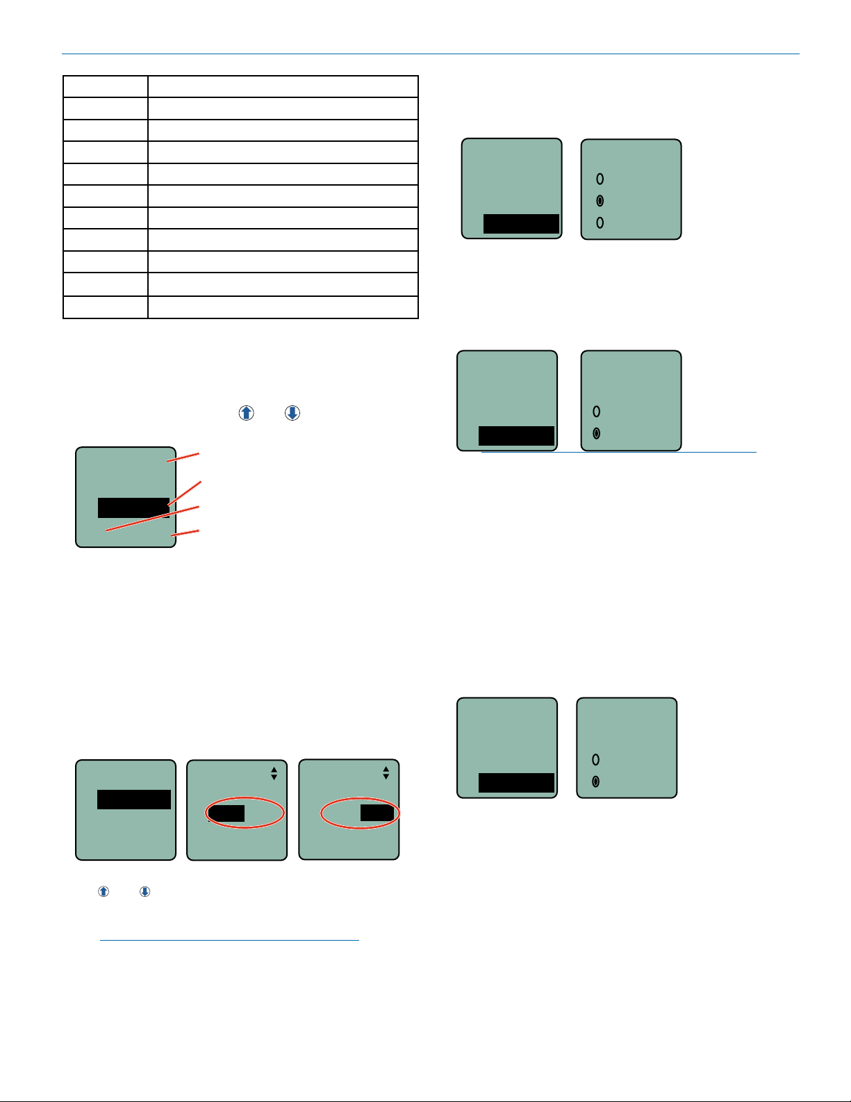
Input Menu
Adjusting the Input Gain for Digital Inputs
For gain adjustment, two multi-color LEDs on the top
panel, one for each channel, provide a visual indication
of the audio signal level entering the transmitter. The
LEDs will glow either red or green to indicate modulation levels.
It is best to go through the following procedure with the
transmitter in the standby mode so that no audio will enter the sound system or recorder during adjustment.
1) With fresh batteries in the transmitter, power the
unit on in the standby mode (see previous section
Powering On in Standby Mode).
2) Navigate to the Gain setup screen.
Input...
Gain
Rolloff
StMode
3) If using a microphone, position it the way it will be
used in actual operation and have the user speak or
sing at the loudest level that occur during use. Or,
set the output level of the source audio device to
the maximum level that will be used.
4) Use the and arrow buttons to adjust the gain
until the LED glows green most or all of the time,
and flicker red during the loudest peaks.
5) Turn the recorder or mixer gain down before setting
the transmitter to the normal operating mode and
enabling the audio output.
6) If the audio output level of the receiver is too high or
low, use only the controls on the receiver to make
adjustments. Always leave the transmitter gain adjustment set according to these instructions, and do
not change it to adjust the audio output level of the
receiver.
7) If the audio source drives the inputs into limiting,
the audio level meter will move all the way to the
right and terminate in a small box with an “L” in it,
indicating limiting. If this happens on anything other
than brief peaks, then the audio gain is set too high.
Gain
Gain
25
-40
-20
Setup screen in
Linked mode
Gain
20
0
-40
Setup screen in
Independent mode
25
-20
Selecting the Low Frequency Roll-off
The low frequency audio roll-off is adjustable to optimize performance for ambient noise conditions or
personal preference.
Low frequency audio content may be desirable or
distracting, so the point at which the roll-off takes place
can be set at 20, 35, 50, 70, 100, 120 and 150 Hz.
Input...
Rolloff
Gain
Rolloff
70 Hz
StMode
Setup screen in
Linked mode
21
0
Selecting StMode (stereo mode)
The two channels can be set to Indep (independent) or
Linked. Indep allows the gain to be adjusted separately
on each channel. Linked employs the gain adjustment
to both channels.
Input...
StMode
Rolloff
21
70
70
Hz
Hz
Setup screen in
Independent mode
Gain
Rolloff
StMode
Indep
Linked
Selecting Input Type
AES digital or analog audio input is selected with the
InType menu item. With the AES selected, there are no
additional settings needed for the input. Analog input
configuration is set with the InpCfg1 and InpCfg2
menu items.
Input...
InType
InType
InpCfg1
InpCfg2
Analog
AES
Selecting Input Configuration
When the input type is set to Analog, InpCfg1 and
InpCfg2 menus are used to configure the audio input
for the respective channels. Use the and arrow
buttons to select the input type.
10
-40
25
-20
Input...
L
0
InType
InpCfg1
InpCfg1
Line In
InpCfg2
Oth Lav
InpCfg2
LECTROSONICS, INC.
Page 11
Digital Transmitter
TYPE DESC, BIAS, IMPEDANCE, POLARITY
Line In
Dynamic
PSA
DPA
B6
COS-11
MKE 2*
M152*
Oth Lav*
Custom
* Separate listings for these microphones are included
for convenience, however, they are all the same configuration.
The Custom option opens a setup screen that provides
a variety of settings. Press SEL to select the custom
setup item, then press the
adjust the setting.
InpCfg2
Custom
MicLoZ
0V Neg
Line level signals up to +24 dBu
Low-Z dynamic microphones
Point Source Audio lav microphones
DPA lavaliere; 4V, Mid-Z, (+)
Countryman B6; 2V, Low-Z, (+)
Sanken COS-11; 4V, Low-Z, (–)
Sennheiser MKE 2; 4V, Low-Z, (+)
Lectrosonics M152; 4V, Low-Z, (+)
Other lavaliere; 4V, Low-Z, (+)
Manually configurable microphone level
and arrow buttons to
Channel select
Input impedance
Bias voltage
Audio polarity
Selecting Transmitter Output Power
The output power can be set to 10 mW, 25 mW
or 50 mW.
Xmit...
TxPower
Compat
Rf On?
TxPower
10 mW
25 mW
50 mW
Turning Rf On/Off
Turn Rf off to preserve battery power while setting other
transmitter functions. Turn it back on to begin transmitting.
Xmit...
Rf On?
TxPower
Compat
Rf On?
NOTE: When transmitter is off, a brief press of the
Power Button will turn the transmitter on with Rf
off. Use this function to turn Rf on when ready to
transmit.
Ye s
No
Compatibility Mode
Available settings:
• Input impedance (Z): LOW, MID, HIGH
• Bias voltage: 0V, 2V, 4V
• Audio polarity: + (pos.), – (neg.)
Xmit Menu
Selecting Frequency
The setup screen for frequency selection offers multiple
ways to browse the available frequencies.
Xmit...
Freq.
Freq
TxPower
Rf On?
Press the MENU/SEL button to select each field. Use
the and arrow buttons to adjust the frequency.
Each field will step through the available frequencies in
a different increment, or select the Frequency Group.
NOTE: When the frequency is highlighted, hold
down the MENU/SEL button to increase or
decrease frequency in higher increments.
494.500
Grp 4
Freq.
494.500
Grp 4
Selecting Receiver Compatibility Mode
The transmitter can be set to operate with different
receivers:
Duet: M2R digital IEM/IFB receiver
DCHX: DCHR and M2R-X encrypted (FW v3.x)
TopMenu
Input
Xmit
Compat
Compat
Duet
DCHX
Rio Rancho, NM
11
Page 12

DCHT, DCHT/E01
IR&Key Menu
encryption amongst multiple transmitters and receivers, but not as secure as creating a unique key.
GetFrq
Sync to receive (get) frequency from the M2R transmitter via the IR port
SendFrq
Sync to send frequency to the M2R transmitter via the
IR port
GetFrq
Sync
SendFrq
Sync
Press the arrow
button to begin sync
GetAll
Sync to receive (get) all available settings from the M2R
transmitter via the IR port, including the performer’s
name, (or whatever name the user chooses for the
DCHT, DCHT/E01), frequency, mixer settings and limiter settings.
NOTE: The GetAll function is designed for trouble
shooting and allows for settings to be cloned to transfer
to another receiver if there is a problem to be identified. Not all copied settings are available on the DCHT,
DCHT/E01.
SendAll
Sync to send all available settings to the M2R transmitter via the IR port, including the performer’s name, (or
whatever name the user chooses for the DCHT, DCHT/
E01), frequency, mixer settings and limiter settings.
NOTE: The SendAll function is designed for trouble
shooting and allows for settings to be cloned to transfer
to another receiver if there is a problem to be identified.
Not all settings are available on the DCHT, DCHT/E01.
GetAll
Sync
SendAll
Sync
Press the arrow
button to begin sync
NOTE: When the DCHT is set to Universal
Encryption Key, Make Key, Wipe Key and Share
Key will not appear in the menu.
• Shared: There are an unlimited number of shared
keys available. Once generated by the DCHT and
transferred to an encryption capable receiver, the
encryption key is available to be shared (synced) by
the receiver with other encryption capable transmitters/receivers via the IR port.
• Standard: Standard Keys are unique to the DCHT
and there are only 255 key instances available to be
transferred to a receiver.
• Volatile: This one-time only key is the highest level
of encryption security. The Volatile Key exists only
as long as the power in both the DCHT Transmitter
and an encryption capable receiver remains on during a single session. If the receiver is powered off,
but the DCHT has remained turned on, the Volatile
Key must be sent to the receiver again. If the power
is turned off on the DCHT, the entire session concludes and a new Volatile Key must be generated
by the transmitter and sent to the receiver via the IR
port. Similar to Standard Keys, there are only 255
key instances to be transferred to a receiver.
MakeKey
When the transmitter key type is set to Volatile, Standard or Shared, use this menu item to create a unique
key that can be synced with an encryption capable
receiver.
WipeKey
This menu item is only available if there is a key currently on the DCHT that can be deleted. Select Yes to
wipe the current key and enable the DCHT to create a
new key.
Key...
KeyType
MakeKey
WipeKey
WipeKey?
No
Ye s
Encryption Key Management
KeyType
The DCHT has four options for encryption keys:
• Universal: This is the most convenient encryption
option available. All encryption-capable Lectrosonics transmitters and receivers contain the Universal
Key. The key does not have to be generated by
the DCHT. Simply set a Lectrosonics encryptioncapable receiver and the DCHT to Universal, and
the encryption is in place. This allows for convenient
12
SendKey
This menu item (under IR&Key) is only available if Key
Type is set to Volatile, Standard or Shared, and a new
key has been created. Press Menu/Sel to sync the
Encryption key to another transmitter or receiver via the
IR port.
Key...
MakeKey
WipeKey
SendKey
SendKey
Send
LECTROSONICS, INC.
Page 13

Digital Transmitter
Flex List
Name
Name the DCHT, DCHT/E01 to allow easy identification on the M2R FlexList. The following are available for
custom names:
- NameTx: Name the DCHT, DCHT/E01
- NameCh1: Name Channel 1
- NameCh2: Name Channel 2
Use the UP and DOWN arrows to choose which
character you want and then MENU/SEL to move
to next space (there are 8 spaces available for each
name). Press BACK to save.
NOTE: Duplicate names are not allowed in a FlexList.
Be sure to choose unique names for Tx, Ch1 and Ch2.
NameTx
Cursor
DCHT
Sync DCHT, DCHT/E01 information to the M2R FlexList
either as one stereo Channel or individual channels:
- SendTx: Send (sync) all receiver information to
the M2R FlexList as one stereo channel
- SendCh1: Send (sync) Channel 1 unique infor-
mation to the M2R FlexList
- SendCh2: Send (sync) Channel 2 unique infor-
mation to the M2R FlexList
- SendM12: Send (sync) a mono mix of both
channels to the M2R FlexList
Press the and
arrow buttons to select
the desired character,
press MENU/SELECT
to move to next space;
there are 8 spaces
available.
Setup Menu
Selecting AutoOn Feature
If external power is switched off or batteries fail while
the unit is transmitting, the unit will automatically turn
back on after power is restored or fresh batteries are
installed. This function is enabled by selecting Yes in
the menu options.
Setup...
AutoOn?
ProgSw
Remote
NOTE: AutoOn does not work when the transmitter
is in the Standby mode.
Selecting Programmable Switch Functions
The programmable switch on the top panel can be configured using the menu to provide several functions:
• (none) - disables the switch
• Mute - mutes the audio when switched on; LCD will
blink a message
• Power - turns the power on and off
Setup...
AutoOn?
ProgSw
Remote
NOTE: The programmable switch will continue
to operate whether or not keypad changes are
locked.
AutoOn?
No
Ye s
ProgSw
Mute
Press the and
arrow buttons to select
the desired function or
disable the switch
SendTx
Sync
Rio Rancho, NM
SendCh1
Sync
Use the arrow
button to begin sync
Enable/Disable Remote Control Function
The “dweedle tone” remote control is turned on or off
with the Remote menu, setting the transmitter to react
to tones received (Enable) or to Ignore the tones.
Setup...
AutoOn?
ProgSw
Remote
NOTE: Remote control of settings is enabled
using a third party smart phone app named
DCHTRemote, published by New Endian, LLC.
Remote
Enable
Ignore
13
Page 14
DCHT, DCHT/E01
Selecting Battery Type
The voltage drop over the life of different batteries varies by type and brand. Be sure to set the correct battery
type for accurate indications and warnings. The menu
offers alkaline or lithium types.
Setup...
BatType
BatType
Locked?
Backlit
If you are using rechargeable batteries, it is better to
use the timer function on the receiver to monitor the
battery life rather than the indicators on the transmitter.
Rechargeable batteries maintain a fairly constant voltage across the operating time on each charge and stop
working abruptly, so you will have little or no warning as
they reach the end of operation.
Alk.
Lith.
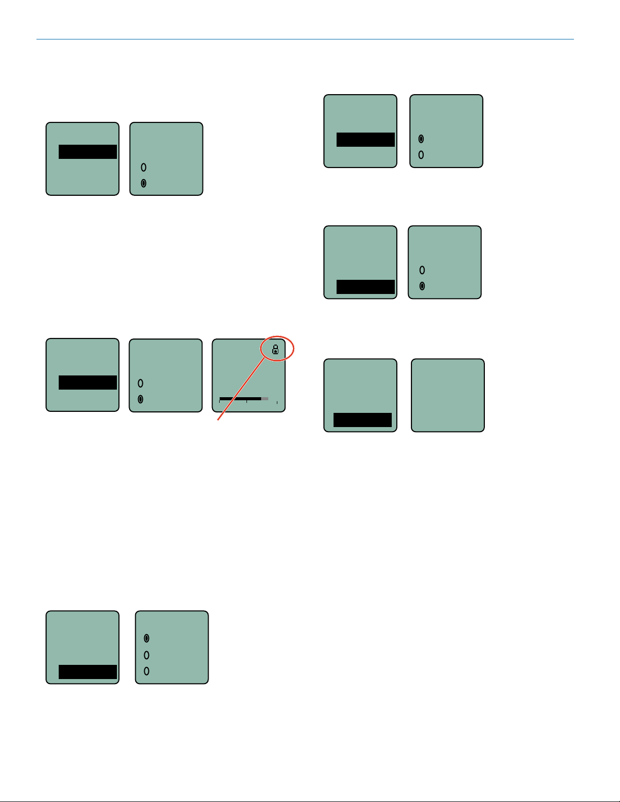
Locking/Unlocking Changes to Settings
Changes to the settings can be locked to prevent inadvertent changes being made.
Setup...
NameTx
Locked?
Backlit
A small padlock symbol will appear on adjustment
Locked?
Ye s
No
screens when changes have been locked.
Gain
-40
25
-20
Turning LEDs Off/On
Options to turn the control panel LEDs on or off.
Setup...
LEDs
Backlit
LED Off
Default
On
Off
Restoring Default Settings
This is used to restore the factory settings.
Setup...
Backlit
LED Off
Default
Default
settings
No
Ye s
About
Displays model number and firmware
version.
TopMenu...
Key...
0
Setup...
About
About
DCHT
V1.15
/1.10
When changes are locked, several controls and actions
can still be used:
• Settings can still be unlocked.
• Menus can still be browsed.
• Programmable switch still works (Mute and On/Off).
• Sync functions are still available (except Get Freq.
and Get All).
Selecting Backlit Time
Adjusts the duration of the LCD back light to 30 seconds, 5 minutes, or to remain on.
Setup...
BatType
Locked?
Backlit
Backlit
On
30 sec
5 sec
14
LECTROSONICS, INC.
Page 15

Digital Transmitter
Firmware Update
Instructions
Firmware updates are made with a file downloaded
from the web site and the DCHT or DCHT/E01 connected via USB, and Wireless Designer software.
The USB port on the transmitter requires a micro-B
male plug on the connecting cable. The other end of the
cable would normally be a USB A-Type male connector to fit the most common type of USB jack used on
computers.
Put the transmitter in UPDATE mode
by simultaneously holding down the
UPDATE
DCHT
V1.10
/1.10
WARNING: Do not connect more than one
Lectrosonics device to your computer while
updating firmware. Wireless Designer may
need to be updated to the current version to
perform a firmware update on recent products
UP and DOWN arrow buttons on the
transmitter control panel while
powering it up.
Refer to Help in Wireless Designer
software for instructions.
Once the Update has completed,
turn off the transmitter, then turn it
back on to verify that the firmware
version on the transmitter LCD
matches the firmware version shown
on the web site. The firmware is the
second LCD display during boot up
sequence.
Specifications
Operating Frequencies:
DCHT 470.100 - 607.950 MHz
DCHT/E01 470.100 - 614.375 MHz
NOTE: It’s the user’s responsibility to select the approved
frequencies for the region where the transmitter is
operating
Frequency Selection Steps: 25 kHz
RF Power Output: Selectable; 10, 25 or 50 mW
Frequency Stability: ± 0.002%
Spurious Radiation:
DCHT Compliant ETSI EN 300 422-1 v1.4.2
DCHT/E01 Compliant ETSI EN 300 422-1 v2.1.2
Digital Modulation: 8PSK
Encryption: AES 256-CTR (per FIPS 197 and FIPS 140-2)
Equivalent Input Noise: –128 dBV
Input Types: • Analog; mic and line level
• AES digital
Input Level (analog) • Mic: Nominal 2 mV to 300 mV, before limiting
Greater than 1V maximum, with limiting
• Line: +24 dBu before limiting
Input Impedance: • Mic: 300 or 4.5 k ohm; selectable
• Line: greater than 100 k ohm
Input Limiter: Dual envelope type; 30 dB range
Gain Control Range: 51 dB in 1 dB steps; digital control
Modulation Indicators: • Bicolor LED indicates modulation of
-20 and 0 dB referenced to full modulation
• LCD bar graph
Frequency Response: 15 Hz – 11.3 kHz, +0, -3 dB
Controls: • Top panel toggle switch; programmable as
power, mute or none (off) function
• Front panel membrane switches with LCD
interface for power on/off and all setup and
configuration controls
Audio Input Jack: Switchcraft 6-pin locking (TA6F)
Antenna: Galvanized steel, flexible wire, SMA connector
Battery: Two AA Lithium recommended
Battery Life: 5 hours; top quality alkaline
Weight: • 5.75 ozs. (163 grams); w/ belt clip and lithium
AA batteries
• 6.40 ozs. (181 grams); w/ belt clip and Duracell
Quantum AA batteries
Overall dimensions: 3.45 x 2.44 x .742 in. (88 x 62 x 19 mm)
Emission Designator: 200KG7E
Rio Rancho, NM
Specifications subject to change without notice
15
Page 16

DCHT, DCHT/E01
Input Connections
The 6-pin input jack accommodates two discrete channels at microphone or line levels. The input connections
are configured as follows:
ANALOG DIGITAL
Pin 1 CH 1 Shield/Gnd AES GND
Pin 2 CH 1 Mic level
Pin 3 CH 1 Line level
Pin 4 CH 2 Mic level AES CH 1
Pin 5 CH 2 Shield/Gnd AES CH 2
Pin 6 CH 2 Line level
5
4
1
6
2
TA6FLX connector
3
viewed from outside
NOTICE: Any microphone wired using pin 2 for elec-
tret bias will NOT work with the DCHT, DCHT/E01 and
MCTA6TA5M2 adapter. For example, see figures 1
and 2 (below) for servobias inputs that will not operate
properly.
Fig. 1
2 VOLT POSITIVE BIAS 2-WIRE ELECTRET
SHIELD
A UDI O
Compatible wiring for microphones such as
Countryman E6 headworn and B6 lavaliere.
3.3 k
Also see Fig. 9
1.5 k
PIN
1
2
3
4
5
4
3
T A5 F
PLUG
1
5
2
Fig. 2
2 VOLT NEGATIVE BIAS 2-WIRE ELECTRET
SHIELD
AUDIO
Compatible wiring for microphones
such as negative bias TRAM models.
NOTE: The resistor value can range from 2k to 4k ohms.
2.7 k
PIN
1
2
1
4
3
5
3
TA5F
PLUG
2
4
5
Refer to the Accessories section of this manual for
details on the available adapter cables.
The mating connector for the DCHT, DCHT/E01 input jack is a Switchcraft TA6FLX 6-pin female (nickel
plated).
NOTE: The Sanken CUB-01 is wired using pin
2 for the bias and will not work with the DCHT,
DCHT/E01 and MCTA6TA5M2 adapter.
Lectrosonics P/N 21932.
AES IEC Type 1 and 2 Wiring (TA6F to XLRF)
Type 1 interface: Type I connections use balanced,
3-conductor, 110-ohm twisted pair cabling with XLR
connectors. Most often used in professional installations
and are considered the standard connector for AES3.
Wire as shown.
Type 2 interface: A 75-ohm unbalanced electrical or
optical interface for consumer electronics applications
(less common). Connect pin 4 to the center pin of the
16
connector. Connect pin 5 to the connector shell. Shield
(pin 1 of the TA6) is unused.
LECTROSONICS, INC.
Page 17

Microphone Cable Termination
0.3"
for Non-Lectrosonics Microphones
TA6F Connector Assembly
Mic Cable Stripping Instructions
1
5
6
4
2
Digital Transmitter
3
VIEWED FROM
0.15"
OUTSIDE
Crimping to Shield and Insulation
Strip and position the cable so that the clamp
can be crimped to contact both the mic cable
shield and the insulation. The shield contact
reduces noise with some microphones and the
insulation clamp increases ruggedness.
Rio Rancho, NM
Shield
Crimp these
fingers to
contact the
shield
Insulation
Crimp these
fingers to
clamp the
insulation
17
Page 18

DCHT, DCHT/E01
DCHTRemote
By New Endian LLC
DCHTRemote is a mobile application for iOS operating systems to remotely control the Lectrosonics DCHT
Transmitter.
The app remotely changes settings on the transmitter
through the use of encoded audio tones, which when
received by the attached microphone, will alter the configured setting. The app is available for download and
sells for about $25 on the Apple App Store.
DCHTRemote’s remote control mechanism is the use of
an audio sequence of tones (dweedles) that are interpreted by the transmitter as a configuration change. The
settings available in DCHTRemote are:
• Audio Level (Gain)
• Frequency
• Sleep Mode
• Lock Mode
• Output Power
• Low Frequency Roll-off
• LED on/off
Activation
For the DCHT to respond to remote control audio tones,
the transmitter must:
• The transmitter must not be turned off; it can however be in sleep mode.
• Remote control must be enabled.
Please be aware this app is not a Lectrosonics
product. It is privately owned and supported by
New Endian LLC, www.newendian.com.
18
LECTROSONICS, INC.
Page 19

Digital Transmitter
For body worn operation, this transmitter model has been tested and meets the FCC RF exposure
guidelines when used with the Lectrosonics accessories supplied or designated for this product. Use of
other accessories may not ensure compliance with FCC RF exposure guidelines. Contact Lectrosonics
if you have any questions or need more information about RF exposure using this product..
This device complies with FCC radiation exposure limits as set forth for an uncontrolled environment.
This device should be installed and operated so that its antenna(s) are not co-located or operating in
conjunction with any other antenna or transmitter.
This device complies with ISED Canada radiation exposure limits as set forth for an uncontrolled
environment.
Cet appareil est conforme avec les normes d’Industrie Canada concernant les limites d’exposition aux
radiations pour un environnement incontrôlé.
This radio transmitter [IC: 8024A-DCHT, DCHT/E01] has been approved by Innovation, Science and
Economic Development Canada to operate with the antenna types listed below, with the maximum
permissible gain indicated. Antenna types not included in this list that have a gain greater than the
maximum gain indicated for any type listed are strictly prohibited for use with this device.
Lectrosonics provides dipole “whip” antennas for use with the DCHT, DCHT/E01 transmitter.
The antennas are cut to the frequency range shown below and include a 50 Ohm SMA connector.
Antenna Model Freq Range (MHz) Gain (dBi)
AMM19 470.100 - 537.500 2.15
AMM22 537.500 - 607.950 2.15
Rio Rancho, NM
19
Page 20

DCHT, DCHT/E01
Accessories
26895: Wire belt clip
BCSLEBN: Spring-loaded belt clip
MCTA6PT: General purpose cable with TA6FLX 6-pin
female on one end and stripped and tinned wires on the
other end with two separate cables. Wired for connection to microphone level signals. 18 inch length.
MCTA6TA3F2: Line level signals from two TA3-M outputs. 18 inch length.
LTBATELIM: Replaces the batteries for powering the
DCHT, DCHT/E01 from external DC, 5 to 25 volts.
MCTA6AESXLRF: AES3 digital signal from XLR-F
output. 18 inch length.
MCTA6TA5M2: Microphone and line level signals from
microphones and other devices configured with TA5F
connectors for Lectrosonics wireless transmitters.
6 inch length.
MCTA6XLRF2: Line level signals from two XLR-M
outputs. 18 inch length.
20
LECTROSONICS, INC.
Page 21

Digital Transmitter
Troubleshooting
Symptom: Possible Cause:
Transmitter Battery LED off 1. Batteries are inserted incorrectly.
when Power Switch “ON” 2. Batteries are low or dead.
No Transmitter Modulation LEDs 1. Gain control turned all the way down.
when Signal Should be Present 2. Batteries are inserted incorrectly. Check power LED.
3. Mic capsule is damaged or malfunctioning.
4. Input cable damaged or miswired.
Receiver Indicates RF But No Audio 1. Audio source or cable connected to transmitter is defective. Try
using an alternate source or cable.
2. Ensure musical instrument volume control is not set to minimum.
Receiver RF Indicator Off 1. Ensure that the transmitter and receiver are set to the same
frequency.
2. Transmitter not turned on, or battery is dead.
3. Receiver antenna missing or improperly positioned.
4. Operating distance is too great.
5. Transmitter may be set to the Standby Mode.
No Sound (Or Low Sound Level), Receiver 1. Receiver output level set too low.
Indicates Proper Audio Modulation 2. Receiver output is disconnected; cable is defective or miswired.
3. Camera/Recorder/Mixer input is turned down.
Distorted Sound 1. Transmitter gain (audio level) is too high. Check Modulation
LEDs on transmitter and receiver while distortion is being heard.
2. Receiver output level may be mismatched with the Camera
Recorder/Mixer input. Adjust output level on receiver to the correct
level for the device it is feeding.
3. RF interference. Reset both transmitter and receiver to a clear
channel. Use scanning function on receiver if available.
Wind Noise or Breath “Pops’” 1. Reposition microphone, or use a larger windscreen, or both.
2. Omni-directional mics produce less wind noise and breath pops
than directional types.
Hiss and Noise -- Audible Dropouts 1. Transmitter gain (audio level) far too low.
2. Receiver antenna missing or obstructed.
3. Operating distance too great.
4. RF interference. Reset both transmitter and receiver to a
clear channel. Use scanning function on receiver if available.
Rio Rancho, NM
21
Page 22

DCHT, DCHT/E01
Service and Repair
If your system malfunctions, you should attempt to correct or isolate the trouble before concluding that the equipment
needs repair. Make sure you have followed the setup procedure and operating instructions. Check the interconnecting
cables and then go through the Troubleshooting section in this manual.
We strongly recommend that you do not try to repair the equipment yourself and do not have the local repair shop attempt anything other than the simplest repair. If the repair is more complicated than a broken wire or loose connection,
send the unit to the factory for repair and service. Don’t attempt to adjust any controls inside the units. Once set at the
factory, the various controls and trimmers do not drift with age or vibration and never require readjustment. There are
no adjustments inside that will make a malfunctioning unit start working.
LECTROSONICS’ Service Department is equipped and staffed to quickly repair your equipment. In warranty repairs
are made at no charge in accordance with the terms of the warranty. Out-of-warranty repairs are charged at a modest
flat rate plus parts and shipping. Since it takes almost as much time and effort to determine what is wrong as it does
to make the repair, there is a charge for an exact quotation. We will be happy to quote approximate charges by phone
for out-of-warranty repairs.
Returning Units for Repair
For timely service, please follow the steps below:
A. DO NOT return equipment to the factory for repair without first contacting us by email or by phone. We need
to know the nature of the problem, the model number and the serial number of the equipment. We also need a
phone number where you can be reached 8 A.M. to 4 P.M. (U.S. Mountain Standard Time).
B. After receiving your request, we will issue you a return authorization number (R.A.). This number will help speed
your repair through our receiving and repair departments. The return authorization number must be clearly shown
on the outside of the shipping container.
C. Pack the equipment carefully and ship to us, shipping costs prepaid. If necessary, we can provide you with the
proper packing materials. UPS is usually the best way to ship the units. Heavy units should be “double-boxed” for
safe transport.
D. We also strongly recommend that you insure the equipment, since we cannot be responsible for loss of or dam-
age to equipment that you ship. Of course, we insure the equipment when we ship it back to you.
Lectrosonics USA:
Mailing address: Shipping address: Telephone:
Lectrosonics, Inc. Lectrosonics, Inc. (505) 892-4501
PO Box 15900 561 Laser Rd. NE, Suite 102 (800) 821-1121 Toll-free
Rio Rancho, NM 87174 Rio Rancho, NM 87124 (505) 892-6243 Fax
USA USA
Web: E-mail:
www.lectrosonics.com sales@lectrosonics.com
service.repair@lectrosonics.com
Lectrosonics Canada:
Mailing Address: Telephone: E-mail:
720 Spadina Avenue, (416) 596-2202 Sales: colinb@lectrosonics.com
Suite 600 (877) 753-2876 Toll-free Service: joeb@lectrosonics.com
Toronto, Ontario M5S 2T9 (877-7LECTRO)
(416) 596-6648 Fax
22
LECTROSONICS, INC.
Page 23

Digital Transmitter
Rio Rancho, NM
23
Page 24

m
LIMITED ONE YEAR WARRANTY
The equipment is warranted for one year from date of purchase against defects in
materials or workmanship provided it was purchased from an authorized dealer. This
warranty does not cover equipment which has been abused or damaged by careless
handling or shipping. This warranty does not apply to used or demonstrator equipment.
Should any defect develop, Lectrosonics, Inc. will, at our option, repair or replace any
defective parts without charge for either parts or labor. If Lectrosonics, Inc. cannot
correct the defect in your equipment, it will be replaced at no charge with a similar new
item. Lectrosonics, Inc. will pay for the cost of returning your equipment to you.
This warranty applies only to items returned to Lectrosonics, Inc. or an authorized
dealer, shipping costs prepaid, within one year from the date of purchase.
This Limited Warranty is governed by the laws of the State of New Mexico. It states the
entire liablility of Lectrosonics Inc. and the entire remedy of the purchaser for any
breach of warranty as outlined above. NEITHER LECTROSONICS, INC. NOR
ANYONE INVOLVED IN THE PRODUCTION OR DELIVERY OF THE EQUIPMENT
SHALL BE LIABLE FOR ANY INDIRECT, SPECIAL, PUNITIVE, CONSEQUENTIAL,
OR INCIDENTAL DAMAGES ARISING OUT OF THE USE OR INABILITY TO USE
THIS EQUIPMENT EVEN IF LECTROSONICS, INC. HAS BEEN ADVISED OF THE
POSSIBILITY OF SUCH DAMAGES. IN NO EVENT SHALL THE LIABILITY OF
LECTROSONICS, INC. EXCEED THE PURCHASE PRICE OF ANY DEFECTIVE
EQUIPMENT.
This warranty gives you specific legal rights. You may have additional legal rights which
vary from state to state.
581 Laser Road NE • Rio Rancho, NM 87124 USA • www.lectrosonics.com
(505) 892-4501 • (800) 821-1121 • fax (505) 892-6243 • sales@lectrosonics.co
11 May 2021
 Loading...