

Page 1

DC1
AUTOMATIC PRE-PROCESSOR
WITH ADAPTIVE PROPORTIONAL GAIN ALGORITHM*
(Version 2.0 and higher)
OPERATING INSTRUCTIONS
* US Patent Pending
LECTROSONICS, INC.
Rio Rancho, NM
Page 2

INTRODUCTION
The DC1 is a sophisticated, microprocessor-based audio signal processor which will add the capability of automatic
mixing to any standard mixing console. The DC1 provides the capability to automate up to 4 standard channels.
Since more than one DC1 may be used together, any number of channels may be automated. The DC1 is
intended for use in any system that already has a standard mixing console, but where automation on some
channels is helpful. Examples might be TV and radio broadcast studios, large churches, etc.
The DC1 uses Lectrosonics’ unique "Adaptive Proportional Gain" mixing algorithm rather than hard switching to turn
channels off and on. This results in totally inaudible automatic action. Complete control over all operational
parameters is afforded by the DC1. The actual automatic mixing algorithm is implemented in software, and as a
result much greater control and flexibility may be exercised than would normally be the case in a purely analog
system.
TABLE OF CONTENTS
INTRODUCTION .......................................... 1
THEORY OF OPERATION ................................... 2
INSTALLATION ........................................... 4
FRONT PANEL DESCRIPTION ................................ 5
REAR PANEL DESCRIPTION ................................. 6
OPERATING INSTRUCTIONS ................................. 7
SETUP PROCEDURE ....................................... 8
AUTOSET DESCRIPTION ..................................... 10
AUTOSET PROCEDURE ..................................... 11
DC1 Function Summary and Default Settings ...................... 12
SPECIFICATIONS ......................................... 13
SERVICE AND REPAIR ..................................... 14
RETURNING UNITS FOR REPAIR ............................. 14
WARRANTY ........................................ Back cover
Note: This manual contains instructions which are specific to version 1.4 of the firmware.
Page 3
THEORY OF OPERATION
RFI
FILTER
FROM CHANNEL 2
FROM CHANNEL 3
FROM CHANNEL 4
FROM CHANNEL 4
FROM CHANNEL 3
FROM CHANNEL 2
TO CHANNEL 2
TO CHANNEL 3
TO CHANNEL 4
FRONT PANEL LEDS, LCD DISPLAY,
FROM CHANNEL 2
FROM CHANNEL 3
FROM CHANNEL 4
TO CHANNEL 4
TO CHANNEL 3
TO CHANNEL 2
SLAVE
MASTER
NC
NC
NC
NC
EXPANSION OUT
EXPANSION IN
CHANNEL 1
(CHANNELS 2-4 IDENTICAL)
BALANCED
INPUT
BALANCED
OUTPUT
LOGIC
OUTPUT
CHANNEL
ON
LOGIC OUT
PROCESSING
AND
OPTO-COUPLER
ATTENUATION
DISPLAY
HEADROOM
DISPLAY
PHANTOM
POWER
PROGRAMMABLE
MICROPHONE
PREAMP
VOLTAGE
CONTROLLED
AMPLIFIER (VCA)
RELAY
BYPASS
PROGRAMMABLE
ATTENUATOR
SPEECH
FILTER
LOG
CONVERTER
PRE-VCA
OUTPUT
POST-VCA
OUTPUT
11 CHANNEL
A/D
CONVERTER
8 CHANNEL
D/A
CONVERTER
NON-VOLATILE
MEMORY
uPROCESSOR
MC68HC705
PRE-VCA OUT
POST-VCA OUT
NOM OUT
VAR THRESHOLD
NOM TOTAL
EXT PRIORITY
GND
PRE-VCA IN
POST-VCA IN
NOM IN
VAR THRESHOLD
NOM TOTAL
EXT PRIORITY
GND
MEMORY
PRESET 1
MEMORY
PRESET 2
MEMORY
PRESET 3
AND PUSHBUTTONS
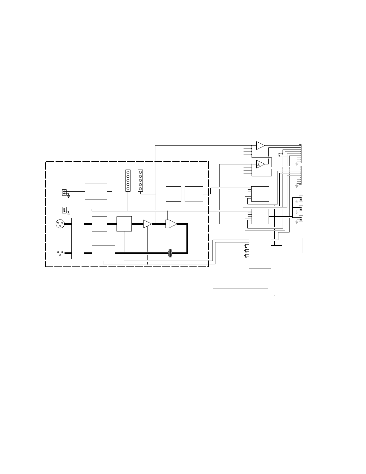
Please refer to the block diagram of the DC1 for the following discussion.
The DC1 has two major subsystems; the analog signal processing and the digital control section.
The audio signal processing includes an ultra-low noise microphone preamp, a high-quality Voltage Controlled
Amplifier (VCA), and an output transformer to prevent ground loops and RF interference. In addition, speech filters
and precision log amplifiers detect audio signals over a wide dynamic range. The headroom detection circuitry
monitors internal signal levels and gives a front panel indication of the amount of signal headroom left. The
attenuation detection circuitry monitors the control voltage to the VCA and gives a front panel indication of the
instantaneous gain reduction in the channel.
The heart of the digital control section consists of a Motorola 68HC705 micro-controller. The micro-controller is
interfaced to the LCD display and front panel buttons, internal analog-to-digital and digital-to-analog converters, and
relay drivers. The automatic mixing algorithm is completely software controlled, which provides a level of
performance difficult to obtain with purely analog systems.
The DC1 is a mic level in, mic level out device. The microphone preamp in each channel may be set (via front
panel control) to 40dB (Input Type: High) or 60dB (Input Type: Low) to accommodate all types of microphones. 48
volt phantom power is also available (via front panel control) on a per channel basis. After the signal is amplified, it
passes through the VCA. From there, the signal is buffered and transformer coupled to a passive attenuation
network, which brings the signal back down to mic level.
Figure 1 - DC1 Block Diagram
2
Page 4

THEORY OF OPERATION (cont’d)
The DC1 audio signal path is designed to eliminate any signal degradation from the DC1 itself. State of the art
microphone preamplifier and voltage controlled amplifier (VCA) ICs are used to process the audio signals. When
the Bypass mode of operation is selected from the front panel, all VCAs are set to unity gain and microphone signal
pass through unaffected. A hardware bypass capability is provided by relays which switch all three pins of the input
and output XLR connectors. If power to the DC1 is lost for any reason, the relays will automatically drop into the
hardware bypass mode, giving fail safe operation. A setup mode exists on the DC1 where the actual input levels of
the microphones are displayed in real time so that differences in microphone sensitivity may be determined.
The automatic mixing algorithm used by the DC1 is called "Adaptive Proportional Gain" (patent pending). The
channel sense level (consisting of a combination of Pre-VCA and Post-VCA signals) from each channel is
continuously compared to the system sense level (the sum of all channel sense levels). Each channel is then
attenuated based on the difference, in dB, between its sense level and the overall sense level. System gain is
automatically shifted toward the microphone(s) with the greatest signal level. As a result, no "threshold" is
necessary to determine when to turn a channel on or off, and the gain allocation is not affected by changes in
ambient noise in the room.
In addition to preamp gain and phantom power, there are a number of other operational parameters that may be
adjusted on the DC1 to optimize the performance for any application. Each channel has two modes of operation,
Auto and Direct. Auto mode sets the channel for automatic operation. Direct turns the channel on under all
circumstances.
Level Match allows the apparent channel signal level to be increased or decreased by up to 30dB, in 1dB
increments. The actual audio signal path gain is unaffected by changes in the Level Match value. The Level Match
function is used to minimize variations in sensitivity (and as a result, access to the system) which might result from
the use of microphones with different sensitivities in the system. In addition, the Level Match function may be used
to give a soft talker access to the system equivalent to louder talkers.
The off attenuation of each channel is also adjustable, from 6dB to 20dB, using the Max Attenuation function. This
allows inactive channels to be attenuated to a greater or lesser degree, depending on the application.
The Auto Gain Skew function provides the capability to minimize the interruption of the active microphone by nonspeech signals such as coughs, paper rattling, etc. Auto Gain Skew dynamically changes the relative proportion of
Pre-VCA to Post-VCA signals which comprise the sense level for a channel. In this way, channels which are active
for a significant amount of time will tend to dominate inactive microphones. Auto Gain Skew also helps eliminate
"bleed-over" of a talker into adjacent closely spaced microphones.
An AutoSet function is included to simplify the process of setting the important parameters of the DC1. The
AutoSet function allows different types of microphones (typically with different sensitivities) to be used with the DC1.
AutoSet automatically calculates the sensitivity differences in the microphones and sets internal parameters for
optimum operation.
3
Page 5
INSTALLATION
"Master"
"Slave"
Master DC1 Slave DC1 Slave DC1
OUT IN OUT IN OUT IN
Installation of the DC1 is quite straightforward. To use one DC1 by itself, simply plug the microphone cables from
up to four microphones into the XLR inputs of the DC1. Connect the XLR outputs of the DC1 to the XLR inputs of
the mixing console.
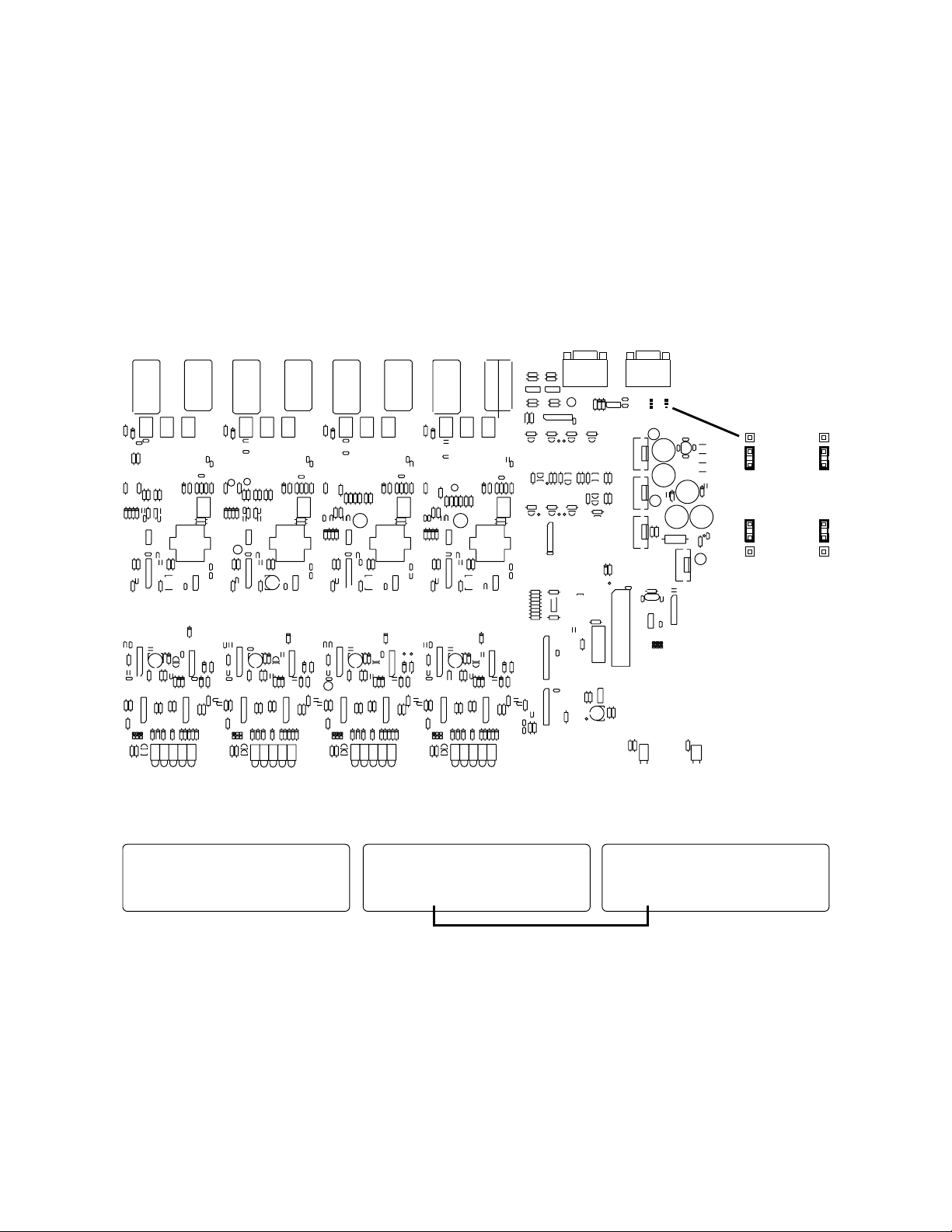
If more than one DC1 is to be used, all but one must be set to the slave mode. Slave mode strapping is
accomplished by removing the top cover of the DC1 and moving the two jumpers in the upper right hand corner of
the DC1 from the forward position (i.e. toward the front panel) to the rear position (i.e. toward the rear panel). In
addition, the DC1’s should be connected using 9 pin subminiature D type cables as shown in Figure 3.
Figure 2 - DC1 Jumper Location and Settings
Figure 3 - Master/Slave Connections
4
Page 6

FRONT PANEL DESCRIPTION
HEADROOM LED METER - Indicates the instantaneous amount of headroom available in the channel. Internal
signals are monitored in each channel, and the Headroom LED meter shows the number of dB before channel
clipping occurs. Note that even with no signal, the "40dB" LED is lit, indicating at least 40dB of headroom.
ATTENUATION LED METER - Indicates the instantaneous amount of attenuation for each channel. Note that the
"20dB" LED is always lit, as the maximum channel attenuation under any circumstance is 20dB.
OPERATE LED - Indicates that the DC1 is in the Operate mode. In the Operate mode, no settings on the DC1
can be adjusted. Note that the Operate LED will flash when the DC1 is in the Bypass mode.
NEW SETTING LED - Indicates the DC1 is in the New Setting mode. In the New Setting mode, adjustments to the
settings on the DC1 can be made and stored as desired.
MODE PUSHBUTTON - Changes the operational mode of the DC1 between Operate, New Setting, and Bypass.
Note the a blinking cursor only appears on the LCD display in the New Setting mode. The blinking cursor is
another cue that changes can be made to DC1 settings. In the Bypass mode, the Operate LED flashes. If the
Mode button is pressed and held while the DC1 is powered up, the DC1 will enter a setup mode whereby the input
signal level of each channel will be displayed in real time. From this screen, access may be gained to the A
function.
UP and DOWN PUSHBUTTONS - Allows the DC1 to be cycled through its function options, as well as enabling the
function values to be changed.
SELECT PUSHBUTTON - Selects the area on the LCD display for which the Up and Down pushbuttons are active.
The blinking cursor will be placed in the selected area. The first line of the display is the name of the selected
function. The second line of the display shows the selected channel, and also the current value of the selected
function.
UTOSET
SAVE PUSHBUTTON - Allows all the current values of DC1 functions to be saved to permanent memory.
POWER LED - Indicates the presence of AC power to the DC1.
POWER SWITCH - Turns the DC1 on or off.
LECTROSONICS
HEADROOM
40 30 20 10 0
CH 1
20 15 10 5 0
ATTENUATION
DIGITAL CONTROL SERIES
CH 2
dB
HEADROOM
40 30 20 10 0
20 15 10 5 0
ATTENUATION
SAVE SELECT DOWN UP MODE
HEADROOM
40 30 20 10 0
CH 3
dB
20 15 10 5 0
ATTENUATION
dB
CH 4
HEADROOM
40 30 20 10 0
20 15 1 0 5
ATTENUATIO N
dB
0
NEW SETTING
OPERATE
Figure 4 - DC1 Front Panel
POWER
5
Page 7

REAR PANEL DESCRIPTION
MICROPHONE INPUT - Accepts a balanced microphone signal. Fully balanced differential input, RF filtered, front
panel selectable 48 volt phantom supply. XLR type connector, Pin 2 is "+", Pin 3 is " ", and Pin 1 is ground.
MICROPHONE OUTPUT - Feeds the input of a standard mixing console. Transformer balanced, XLR type
connector, Pin 2 is "+", Pin 3 is " ", and Pin 1 is ground.
EXPANSION IN/OUT CONNECTORS - provide the capability for more than one DC1 to be used in an installation.
MEMORY PRESETS - Terminal connectors for remote triggering of programmed settings.
CH ON - Terminal connectors for individual channel overrides.
LOGIC - Terminal connectors for signals indicating channel activity. Allows connection to logic controlled devices
for speaker zoning, automated video switching, etc.
LECTROSONICS, INC.
RIO RANCHO, NM - USA
CAUTION
TO REDUCE THE RISK OF FIRE
REPLACE ONLY WITH SAME TY PE
1/4 AMP, 250 VOLT FUSE
100/120V AC 50/60 HZ
30 WATTS
TO REDUCE THE RISK
WARNING
OF FIRE OR ELECTRIC SHOCK, DO
NOT EXPOSE THIS EQUIPMEN T
TO RAIN OR MOISTURE
EXPANSION OUT EXPANSION IN
MEMORY PRE SETS
1 2 3
- + - +
- +
CH 4
CH. ON
LOGIC
- + - +
OUT IN
MADE IN USA
CH. ON
OUT
Figure 5 - DC1 Rear Panel
CH 3
LOGIC
- + - +
CH 3
CH 2
CH. ON LOGIC
- + - +
CH 2
IN
OUT
IN
CH 1
CH. ON
LOGIC
- + - +
CH 1 CH 4
OUT IN
6
Page 8

OPERATING INSTRUCTIONS
Before describing the setup procedure for the system, each function available in the DC1 will be explained.
AUTO SKEW DISPLAY
This function displays the instantaneous mix of Pre and Post VCA signals for each channel. The longer the display
bar for any given channel, the greater is the proportion of Pre-VCA signal to Post-VCA signal. Except in the Auto
Gain Skew "Off" mode, the current active microphone will display the longest bar. Note that this display is the only
DC1 function which is active in both the Operate and New Setting modes.
AUTO GAIN SKEW
The Auto Gain Skew function provides the capability to minimize the interruption of the active microphone by nonspeech signals such as coughs, paper rattling, etc. Auto Gain Skew dynamically changes the relative proportion of
Pre-VCA to Post-VCA channel level signal. In this way, channels which are active for a significant amount of time
will tend to dominate inactive microphones. Auto Gain Skew also helps eliminate "bleed-over" of a talker into
adjacent closely spaced microphones.
The Auto Gain Skew may be set to one of three speeds, Fast, Medium, or Slow in addition to Off. The Fast setting
provides the best operation when the interchange between microphones is lively (e.g. a talk show or panel
discussion), at the expense of some noise rejection. The Slow setting provides the maximum noise rejection, and
is appropriate for situations where there is less interchange between microphones (e.g. a church or lecture). The
Medium setting is a compromise setting. When Auto Gain Skew is Off, all channel signal levels consist of a mix
the Pre-VCA and Post-VCA signals, each attenuated 6dB.
Three alternate settings are useful in situations with high background noise: Fast , Med , and Slow (note the
asterisks). These three settings will release the Auto Gain Skew if the DC1 determines that there is only noise
present on all channels and no valid speech signal.
MAX ATTENUATION
The Max Attenuation adjustment allows the maximum attenuation of each channel to be optimized for both the total
number of microphones in use and the specific acoustic situation. The range of the Max Attenuation adjustment is
6dB to 20dB in 1dB steps.
LEVEL MATCH
The Level Match function allows the apparent channel signal level to be increased or decreased by up to 30dB, in
1dB increments. The actual audio signal path gain is unaffected by changes in the Level Match value. The Level
Match function is used to minimize variations in sensitivity (and as a result, access to the system) which might
result from the use of microphones with different sensitivities in the system. In addition, the Level Match function
may be used to give a soft talker access to the system equivalent to louder talkers.
CHANNEL MODE
There are two operational modes for each channel in the DC1, Direct and Auto. In Direct mode, the channel is on
regardless of activity on that channel or on any other channel. In Auto mode, the channel operates as an
automatic mixer.
PHANTOM POWER
48 volt phantom power is available on a per channel basis. If the microphone requires phantom power, be sure to
turn phantom power on for that channel.
INPUT TYPE
The microphone preamp has two gain settings for high and low level microphone sources. These settings are used
to match the output levels of all types of microphones. The "High" setting is most appropriate for high output
electret microphones. The "Low" setting is better matched to dynamic microphones, which have a lower output
voltage. Note that these are only suggestions, and the actual setting depends on other factors as well, like the
talkers’ distance to the microphone, the talkers average level, etc.
7
Page 9

SETUP PROCEDURE
1) Initialize the memory settings to factory defaults (optional.)
If you do NOT want to lose any previously saved settings, proceed directly to step 2) below.
After the DC1 is installed as outlined in the Installation section above, adjustments may be made to optimize
the performance. The DC1 is shipped from the factory with all parameters preset. These presets provide a
reasonable starting point from which to further optimize the DC1. Note that if the operational parameters are
adjusted and saved, but for some reason it becomes necessary to return the DC1 permanent memory to the
factory presets, this can be accomplished by simultaneously pressing the UP and DOWN buttons and turning
the power on. The LCD display will show the message: " Memory Initialized "
THIS WILL ERASE ALL USER ADJUSTMENTS THAT HAVE BEEN PREVIOUSLY SAVED
2) Set the operating mode to NEW SETTING. Press the MODE button until the yellow New Setting LED is lit.
Adjustments may now be made to all operational parameters.
CONTROLLING THE SETUP SCREENS:
The MODE button selects the operational mode of the DC1 (i.e. Operate, New Setting, or Bypass).
The UP and DOWN buttons scroll through function options, channel numbers, or function values, depending on
the position of the blinking cursor. When the blinking cursor is in the first field of the screen, the UP and
DOWN buttons will advance you to the next/previous screen. If the cursor is in any other field, the UP and
DOWN buttons will change the setting in that field.
The SELECT button moves the blinking cursor between the function options, channel numbers, and function
values of each screen.
The SAVE button stores the current settings of all DC1 functions into the current memory preset.
3) Set phantom power for any microphones that require it. This is accomplished by pressing the UP or
DOWN button until "Phantom Power" appears on the first line of the LCD display. The SELECT button is then
pressed to move the blinking cursor to the "Channel" position on the second line of the LCD display. The UP
or DOWN buttons are again pressed until the desired channel number is reached. The SELECT button is
again pressed to move the blinking cursor to the "Value" position and the UP or DOWN button is pressed to
set the value to ON. When finished, press SELECT to move the cursor back to the Phantom Power field on
the screen. Repeat for all channels.
4) Perform the AutoSet procedure. Refer to page 12, AutoSet Procedure, for step-by-step instructions. Page
11, AutoSet Description, contains a complete description of what AutoSet is and how it works.
5) Select the proper Input Type for the microphone. (Warning: If the AutoSet procedure has already been
performed, the Input Type will already be set. If it is changed here, a 20dB error will be generated because
the final settings generated by the AutoSet procedure depend on the Input Type in effect at the time.)
Choose the "Input Type" function as above and speak in a normal voice into the microphone from the expected
distance of use. Watch the "Headroom" LED display. Set the input type to "HIGH" or "LOW" in order to get
the most action on the "Headroom" display without lighting the red 0dB LED on the display. This gives the
best signal-to-noise performance while leaving adequate margin against clipping. Typically, dynamic
microphones will use LOW and electret microphones will use HIGH. Repeat for all channels.
6) Select the desired Channel Mode for each channel. Press the UP button to advance to the Channel Mode
screen. Auto or Direct may be chosen for each channel as appropriate for the application. Repeat for all
channels.
8
Page 10

7) Set the Level Match for each channel. Press the UP button to advance to the Level Match screen then
press SELECT repeatedly to move the cursor to the Value field. Press the UP and DOWN buttons to set the
Level Match to the desired value.
(Note: If the AutoSet procedure has already been performed, the Level Match will already be set and will not
require readjustment in most cases. Level Match may be "fine tuned" here if necessary.) Level Match inserts
a correction factor to the microprocessor so that the system access of all the channels is the same.
8) Select the maximum attenuation using the "Max Attenuation" function. The choice of attenuation is made
based on the total number of microphones used with the DC1(s). If the total number of microphones is 10 or
less, 10dB of attenuation is adequate. 10 to 32 total microphones requires 15dB of attenuation. 33 or more
total microphones requires 20dB of attenuation. The exact amount of attenuation necessary may be calculated
as 10 * Log
(Number of Microphones) dB. More attenuation than the minimum may be used if desired for the
10
particular application. No ill effects occur if less than the recommended off attenuation is used. Repeat for all
channels.
9) Select the Auto Gain Skew value, or OFF if Auto Gain Skew is not desired.
10) Save the settings. After all desired selections have been made, push the SAVE button to store all chosen
values to non-volatile memory. The following will momentarily be displayed:
All Values Saved .
Note that the DC1 has 3 memory positions, so three complete setups of all function values may be saved in
non-volatile memory. In this way, settings optimized for different applications may be simultaneously saved.
11) Switch the DC1 back to the OPERATE mode. Press the MODE button until the NEW SETTING LED goes
out and the OPERATE LED comes on. Note that on power up, the DC1 will default to the operate mode and
the Auto Skew screen.
9
Page 11

AUTOSET DESCRIPTION
Currently selected Input Type
Memory set
channel Setting
currently selected
Cursor at item
currently selected
for adjustment
Ch:1 InType:HIGH Mem:1
MODE=AutoSet SAVE=Exit
Operator
instructions
The AUTOSET function of the DC1 is included to automatically optimize the performance of the DC1. AUTOSET
allows any mix of microphones to be used with the DC1, while insuring that all microphones will have equal access
to the system. A
period of about 5 seconds. When all microphones have been "listened" to, the DC1 calculates the relative
sensitivities of the microphones and automatically sets the Level Match Adjust parameter for each channel to
enable equal system access for all microphones. Note that it is also possible to change the Level Match Adjust
manually following the A
The AUTOSET screens on the DC1 can be invoked by pressing the MODE switch on the front panel of the DC1
while simultaneously turning on the power with the main power switch. The first screen is the Level dB screen.
This screen shows the input level at each channel in real time. The second screen is the A
screen allows the AUTOSET procedure to be performed.
Level dB Screen
The Level dB screen shows the input level of each channel in real time. Since the level shown for any given
channel includes the effects of the Input Type and Level Match Adjust values that are currently stored in memory,
the user may select any of the three available memories. The Level dB screen may be called both before and
after the A
Level Match Adjust values generated by the AUTOSET procedure should be changed, the information displayed on
the Level dB screen can help the user to determine the amount of change necessary.
A
UTOSET Screen
The AUTOSET screen enables the user to initiate the AUTOSET procedure for each channel. The appropriate Input
Type can be chosen for each channel before A
performed for any of the three available memories in the DC1, and the results will be stored in the chosen memory.
AUTOSET is initiated on a channel by channel basis. After the desired memory is selected, the channel and Input
Type are chosen. With someone speaking in a normal voice at the normal distance from the chosen microphone,
press the MODE button on the front panel of the DC1 to initiate AUTOSET. The MODE LEDs on the front panel will
flash alternately for about 5 seconds while the DC1 determines the relative sensitivity of the microphone. Repeat
this procedure for all channels, and then press the SAVE button. This will calculate and save the Level Match
Adjust values from the A
UTOSET accomplishes this optimization by "listening" to each system microphone in turn for a
UTOSET procedure for any channel.
UTOSET screen. This
UTOSET procedure to assess the results of AUTOSET. In addition, if system circumstances dictate that the
UTOSET is performed. Also, the AUTOSET procedure can be
UTOSET procedure.
Screen Title Channel Input Level Display
Memory set Cursor at item
currently currently selected
selected for adjustment
Figure 17 - Level dB Screen; This screen
appears when the mode switch is held in
during power-up.
Figure 19 - This screen appears momentarily
during the AutoSet Procedure.
Ch:1 InType:HIGH Mem:1
AutoSet in Progress...
Figure 18 - AutoSet Screen; This screen
appears after pressing the MODE button from
the Level dB screen.
10
Page 12

AUTOSET PROCEDURE
STEP BY STEP INSTRUCTIONS
1) If the DC1 is used with a sound system, turn the sound system on and set it for a normal listening
level.
2) Activate the auto set up mode:
Turn the power off;
Hold the MODE switch in and turn power on;
The screen will display the level in dB of all four channels (See Figure 18).
3) Enter the A
Press the MODE switch to enter the A
UTOSET screen:
UTOSET screen.
CH. 1 will be displayed in the upper left corner of
the screen (See Figure 19).
4) Press the SELECT switch to move the cursor to the "InType" position.
5) Set the input type for HIGH or LOW:
Start the noise source at the CH. 1 microphone. If a person will be talking into the microphone instead of
using a pink noise source, have them begin talking or reading into the microphone at the normal working
distance from the microphone. If you are using a noise source such as the Lectrosonics NS1, it should
also be placed at the normal working distance from the microphone.
As the noise is being input to CH. 1, observe the HEADROOM LEDs on CH.1. Press the DOWN or UP
switch to toggle the input type from HIGH to LOW. If the red "0" LED lights with the input type set to
LOW, set the input type back to HIGH. Typically, dynamic microphones will use LOW and electret
microphones will use HIGH.
Note: Once the AUTOSET routine has been run, the Input Type should not be changed. If the Input Type
is changed for any reason, the AUTOSET routine must be run again.
6) Initiate the sampling and automatic level match action:
With the noise or voice signal still being fed into CH.1, press the MODE switch to activate the AUTOSET
routine (See Figure 20). As the signal is sampled and evaluated, the NEW SETTING and OPERATE
LEDs will blink alternately for about 5 seconds. The noise source or talker must continue for the duration
of the sample.
7) Press the SELECT switch to return the cursor to the CH.1 position.
8) Press the UP switch to advance to the next CHANNEL setup screen.
Repeat steps 5 through 8 until all channels are set up.
9) Save settings and exit or review adjustments made:
When all channels have been set up, press the SAVE switch to store all adjustments in memory. The
screen will flash " All Values Saved " briefly and then display a two line prompt asking you to
return to the "Level dB" screen, or to exit the set up procedure.
If desired, the Level dB settings may be reviewed by pressing the MODE switch to return to the "Level dB"
screen. After the settings have been reviewed, press the MODE button again to advance to the AUTOSET
screen where you can push the SAVE button to exit or the MODE button to perform the AUTOSET
procedure again.
CAUTION When in the A
UTOSET screen, pressing the MODE button will initiate the AUTOSET action.
will overwrite any previous AUTOSET settings you may have already done!
11
This
Page 13

DC1 Function Summary and Default Settings
Factory
Feature/Function
Input Type
Channel 1 LOW LOW
Channel 2 LOW LOW
Channel 3 LOW LOW
Channel 4 LOW LOW
Phantom Power
Channel 1 OFF OFF
Channel 2 OFF OFF
Channel 3 OFF OFF
Channel 4 OFF OFF
Channel Mode
Channel 1 DIRECT AUTO AUTO
Channel 2 AUTO AUTO
Channel 3 AUTO AUTO
Channel 4 AUTO AUTO
Level Match
Channel 1 in 1dB increments 0dB 0dB
Channel 2 0dB 0dB
Channel 3 0dB 0dB
Channel 4 0dB 0db
Range
HIGH/LOW
ON/OFF
AUTO
-30dB to +30dB
Default
Mem 1
Factory
Default
Mem 2
User
Mem 3
Max Attenuation
Channel 1 in 1dB increments 20dB 20dB
Channel 2 20dB 20dB
Channel 3 20dB 20dB
Channel 4 20dB 20dB
Auto Gain Skew
(One setting affects
all channels.)
The factory default settings in both MEM 1 and MEM 2 can be customized by the user for each individual installation.
6dB to 20dB
OFF
SLOW, MED, FAST
SLOW , MED , FAST
12
MED MED
Page 14

SPECIFICATIONS
Mic Input:
Impedance: 8.1k Ohms balanced
Type: Electronically balanced and RF filtered
Gain: Unity
EIN, 20-20kHz -127dBu at High Gain, -125dBu at Low Gain
Maximum Input Level -20dBu for "High" Input Type, -40dBu for "Low" Input
Type
Mic Output:
Impedance: Less than 15 Ohms
Type: Transformer balanced
Maximum Output Level: -20dBu at Low Gain, -40dBu at High Gain
Phantom Power: +48 Volts
System THD, 20-20kHz: Less than 0.1%
System IMD, 60Hz/7kHz: Less than 0.1%
Power Consumption 30 Watts at 120VAC
13
Page 15

SERVICE AND REPAIR
If your system malfunctions, you should attempt to correct or isolate the trouble before concluding that the
equipment needs repair. Make sure you have followed the setup procedure and operating instructions. Check out
the inter-connecting cords and then go through the TROUBLE SHOOTING section in the manual
We strongly recommend that you do not try to repair the equipment yourself and do not have the local repair shop
attempt anything other than the simplest repair. If the repair is more complicated than a broken wire or loose
connection, send the unit to the factory for repair and service. Don’t attempt to adjust any controls inside the units.
Once set at the factory, the various controls and trimmers do not drift with age or vibration and never require
readjustment. There are no adjustments inside that will make a malfunctioning unit start working.
LECTROSONICS service department is equipped and staffed to quickly repair your equipment. In-warranty repairs
are made at no charge in accordance with the terms of the warranty. Out of warranty repairs are charged at a
modest flat rate plus parts and shipping. Since it takes almost as much time and effort to determine what is wrong
as it does to make the repair, there is a charge for an exact quotation. We will be happy to quote approximate
charges by phone for out of warranty repairs.
RETURNING UNITS FOR REPAIR
You will save yourself time and trouble if you will follow the steps below:
A. DO NOT return equipment to the factory for repair without first contacting us by letter or by phone. We need to
know the nature of the problem, the model number and the serial number of the equipment. We also need a
phone number where you can be reached 8 am to 4 pm (Mountain Standard Time).
B. After receiving your request, we will issue you a return authorization number (R.A.). This number will help
speed your repair through our receiving and repair departments. The return authorization number must be
clearly shown on the outside of the shipping container.
C. Pack the equipment carefully and ship to us, shipping costs prepaid. If necessary, we can provide you with the
proper packing materials. UPS is usually the best way to ship the units. Heavy units should be "double-boxed"
for safe transport.
D. We also strongly recommend that you insure the equipment, since we cannot be responsible for loss of or
damage to equipment that you ship. Of course, we insure the equipment when we ship it back to you.
Mailing address: Shipping address: Telephones:
Lectrosonics, Inc. Lectrosonics, Inc. (505) 892-4501
PO Box 15900 581 Laser Rd. (800) 821-1121
Rio Rancho, NM 87174 Rio Rancho, NM 87124 FAX: (505) 892-6243
USA USA
World Wide Web: http://www.lectrosonics.com email: sales@lectrosonics.com
14
Page 16

LIMITED ONE YEAR WARRANTY
The equipment is warranted for one year from date of purchase against defects
in materials or workmanship provided it was purchased from an authorized
dealer. This warranty does not cover equipment which has been abused or
damaged by careless handling or shipping. This warranty does not apply to
used or demonstrator equipment.
Should any defect develop, we will, at our option, repair or replace any
defective parts without charge for either parts or labor. If we cannot correct the
defect in your equipment, we will replace it at no charge with a similar new item.
We will pay for the cost of returning your merchandise to you.
This warranty applies only to items returned to us, shipping costs prepaid, within
one year from the date of purchase.
This warranty gives you specific legal rights. You may have additional legal
rights which vary from state to state.
LECTROSONICS, INC.
581 LASER ROAD
RIO RANCHO, NM 87124 USA July 6, 1999
 Loading...