

Page 1
Quick
Start
Guide
Digital Belt Pack Transmitter
Fill in for your records:
Serial Number:
Purchase Date:
Digital Hybrid Wireless® US Patent 7,225,135
This guide is intended to assist with
initial setup and operation of your
Lectrosonics product.
For a detailed user manual, download the most current
version at:
www.lectrosonics.com
31 May 2019
Page 2
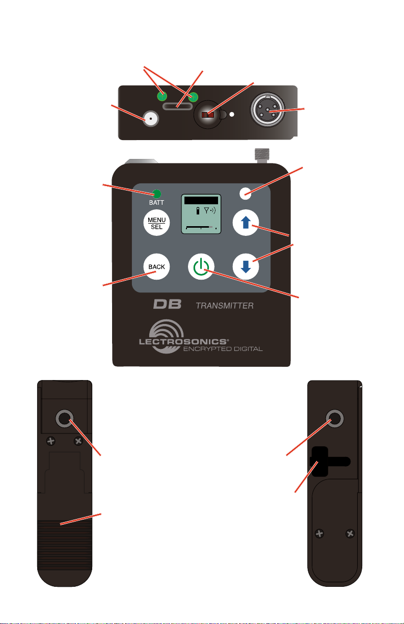
DBu Features and Functions
Modulation
Indicators*
IR Port
Function Switch
Programmable
Antenna
Port
Battery
status LED
Return to
previous screen
-20
AUDIO
IR PORT
DBu
470.100
-40
u
-10
-20
PWR/FUNC
+0
Audio
Input
Jack
Key verification
LED
Menu navigation
buttons
Power button
Belt clip
mounting hole
Battery
compartment
door
LECTROSONICS, INC.2
Belt clip
mounting hole
USB Port
Page 3
Programmable Switch
The transmitter can also be configured as a “one button” device by locking the
ability to make changes with the keypad, and configuring the top panel switch
as either power on/off or a mute function.
Modulation Indicator LEDs
When the transmitter is set to MUTE, the -10 Modulation Indicators LED will
glow solid red. Otherwise, the -10 Modulation Indicators LED will glow solid
green when transmitter is on.
Belt Clips
The wire belt clip may be removed by pulling the ends out of the holes in the
sides of the case. Be sure to have a firm grip to avoid scratching the surface
of the housing.
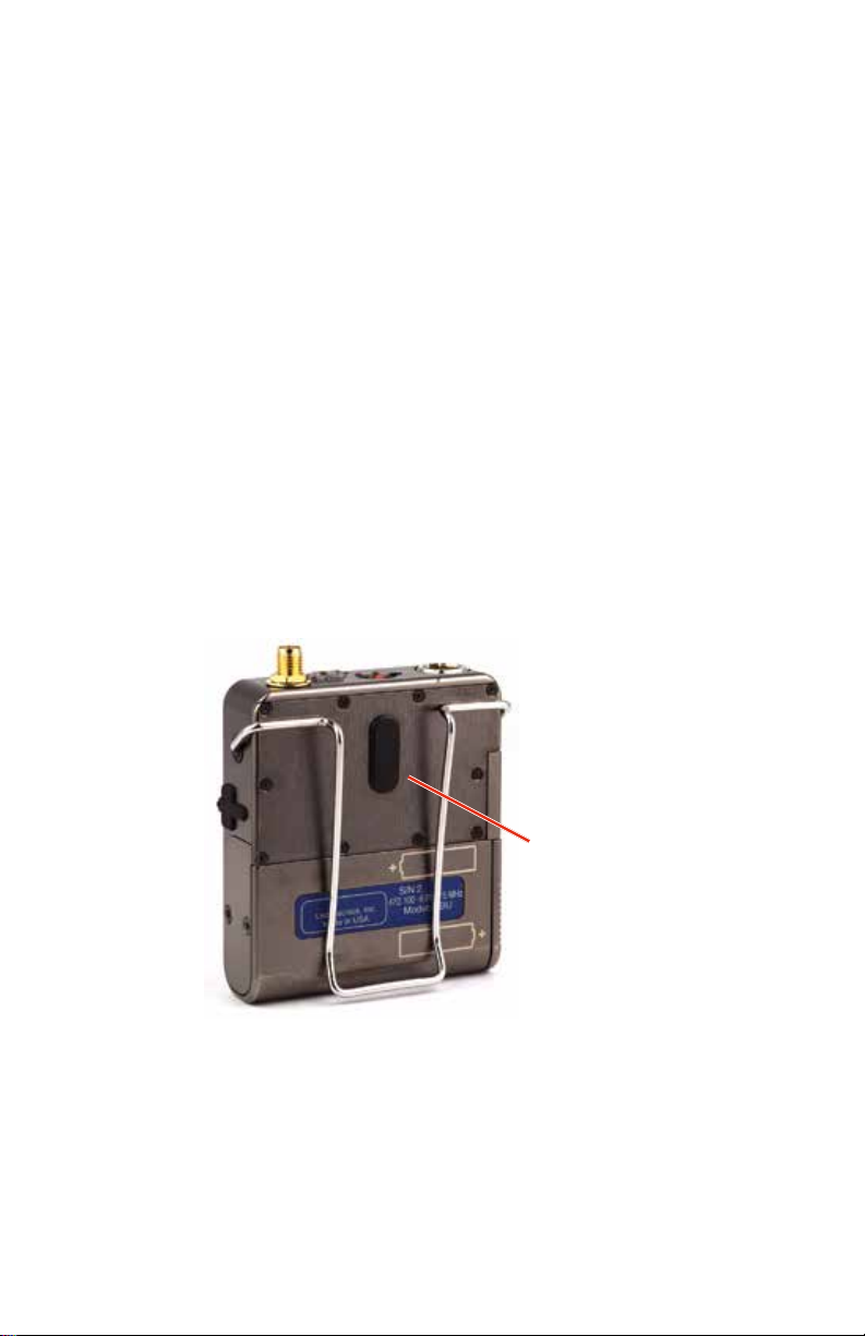
An optional spring-loaded, hinged belt clip (model number BCSLEBN) is also
available. This clip is attached by removing the plastic hole cap on the back of
the housing and mounting the clip with the supplied screw.
IR (infrared) Port
The IR port is available on the top of the transmitter for quick setup using a
receiver with this function available. IR Sync will transfer the settings for frequency from the receiver to the transmitter.
Remove hole cap to
attach spring loaded
belt clip
www.lectrosonics.com 3
Page 4
Battery Installation
The transmitter is powered by two AA batteries. We recommend using alkaline, lithium, or rechargeable batteries for longest life.
The battery status circuitry compensates for the difference in voltage drop
between alkaline and lithium batteries across their usable life, so it’s important
to select the correct battery type in the menu.
Because rechargeable batteries run down quite abruptly, using the Power
LED to verify battery status will not be reliable. However, it is possible to track
battery status using the battery timer function available in the receiver.
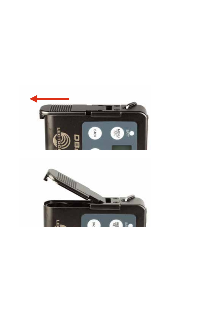
Push outward on the battery compartment door and lift it to open.
Slide door out to release catch
Lift door to open
Insert the batteries according to the markings on the back of the housing.
If the batteries are inserted incorrectly, the door will close but the unit will not
operate.
LECTROSONICS, INC.4
Page 5
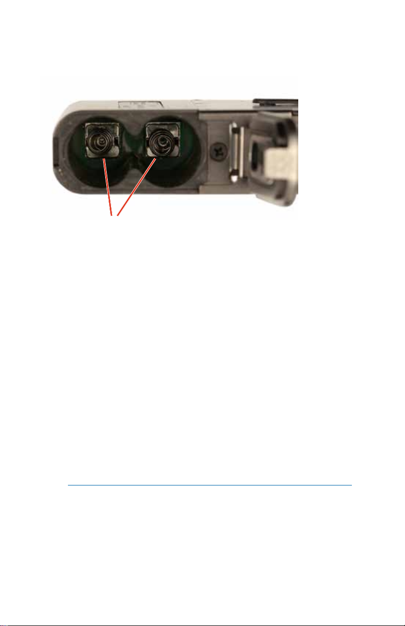
The battery contacts can be cleaned with alcohol and a cotton swab, or a
clean pencil eraser. Be sure not to leave any remnants of the cotton swab or
eraser crumbs inside the compartment.
Contact springs
Battery Status LED Indicator
Alkaline, lithium or rechargeable batteries can be used to power the transmitter. The type of batteries in use are selectable in a menu on the LCD.
When alkaline or lithium batteries are being used, the LED labeled BATT on
the keypad glows green when the batteries are good. The color changes to red
when the they are nearing the end of life. When the LED begins to blink red,
there will be only a few minutes remaining.
The Power/Function LED on the top panel will mirror the keypad LED unless
the programmable switch is set to Mute, and the switch is turned on.
The exact point at which the LEDs turn red will vary with battery brand and
condition, temperature and power consumption. The LEDs are intended to
simply catch your attention, not to be an exact indicator of remaining time.
A weak battery will sometimes cause the Power LED to glow green immediately after the transmitter is turned on, but it will soon discharge to the point
where it will turn red or the unit will turn off completely.
Rechargeable batteries give little or no warning when they are depleted. If
you wish to use these batteries in the transmitter, the most accurate way to
determine runtime status is by testing the time provided by a particular battery brand and type, then using the BatTime function to determine remaining
runtime.
NOTE: Refer to the Main Menu and Setup Section for BatTime details.
www.lectrosonics.com 5
Page 6

Operating Instructions
Powering On in Operating Mode
Press and hold the Power Button until a status bar on the LCD is completed.
Hold
DBu
DBu
for
Rf On
V1.13
/1.05
When you release the button, the unit will be operational with the RF output
turned on and the Main Window displayed.
470.100
-40
-20
+0
Powering On in Standby Mode
A brief press of the Power Button , and releasing it before status bar has
completed, will turn the unit on with the RF output turned off. In this Standby
Mode the menus can be browsed to make settings and adjustments without
the risk of interfering with other wireless systems nearby.
Hold
for
Rf On
After settings and adjustments are made, press the power button again to turn
the unit off.
Release Power
Button before
the status bar
has completed
to enter standby
mode
RF indicator blinks
DBu
470.100
-40
-20
+0
Powering Off
Powering
O . . .
From any screen, power can be turned off by selecting
Pwr Off in the power menu, holding the Power Button
in and waiting for the status bar to complete, or with the
programmable switch (if it is configured for this function).
If the power button is released, or the top panel switch is
turned back on again before the status bar is completed,
the unit will remain turned on and the LCD will return to
the same screen or menu that was displayed previously.
NOTE: If the programmable switch is in the OFF position, power can
still be turned on with the power button. If the programmable switch is
then turned on, a brief message will appear on the LCD.
LECTROSONICS, INC.6
Page 7

Power Menu Options
Entering the Power Menu
With the unit turned on, press the power button once briefly from any menu
or screen and a menu will appear with several options. Use the
row buttons to highlight menu items. Then press MENU/SEL to execute the
item or enter a setup screen. The following options are available:
• Resume - returns to the previous mode and screen
• Pwr Off - turns the unit off irrevocably
• Rf On? - enters a screen to enable the operating or standby modes
• AutoOn? - allows the unit to automatically turn back on after a power
failure or when fresh batteries are installed (works in the operating mode
only)
• Backlit - adjusts the duration of the LCD back light to 5 seconds or 30
seconds, or to remain on
• About - displays model number and firmware
version
and ar-
www.lectrosonics.com 7
Page 8
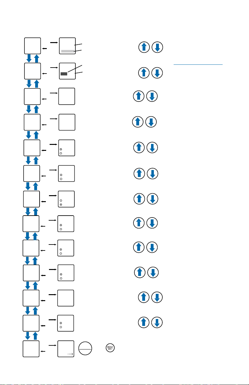
LCD Menu Map
Use arrow buttons
Gain
Gain
SEL
BACK
to select value
22
Level meter at bottom of screen
Freq.
ProgSw
Rolloff
Phase
BatType
TxPower
Remote
Locked?
SEL
SEL
SEL
SEL
SEL
SEL
SEL
SEL
BACK
BACK
BACK
BACK
BACK
BACK
BACK
BACK
Freq.
470.675
ProgSW
Rolloff
50 Hz
Phase
Normal
Invert
BatType
Alk.
Lith.
TxPower
25 mW
50 mW
Remote
Enable
Ignore
Locked?
Yes
No
Press MENU/SEL to highlight MHz or kHz
Select value with arrow buttons
Select option with arrow buttons
Power
(None, TalkBk, Powe r, Mute)
Select value with arrow buttons
(35, 50, 70, 100, 120, 150 Hz)
Select option with arrow buttons
Select option with arrow buttons
Select option with arrow buttons
Select option with arrow buttons
Select option with arrow buttons
NOTE: The settings
will be stored when
the BACK button
is pressed.
Default
KeyType
WipeKey
SendKey
SEL
SEL
SEL
SEL
BACK
BACK
BACK
BACK
Default
Settings
No
Yes
KeyType
Universal
WipeKey?
No
Yes
SendKey
Share
LECTROSONICS, INC.8
Select option with arrow buttons
Select option with arrow buttons
(Universal, Shared, Standard or Volatile)
Select option with arrow buttons
(Only available when KeyType is set to
Standard, Shared or Volatile)
MENU
Press to send key
SEL
(Only available when KeyType is set to Shared)
Page 9

Main Menu and Setup Screen Details
Entering the Main Menu
The LCD and keypad interface makes it easy to browse the menus and make
the selections for the setup you need. When the unit is powered up in either
the operating or the standby mode, press MENU/SEL on the keypad to enter
a menu structure on the LCD. Use the
menu item. Then press the MENU/SEL button to enter the setup screen.
Gain
Gain
Freq.
ProgSw
Rolloff
-40
Main Window Indicators
The Main Window displays programmable switch function, Standby or Operating mode, operating frequency, audio level and battery status.
Programmable
Switch Function
and arrow buttons to select the
The prompt in the upper
right corner may display
25
-20
DBu
MUTE
one or both arrows,
depending upon what
adjustment can be made.
If the changes are locked,
a small padlock symbol
0
will appear.
Operating
mode
Frequency (MHz)
-40
-20
Audio level
Mute function
enabled but
not active
DBu
MUTE
470.100
-40
-20
+0
470.100
When the switch is turned
on, the mute icon appearance will change and the
word MUTE will blink at the
bottom of the display. The
-10 LED on the top panel
will also glow solid red.
www.lectrosonics.com 9
DBu
MUTE
470.100
<–MUTE–>
Battery status
+0
If the programmable
switch function is set
for Mute, the Main
Window will indicate
that the function is
enabled.
Main Window will blink
the word MUTE when
the audio is muted
Page 10

Connecting the Signal Source
Microphones, line level audio sources and instruments can be used with
the transmitter. Refer to the section entitled Input Jack Wiring for Different
Sources for details on the correct wiring for line level sources and microphones to take full advantage of the Servo Bias circuitry.
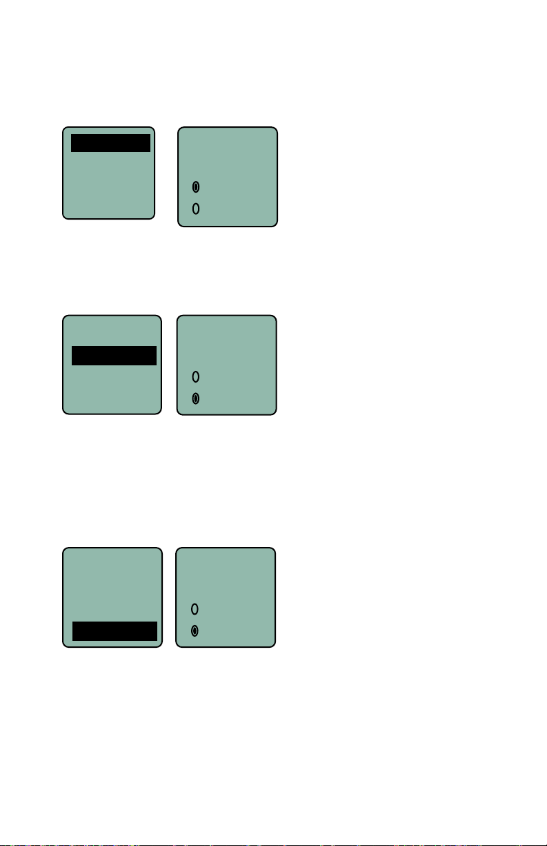
Adjusting the Input Gain
The two bicolor Modulation LEDs on the top panel provide a visual indication
of the audio signal level entering the transmitter. The LEDs will glow either red
or green to indicate modulation levels as shown in the following table.
Signal Level -20 LED -10 LED
Less than -20 dB
-20 dB to -10 dB
-10 dB to +0 dB
+0 dB to +10 dB
Greater than +10 dB
NOTE: Full modulation is achieved at 0 dB, when the “-20” LED first
turns red. The limiter can cleanly handle peaks up to 30 dB above this
point.
It is best to go through the following procedure with the transmitter in the
standby mode so that no audio will enter the sound system or recorder during
adjustment.
1) With fresh batteries in the transmitter, power the unit on in the standby
mode (see previous section Powering On in Standby Mode).
2) Navigate to the Gain setup screen.
Off Off
Green Off
Green Green
Red Green
Red Red
Gain
Freq.
Gain
25
ProgSw
Rolloff
3) Prepare the signal source. Position a microphone the way it will be used
in actual operation and have the user speak or sing at the loudest level
that occur during use, or set the output level of the instrument or audio
device to the maximum level that will be used.
4) Use the and arrow buttons to adjust the gain until the –10 dB glows
green and the –20 dB LED starts to flicker red during the loudest peaks
in the audio.
5) Once the audio gain has been set, the signal can be sent through the
sound system for overall level adjustments, monitor settings, etc.
6) If the audio output level of the receiver is too high or low, use only the
controls on the receiver to make adjustments. Always leave the transmitter gain adjustment set according to these instructions, and do not
change it to adjust the audio output level of the receiver.
LECTROSONICS, INC.10
-40
-20
0
Page 11

Selecting Frequency
The setup screen for frequency selection offers two ways to browse the available frequencies.
Frequency groups are also able to be received via IR (Inrared) port sync.
The group options are set by the receiver, and will show at the bottom of the
screen as No Grp, Grp x, Grp w, Grp v, or Grp u.
Use the MENU/SEL button to toggle between options and UP and DOWN
arrows to adjust.
Gain
Freq
Freq
Freq.
ProgSw
Rolloff
628.200
Grp x
628.200
Grp x
Selecting Programmable Switch Functions
The programmable switch on the top panel can be configured using the menu
to provide several functions:
• (none) - disables the switch
• Mute - mutes the audio when switched on; LCD will blink a message and
-10 LED will glow solid red.
• Power - turns the power on and off
• TalkBk - switches the audio output on the receiver to a different channel
for communication with the production crew. Requires a receiver with this
function enabled.
Gain
Freq.
ProgSw
Rolloff
NOTE: The programmable switch will continue to operate whether or
not keypad changes are locked.
ProgSw
Power
Use the and
arrow buttons to
select the desired
function or disable
the switch
Selecting the Low Frequency Roll-off
The low frequency audio roll-off is adjustable to
Rolloff
70 Hz
www.lectrosonics.com 11
optimize performance for ambient noise conditions
or personal preference.
Low frequency audio content may be desirable or
distracting, so the point at which the roll-off takes
place can be set to 20, 35, 50, 70, 100, 120
or 150 Hz.
Page 12
Selecting Audio Polarity (Phase)
Audio polarity can be inverted at the transmitter so the audio can be mixed
with other microphones without comb filtering. The polarity can also be inverted at the receiver outputs.
Phase
Phase
BatType
TxPower
Remote
Normal
Invert
Selecting Battery Type
The voltage drop over the life of different batteries varies by type and brand.
Be sure to set the correct battery type for accurate indications and warnings.
The menu offers alkaline or lithium types.
Phase
BatType
BatType
TxPower
Remote
If you are using rechargeable batteries, it is better to use the timer function
on the receiver to monitor the battery life rather than the indicators on the
transmitter. Rechargeable batteries maintain a fairly constant voltage across
the operating time on each charge and stop working abruptly, so you will have
little or no warning as they reach the end of operation.
Alk.
Lith.
Setting Transmitter Output Power
The output power can be set to 25 mW or 50 mW.
Rolloff
TxPower
Phase
BatType
TxPower
25 mW
50 mW
Remote
Remote control “dweedle” tones from a smart phone can be used to control
the transmitter.
LECTROSONICS, INC.12
Page 13

Locking/Unlocking Changes to Settings
Changes to the settings can be locked to prevent inadvertent changes being
made.
BatType
Locked?
TxPower
Remote
Locked?
A small padlock symbol will appear on adjustment
screens when changes have been locked.
When changes are locked, several controls and actions can still be used:
• Settings can still be unlocked
• Menus can still be browsed
• Programmable switch still works (Mute and On/Off)
• Power can still be turned off by using the power menu or removing the
batteries.
Ye s
No
Gain
-40
-20
25
0
Restoring Default Settings
This is used to restore the factory settings.
Remote
Locked?
Default
KeyType
Default
settings
No
Ye s
www.lectrosonics.com 13
Page 14

KeyType
The DBu receives an encryption via the IR port from a key generating receiver. Begin by selecting a key type in the receiver and generating a new key
(key type is labeled KEY POLICY in the DSQD receiver). Set
the matching KEY TYPE in the DBu and transfer the key from the receiver
(SYNC KEY) to the DBu via the IR ports. A confirmation message will display
on the receiver display if the transfer is successful. The
transmitted audio will then be encrypted and can only be listened to if the
receiver has the matching encryption key.
The DBu has three options for encryption keys:
Remote
KeyType
Locked?
Default
Standard
KeyType
• Shared: There are an unlimited number of shared keys available. Once
generated by a receiver and transferred to the DBu, the encryption key
is available to be shared (synced) by the DBu with other transmitters/receivers via the IR port. When a transmitter is set to this key type, a menu
item named SEND KEY is available to transfer the key to another device.
• Universal: This is the most convenient encryption option available. All
encryption-capable Lectrosonics transmitters and receivers contain the
Universal Key. The key does not have to be generated by a receiver. Simply set the DBu and a Lecrosonics receiver to Universal, and the encryption is in place. This allows for convenient encryption amongst multiple
transmitters and receivers, but not as secure as creating a unique key.
• Standard: This is the highest
level of security. The encryption
keys are unique to the receiver
and there are only 256 keys
available to be transferred to a
transmitter. The receiver tracks
the number of keys generated
and the number of times each
key is transferred.
WipeKey
Default
KeyType
WipeKey
SendKey
SendKey
Default
KeyType
WipeKey
SendKey
WipeKey?
No
This menu item is only available if
Key Type is set to Standard or
Shared. Select Yes to wipe the
current key and enable the DBu to
receive a new key.
Ye s
This menu item is only
SendKey
Share:
LECTROSONICS, INC.14
available if Key Type is set to
Shared. Press Menu/Sel to
sync the Encryption key to
another transmitter or receiver via the IR port.
Page 15

Whip Antennas
Because the transmitter tunes across such a broad frequency range, it is best
to use the appropriate antenna for maximum operation. Three antennas are
included with the transmitter, and are shipped from the factory pre-cut and
fully assembled. Each antenna covers three blocks. Use the chart below to
determine which antenna best fits your needs.
Frequency Cap
Block Range MHz Color Antenna
470 470.100 - 495.600 Black AMM19
19 486.400 - 511.900 Black AMM19
20 512.000 - 537.500 Black AMM19
21 537.600 - 563.100 Red AMM22
22 563.200 - 588.700 Red AMM22
23 588.800 - 614.300 Red AMM22
Encryption Key and Settings Transfer
A cable between the receiver and the micro USB port on the side of the transmitter is used to transfer the encryption key from the receiver to the transmitter. This connection can also be used to send the transmitter settings stored in
the receiver to the transmitter.
The interface cable, P/N DRKEYCABLE, is used to make this connection.
NOTE: Reference the DSW System Instruction Manual for instructions
on Encryption Key settings and software.
www.lectrosonics.com 15
Page 16

 Loading...