

Page 1

CR185
COMPACT RECEIVER
OPERATING INSTRUCTIONS
and trouble-shooting guide
LECTROSONICS, INC.
Rio Rancho, NM
Page 2

INTRODUCTION
Thank you for selecting the Lectrosonics Professional Series wireless microphone system. This system
represents well over 10 years of manufacturing experience in wireless microphones, and almost 70
years of design experience.
The CR185 receiver design is the result of surveying the needs of professional video producers, ENG
cameramen and many others in the broadcast and pro video industry. Hundreds of conversations with
dealers and end-users developed the final parameters for the design.
The CR185 receiver is a fixed frequency design that eliminates the need to "tune" or adjust the receiver
every time it is used. This is the preferred design for a number of reasons, among them simplicity of
operation, no adjustments in "high pressure" situations, and interference rejection by design rather than
by trying to "tune" it out.
The CR185 miniature receiver was designed by professionals for outstanding performance and
flexibility, while preserving ease of operation. It is compatible with all Lectrosonics high band
transmitters. The CR185 receiver represents one of the best values in wireless receivers, regardless of
price.
TABLE OF CONTENTS
INTRODUCTION .......................................... 1
GENERAL TECHNICAL DESCRIPTION .......................... 2
CONTROLS AND FUNCTIONS
FRONT PANEL ..................................... 3
REAR PANEL ...................................... 5
BATTERY REPLACEMENT ................................... 5
ANTENNA USE AND PLACEMENT ............................. 6
OPERATING INSTRUCTIONS ................................. 7
INDICATOR QUICK REFERENCE .............................. 7
TROUBLESHOOTING ....................................... 8
CR185 REPLACEMENT PARTS AND ACCESSORIES ............... 8
SERVICE AND REPAIR ..................................... 9
RETURNING UNITS FOR REPAIR ............................. 9
SPECIFICATIONS AND FEATURES
WARRANTY ........................................ Back cover
............................ 10
1
Page 3
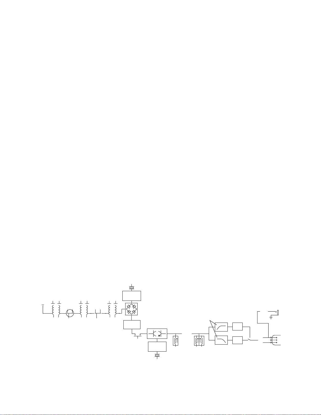
GENERAL TECHNICAL DESCRIPTION
JFET
RF AMP
ANT
LC FILTERS
2:1
SQUELCH
NOISE
AUDIO
0.5uV
2 SECTION
HELICAL
RESONATOR
2 SECTION
HELICAL
RESONATOR
JFET
RF AMP
2 SECTION
HELICAL
RESONATOR
1ST
LOCAL
OSCILLATOR
DBL BAL
DIODE
MIXER
1ST
IF AMP
6 POLE
HIGH FREQ
CRYSTAL
FILTER
DBL BAL
ACTIVE MIXER
2ND
LOCAL
OSCILLATOR
2ND
IF AMP
ACTIVE FILTERS SEPARATE
NOISE AND AUDIO
DBL TUNED
DISCRIMINATOR
COMPLEMENTARY
EXPANDER
BALANCED
OUTPUT STAGE
HEADPHONE
AMP
The CR185 receiver is comprised of six major functional subsystems: the RF front-end amplifier, the
double balanced mixer/local oscillator, the first IF filter, the second IF filter and audio demodulator, the
compandor, and the balanced microphone level output circuit.
The RF front-end amplifier consists of three cascaded pairs of helical resonators for high selectivity.
Between the first and second helical resonators, and the second and third helical resonators are low
noise grounded gate JFET amplifiers. These amplifiers are designed to provide only enough gain to
make up for the loss through the helical resonators. This combination of low front-end gain, coupled
with the extremely high selectivity of the cascaded helical resonators results in no overloading, even on
extremely strong signals. Rejection of out of band signals is maximized, and intermodulation products
are suppressed.
The mixer stage consists of a high level double balanced diode mixer. The oscillator is biased from a
/regulated supply, yielding stable performance over the entire life of the battery. The local oscillator
crystal operates at approximately 16mHz, and can be adjusted above and below the nominal frequency
in order to place the 21.4mHz IF in the center of the crystal filter’s narrow passband. The high
selectivity of the crystal filter stage further minimizes the possibility of interference from signals on
adjacent frequencies.
The second IF filter and the audio demodulator, as well as the squelch and RF output LED drive are
provided by one monolithic integrated circuit. The second IF filter is centered on 1mHz, and drives a
double tuned quadrature type FM demodulator. The squelch circuit is a supersonic noise detector type
and is factory set for a -20dB SINAD level (about .5uV). The squelch level is regulated and
temperature compensated to maintain a consistent squelch level under all conditions.
The compandor is driven by a multiple pole active low-pass filter. The filter ensures that supersonic
noise will not cause the compandor to increase gain incorrectly. This filter also drives the -20dB
modulation LED. The compandor senses the signal level, and dynamically increases the gain for loud
signals or decreases the gain for soft signals. In this way, the original dynamic range of the transmitted
signal is restored, while preserving a high signal-to-noise ratio. The expansion ratio is 2:1, which
produces a 2dB change in output signal level for a 1dB change in input level. In addition, the
compandor has a de-emphasis network that is complementary to the pre-emphasis network in the
transmitter.
The balanced microphone level output circuit generates a truly balanced signal at the XLR output
connector. The volume control is a balanced attenuator, and gives a gain range from -20dBV (at full
modulation) in the fully clockwise position to -50dBV in the fully counter-clockwise position. In addition,
the headphone circuit is driven from the microphone circuit. This means that the headphone output
level is dependent not only on the headphone volume control, but also the microphone level control.
Figure 1 - CR185 Receiver Block Diagram
2
Page 4

CONTROLS AND FUNCTIONS
RECEIVER FRONT PANEL
MODULATION LEDs
Indicate the modulation (audio level) of the incoming signal, and can be used for proper adjustment of
the transmitter’s "MIC LEVEL" or "GAIN". The -20 LED glows when the transmitter modulation is at a
high enough level to produce a good audio signal-to-noise ratio. It will normally flicker, or stay lit as
you speak into the microphone. The 0dB lamp indicates a "peak," showing that the transmitter
modulation is at maximum. Constant lighting may indicate that the audio gain in the transmitter may be
set too high. It is normal and desirable that you see an occasional flicker of the 0dB lamp in typical
use.
OUTPUT CONTROL
Attenuates the audio output level of the receiver to match the input requirements of the equipment with
which it is used. The XLR output jack on the rear panel provides an audio output at microphone level
for low impedance, balanced inputs. At the extreme counter-clockwise position of the control knob, the
output level of this XLR jack will be 50dB at full modulation. In the fully clockwise position, the output
level will be -20dB at full modulation. Intermediate settings are sometimes necessary due to the
variations in different input compressors and ALC (automatic level control) circuits on various VCR’s
and audio inputs. The markings around the control knob are provided simply as "memory markers;"
they are not calibrated with reference to a specific output level.
EXT/OFF/INT SWITCH
Turns the receiver power off and on and selects either internal 9 Volt battery power, or external 12 Volt
DC power (of either polarity).
POWER LED
Glows when the power switch is in the proper position and the battery is good, or when external 12 Volt
DC power is properly supplied. If this LED is very dim or does not light up when the switch is turned
on, replace the battery or check the connections from the external power source. The LED glows
brightly to indicate a good battery and dims as the battery voltage decreases.
The POWER LED is connected to a precision battery test circuit that continuously monitors battery
voltage. The LED is at full brightness with a new 9 volt alkaline battery. As the battery voltage drops
during use, the LED brightness will also decrease. After 4 to 5 hours, the battery voltage will be about
7 volts. The LED will be completely extinguished.
IMPORTANT!
When the battery voltage drops below 6 Volts, the power LED will remain off, but the other 3
LEDs will light up and a loud rush of audio noise will be heard as the squelch opens. This
condition is normal, and is easily remedied by replacing the battery.
3
Page 5

CONTROLS AND FUNCTIONS
Since the internal circuits are all tightly regulated the receiver will continue to operate to a battery
voltage of 6.5 volts. From 6.5 volts to 6 volts, the receiver will still operate, but with degraded
performance. Below 6 volts, the regulated and temperature compensated squelch circuit will cease to
be regulated. The result is that the squelch circuit will remain "open". This will allow considerable
noise to pass through the audio circuits if the associated transmitter is off, or if other circuits of the
CR185 stop operating because of the low voltage condition. In addition, three out of the four LEDs on
the front panel will light (the exception being the POWER LED). Please note that a weak battery will
sometimes light the POWER LED immediately after turn on, but soon will discharge to the point where
the LED will extinguish. Regular installation of fresh batteries will insure optimum operation.
RF LED
Lights when the transmitter is turned on and the receiver has a good signal. When the carrier signal
from the transmitter is too weak to produce a clean audio signal, the lamp will go out.
MINI PHONE JACK
Provides a monitor, separate from the rear panel XLR audio output. The output level from this jack is
controlled by both the OUTPUT control and the recessed trim-pot on the side panel. Generally, the
OUTPUT control would be set to provide the proper output level at the rear panel XLR jack, and then
the side panel trim-pot adjusted to match the required level for your earphone.
The output at this mini connector is designed for a medium impedance earphone. An earphone with an
impedance between 30 and 300 Ohms will usually provide adequate volume. The sound from a low
impedance ear phone (ie. 8 Ohms) will not be very loud and may be distorted at higher listening levels.
ANT TERMINAL
Connects to any 50 ohm antenna with a BNC type connector (a flexible "rubber duckie" antenna is
supplied). The A-185 Coax remote type antenna may also be used.
Adjust headset volume with
the trimpot on the side.
LECTROSONICS
CR185
OFF
- -
50
MODULATI ON
-
20
0dB
Figure 2 - CR185 Front Panel
dBV
OUTPUT
20
EXT
POWER
INT
BATT
RF
4
Page 6

RECEIVER REAR PANEL
12 VDC INPUT
Connects to the supplied CH-12 AC adapter for powering the receiver from a 110/120V AC source. The
receiver may also be powered from external 12 volt DC sources using the correct plug (Switchcraft
S-760 power plug). A diode bridge is used in the external power input, so that the CR185 will operate
properly from either polarity.
AUDIO OUTPUT
Supplies a balanced, low impedance output at microphone level. The audio signal is output on pins 2
and 3, while pin 1 is ground. The output level of this jack is controlled by the OUTPUT control on the
front panel of the receiver. The connector is a standard XLR type.
BATTERY REPLACEMENT
The CR185 is powered by a standard alkaline 9 volt battery. It is important that you use ONLY an
ALKALINE battery for longest life. Standard zinc-carbon batteries marked "heavy duty" or "long-lasting"
are not adequate. They will provide only about one hour of operation. Similarly, nicad rechargeable
batteries give less than 2 hours of operation, and will also run down quite abruptly. Alkaline batteries
provide about 5 hours of operation.
To open the battery compartment, press outward on the cover door in the direction of the arrow as
shown in the drawing. Only slight, sliding pressure is needed to open and close the battery door.
TO OPEN
AUDIO OUTPUT
Figure 3 - CR185 Battery Replacement
Swing the door open and take note of the polarity marked inside showing the location of the positive (+)
and negative (-) terminals. Insert the battery and close the cover by pressing in and across, reversing
the opening procedure outlined above. Note that the battery door will NOT close if the battery is
inserted incorrectly, since the terminals will hit a protective polarity barrier. Do not force the battery in.
12 VOLT DC INPUT
5
Page 7

ANTENNA USE AND PLACEMENT
EXAMPLE MOUNTING LOCATIONS
FOR SINGLE OR MULTIPLE
CR185 RECEIVER(S)
Connect the antenna to the front panel jack. Position the antenna so that it is not within 3 or 4 feet of
large metal surfaces. If this is not possible, try to position the antenna so that it is as far away from the
metal surface as is practical. It is also good to position the receiver so that there is a direct "line of
sight" between the transmitter and the receiver antenna. In situations where the operating range is less
than about 50 feet, the antenna positioning is much less critical.
A wireless transmitter sends a radio signal out in all directions. This signal will often bounce off nearby
walls, ceilings, etc. and a strong reflection can arrive at the receiver antenna along with the direct
signal. If the direct and reflected signals are out of phase with each other a cancellation may occur.
The result would be a "drop out." A drop out sounds like either audible noise (hiss), or in severe cases,
may result in a complete loss of the carrier and the sound. Moving the transmitter even a few inches
may eliminate it. A dropout situation may be either better or worse as the crowd fills and/or leaves the
room, or when the transmitter or receiver is operated in a different location.
Dropouts can be avoided by careful placement of the receiver. If you are mounting the receiver on a
video camera or camcorder, experiment with the location prior to going into the field. By placing the
antenna above the body of the camera, you will increase your operating range. If the antenna is laid
next to the camera, as shown in the illustration below, the body of the camera will serve as a shield
and reduce range. This position may work but be certain at least part of the antenna extends above
the camera. Alternate locations can include the back of the camera, the top of the camera or mounted
vertically on the side.
If dropouts occur in the field, moving the transmitter or receiver slightly in any direction will usually
eliminate the problem.
Figure 4 - CR185 Mounting Locations
6
Page 8

OPERATING INSTRUCTIONS
1) Connect the power cord or install the battery.
2) Attach and extend the antenna.
3) Connect the audio cable.
4) Set the front panel switch to either "EXT" or "INT", depending upon the power source. Check
to see that the red POWER LED lights up.
5) THIS IS PERHAPS THE MOST IMPORTANT STEP IN THE SET UP PROCEDURE. Adjust
the transmitter "gain". See your transmitter manual (Operating Instructions section) for
specific directions on the proper gain adjustment of your particular transmitter.
6) Adjust the output control according to the type of input on your equipment. The input levels
on different VCR’s and PA equipment vary, which may require that you set the OUTPUT
control in an intermediate position. Try different settings and listen to the results. If the
output of the receiver is too high, you may hear distortion or a loss of the natural dynamics of
the audio signal. If the output is too low, you may hear steady noise (hiss) along with the
audio. The CR185 output was designed to drive microphone level inputs. The output signal
level ranges from -50dBV with the output control fully counter clockwise to -20dBV with the
output control fully clockwise.
INDICATOR QUICK REFERENCE
(Refer to Controls and Functions section for more detailed descriptions)
RF - This LED lights up when the transmitter is turned on. This indicates that the receiver is
getting an adequate RF signal (carrier) from the transmitter.
POWER - This LED lights up when the receiver is properly connected to a power supply and
switched on. It indicates proper battery voltage when the receiver is using a battery.
MODULATION - The "-20" LED lights up when an audio signal is present at an adequate level to
produce a good signal to noise ratio. The "0dB" LED lights up when the audio level is high and
the signal is being compressed in the transmitter. An extremely high audio level may cause
distortion.
REVIEW THE TRANSMITTER INSTRUCTION MANUAL FOR PROPER
ADJUSTMENT AND SETUP OF THE TRANSMITTER MIC LEVEL OR GAIN
7
Page 9

TROUBLESHOOTING
Before going through the following chart, be sure that you have a good battery in the receiver (or a
properly connected AC adapter). The POWER LED should glow brightly.
SYMPTOM POSSIBLE CAUSE
NO POWER LED 1) Receiver switch in "OFF" position
2) Dead or weak battery
3) External 12 Volt power disconnected
4) CH-12 AC adapter disconnected
5) Receiver switch in wrong position for the power
source used
NO RF LED 1) Transmitter not turned on
2) Transmitter battery dead
3) No microphone on transmitter (the microphone
serves as the antenna
4) Receiver antenna not connected
RF LED ON BUT NO SOUND 1) Transmitter switch in "MUTE"
AND NO MODULATION LEDS position
2) Transmitter microphone not connected
3) Microphone switch in "OFF" position
4) Possible malfunction in the audio section of the
transmitter See transmitter manual
5) Check transmitter modulation LEDs for possible
transmitter problem
MODULATION LED’s ON 1) Receiver LEVEL control turned
BUT NO SOUND down.
2) Audio cable disconnected
3) Recorder or sound system off, or not properly
adjusted.
CR185 REPLACEMENT PARTS AND ACCESSORIES
Part No. Description
CH-12 110 Volt AC adapter for CR185 receiver
A-185 Coax Remote, folded-dipole antenna with coaxial cable
35753 System pouch
A-195RA Helical, flexible ("rubber duckie") antenna with a
9inch whip and a right angle BNC connector
A-185-BNC Telescoping 1/4 wave whip on a swiveling BNC
connector
8
Page 10

SERVICE AND REPAIR
If your system malfunctions, you should attempt to correct or isolate the trouble before concluding
that the equipment needs repair. Make sure you have followed the setup procedure and operating
instructions. Check out the inter-connecting cords and then go through the TROUBLE SHOOTING
section in the manual
We strongly recommend that you do not try to repair the equipment yourself and do not have the
local repair shop attempt anything other than the simplest repair. If the repair is more complicated
than a broken wire or loose connection, send the unit to the factory for repair and service. Don’t
attempt to adjust any controls inside the units. Once set at the factory, the various controls and
trimmers do not drift with age or vibration and never require readjustment. There are no
adjustments inside that will make a malfunctioning unit start working.
LECTROSONICS service department is equipped and staffed to quickly repair your equipment.
In-warranty repairs are made at no charge in accordance with the terms of the warranty. Out of
warranty repairs are charged at a modest flat rate plus parts and shipping. Since it takes almost
as much time and effort to determine what is wrong as it does to make the repair, there is a
charge for an exact quotation. We will be happy to quote approximate charges by phone for out of
warranty repairs.
RETURNING UNITS FOR REPAIR
You will save yourself time and trouble if you will follow the steps below:
A. DO NOT return equipment to the factory for repair without first contacting us by letter or by
phone. We need to know the nature of the problem, the model number and the serial number
of the equipment. We also need a phone number where you can be reached 8 am to 4 pm
(Mountain Standard Time).
B. After receiving your request, we will issue you a return authorization number (R.A.). This
number will help speed your repair through our receiving and repair departments. The return
authorization number must be clearly shown on the outside of the shipping container.
C. Pack the equipment carefully and ship to us, shipping costs prepaid. If necessary, we can
provide you with the proper packing materials. UPS is usually the best way to ship the units.
Heavy units should be "double-boxed" for safe transport.
D. We also strongly recommend that you insure the equipment, since we cannot be responsible
for loss of or damage to equipment that you ship. Of course, we insure the equipment when
we ship it back to you.
Mailing address: Shipping address:
Lectrosonics, Inc. Lectrosonics, Inc.
PO Box 15900 581 Laser Rd.
Rio Rancho, NM 87174 Rio Rancho, NM 87124
USA USA
Telephones:
Regular: (505) 892-4501
WATS: (800) 821-1121
FAX: (505) 892-6243
9
Page 11

SPECIFICATIONS AND FEATURES
Operating Frequencies: 150MHz to 216MHz, crystal controlled
Sensitivity: Better than 0.6uV for 20dB quieting without
compandor; 1.9uV for 50dB S/N ratio with
compandor
Signal/Noise Ratio: 102dB unweighted; 109dB A-weighted
Squelch Quieting: greater than 100dB
AM Rejection: -60dB (10uV to 0.1 Volts)
Modulation Acceptance: ±15kHz
Image and Spurious Rejection: greater than 100dB
Third Order Intercept: +6dBm
Audio Outputs: XLR: 200 Ohms balanced; 100mV max.
Headphone: 2 Volts RMS into 100 Ohms
Antenna Input: BNC; 50 Ohms impedance
Controls: XLR front panel output attenuator control
Recessed trim-pot headphone control
3 position power/function switch
Indicators: Red LED for power "ON" (Battery status)
2 LEDs for modulation level
"RF" LED for transmitter "ON"
Power Requirements: 12 Volts DC external (either polarity)
110 VAC via CH-12 AC adapter
Single 9 Volt alkaline or battery
Power consumption: 55mA
Battery Life: 5 hours with alkaline
Weight: 11 ounces including battery
Dimensions: 1.1" x 2.75" x 5.2"
10
Page 12

LIMITED ONE YEAR WARRANTY
The equipment is warranted for one year from date of purchase
against defects in materials or workmanship provided it was
purchased from an authorized dealer. This warranty does not cover
equipment which has been abused or damaged by careless
handling or shipping. This warranty does not apply to used or
demonstrator equipment.
Should any defect develop, we will, at our option, repair or replace
any defective parts without charge for either parts or labor. If we
cannot correct the defect in your equipment, we will replace it at no
charge with a similar new item. We will pay for the cost of returning
your merchandise to you.
This warranty applies only to items returned to us, shipping costs
prepaid, within one year from the date of purchase.
This warranty gives you specific legal rights. You may have
additional legal rights which vary from state to state.
LECTROSONICS, INC.
581 LASER ROAD
RIO RANCHO, NM 87124 USA June 20, 1994
 Loading...