

Page 1
ALP700A
LPDA Antenna
TECHNICAL DATA
Feature Highlights
• SWR below 2.5:1 from 500 to 800 MHz
• 50 Ohm BNC connector
• 3/8” x 16 threaded stainless steel
mounting stud included
• Rods easily replaceable
• Repair kit available
• Optional mounting adapter kit
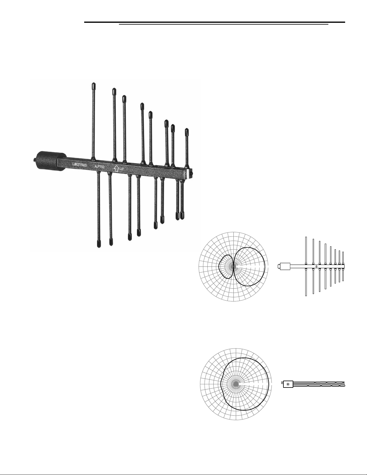
The ALP700A antenna is an LPDA (Log Periodic Dipole
Array) design that provides a useful directional pattern
over a broad frequency bandwidth. Most “gain antennas”
(those designs with a directional pattern) are limited in
bandwidth. This makes them awkward for use in multichannel wireless systems and with frequency agile
wireless systems.
The broad bandwidth of the ALP700A covers the entire
UHF band used for Lectrosonics wireless microphone and
IFB systems, yet still provides the directional pattern
needed to cover long distances.
The antenna is constructed of machined aluminum finished in electrostatic powder coat for lasting ruggedness.
Elements (rods) are user replaceable with simple tools.
The antenna is supplied with a stainless mounting stud
that adapts it to an optional adapter kit. The adapter kit
provides a variety of mounting options.
o
120
150
o
180
210
240
90
270
60
30
-20
-25
-15
-10
300
o
o
-5
10
50
0
330
UP
Typical Vertical Pattern
o
90
60
30
-20
-25
-5
-15
-10
o
10
50
0
330
180
120
150
o
210
240
270
300
o
Typical Horizontal Pattern
Page 2
Orientation and Usage
The smaller rod elements of the antenna should
be pointed toward the matching transmitter for
maximum sensitivity (note the pattern plots on the
first page).
Since a wireless transmitter antenna is generally
oriented vertically, the rod elements on the
ALP700A should also be oriented vertically. Note
the “up” arrow engraved on the boom of the antenna.
The optional mounting adapters permit a wide
variety of orientations. It is important to locate the
antenna at least a foot or two (or more) away from
nearby surfaces. Reflections from nearby surfaces can alter the pattern and/or affect the
sensitivity of the antenna to certain frequencies in
particular locations.
The coaxial cable connected to the antenna should
be routed away from the antenna.
The antenna is terminated with a 50 Ohm BNC connector. The BNC
jack is connected to a coaxial line inside the boom opposite the jack.
A 3/8” - 16 threaded mounting stud is supplied to fit the adapters in the
optional mounting adapter kit. Two different threaded sockets are
available, positioned at 90 degrees from one another to allow horizontal or vertical mounting.
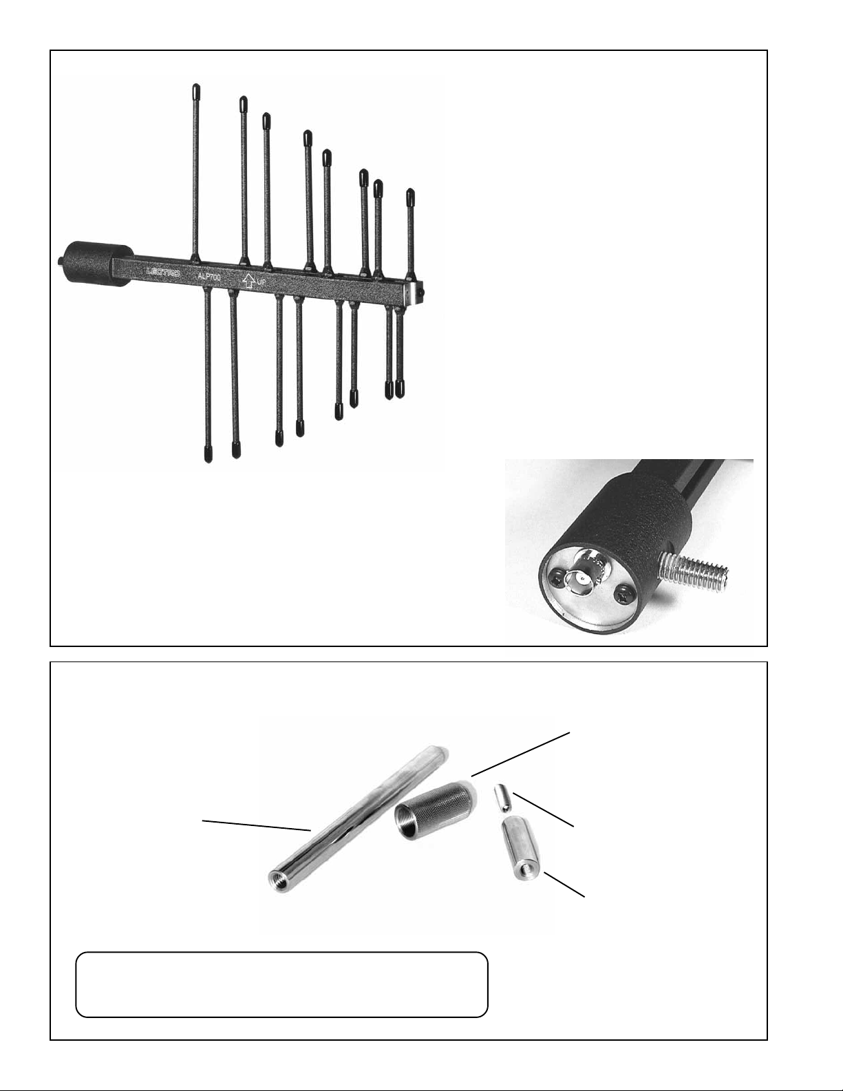
Optional Mounting Adapter Kit
Threaded adapter for standard
lighting clamps. 1/2” diameter
x 6 inch long. 3/8”-16 thread
on both ends.
Four piece kit model: ALPKIT
The mounting adapter kit allows mounting on photo and video
tripods, lighting equipment, and standard microphone stands.
The parts are constructed of stainless steel for lasting durability.
Microphone stand adapter,
1 1/2” long. 5/8”- 27 thread
on one end, with 3/8”-16
thread in other end. Knurled
finish.
1/4” - 20 threaded adapter.
Threaded adapter for photo/
video tripod mounting. 1/2” diameter x 1 3/4” long. 3/8”-16
thread on one end, 1/4”-20 on
the other end.
Page 3

A
h
Overall Length to Cut Rods
Rod #1 (shortest) 2.840”
Rod #2 3.066”
Rod #3 3.335”
Replacement of Elements
The rod elements of the antenna are secured to the booms with hex nuts.
To replace an element, unscrew the nut and remove the threaded end of
the rod.
The repair kit includes a full length rod, hex nut and plastic cap. Remove
the nut and plastic cap for measurement and cutting.
The length of each element is critical to ensure maximum performance of
the antenna. Measure the overall length accurately and cut off the nonthreaded end of the rod to the exact length shown in the table below.
Cut off this end
to length listed in table
Rod #4 3.915”
Rod #5 4.450”
Rod #6 4.990”
Rod #7 5.440”
Rod #8 (longest) 5.875”
Cross Section/End View
Threaded holes
for rods
+/- .011" accuracy
ttach hex nut after rod is cut to lengt
Coaxial line
Internal
brass rod
The BNC jack on the end of the antenna connects
to a coaxial line inside one of the rails. The
coaxial line is formed by a brass rod that runs
through a tunnel in the center of the rail.
Adjust the hex nut close to the end of the threads
as shown. Screw the replacement rod into the
threaded hole in the rail.
Page 4

Adjustment of Element Length
Accurately measure the length from the edge
of the boom (not the hex nut) to the end of the
metal rod. Adjust the rod to the exact length
shown in this drawing.
When the exact length has been set, hold the rod
in place and tighten the hex nut to secure the rod.
Measure the length again to ensure accuracy.
5.660
.225
5
.775
35
4
00
4.2
3.7
.120
3
50
25
.8
.6
2
2
Install plastic cap onto rod end after the length
has been adjusted and hex nut is tightened.
Specifications
ALP700A
5.660
UP
.775
5.225
4
500 - 800 MHz
.700
3
.235
4
.120
3
.625
2
2.850
Gain: +7dBi (isotropic)
+4dBi over dipole
Range: 500-800 MHz
Weight: 15.6 ozs
Connector: 50 ohm BNC
Dimensions: 13.5” long x 12.25” wide
ALP700ATD-0705
581 Laser Road NE • Rio Rancho, NM 87124 USA • www.lectrosonics.com
(505) 892-4501 • (800) 821-1121 • fax (505) 892-6243 • sales@lectrosonics.com
 Loading...