

Page 1
ALP Series
TECHNICAL DATA
LPDA Antennas
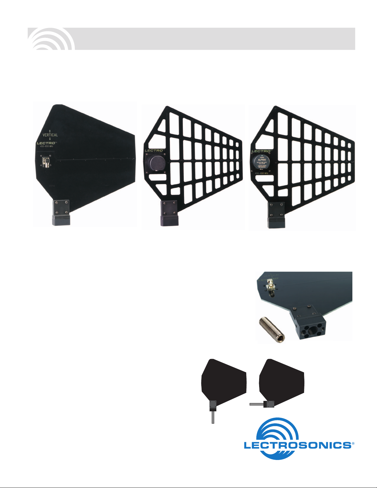
ALP500 ALP620 ALP650 Series
Economical design ideal for
fixed applications
Skeletal design for decreased
wind loading
Onboard amplifier ideal for
long cable runs, phantom
powered from Venue,
UMC16 or Bias T
The ALP Series antennas are a Log Periodic Dipole
Array (LPDA) design that provides a useful directional
pattern over a broad frequency bandwidth. Many “gain
antennas” (those designs with a directional pattern) are
limited in bandwidth, making them awkward for use in
multi-channel wireless systems and with frequency agile
wireless systems. With VSWR below 2:1 from 450 to 862
MHz, the broad bandwidth of the ALP Series covers a
broad section of the band used for Lectrosonics wireless
microphone and IFB systems, yet still provides the directional pattern needed to cover long distances.
All ALP Series antennas are constructed of 1/8” FR4
fiberglass circuit board material and are extremely rugged. The ALP620 and ALP650 Series antennas include
a protective cover over the BNC connector, making them
suited for field production, while the more economical ALP500 is better suited for indoor installation. The
perforated body of the ALP620 makes it resistant to wind
loading outdoors. The ALP650 models are “receive only”
models, featuring a built-in amplier with adjustable gain
for use with long coaxial cable runs and/or RF splitters.
The antennas can be mounted horizontally or vertically
by removing four screws and repositioning the mount-
ing block. This helps to position the antenna away from
nearby reective surfaces to preserve more of the natu-
ral pattern of the LPDA design.
Versatile Mounting Block
The mounting block on all ALP Series antennas can
accept three common sizes of threads:
• 1/4”-20 (tripod
mount)
• 3/8”-16 (pro
tripod mount)
• 5/8”-27 (mic
stand)
A 3/8”-16 stud (Part
#28769) is included
with all ALP Series
antennas.
The mounting
block can be
rotated to allow
horizontal
or vertical
mounting
Rio Rancho, NM, USA
www.lectrosonics.com
Page 2
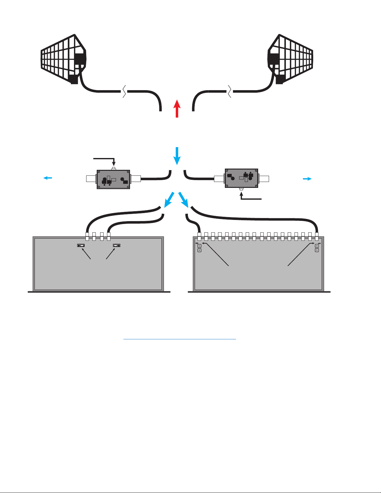
ALP650
Powering the ALP650
DC power is supplied to the
amplifier through the connected
coaxial cable from a BIAS T,
UMC16B or VENUE receiver.
DC POWER TO ALP650
RF OUT
ALP650
The BIAS T connects external
DC power to the antenna, blocks
the DC from its output to pre-
vent it from entering the receiver
antenna ports and passes the
RF output of the antenna to the
receiver.
9 to 16 VDC
RF OUT
BIAS T
ANT AANT B
Antenna Power Jumpers
VENUE RECEIVER
The VENUE receiver also includes
a DC power pass-through to operate
the ALP650 antenna amplier. Jump-
ers on the circuit board enable and
disable the DC power.
NOTE: The three examples shown above are
mutually exclusive. Only one of them should be
used in each installation.
OR
BIAS T
RF OUT
9 to 16 VDC
ANT A
Antenna Power Jumpers
ANT B
UMC16B MULTICOUPLER
The UMC16B multicoupler passes DC
power from its supply to the antenna
input ports to power the ALP650
through the coaxial cable. Jumpers on
the circuit board enable or disable the
DC power.
Page 3

Active jumper
Adjusting Gain on the ALP650 Amplifier
In cases where the antenna is feeding a long coaxial
cable run and/or a splitter, additional gain is generally
needed. The goal is to compensate for the loss through
the cabling and deliver a signal level equivalent to connecting the antenna directly to the receiver. Too much
gain adds unnecessary noise and some risk of increasing IM (intermodulation) in the receiver. Too little gain
runs the risk of dropouts in the reception.
Three jumpers are provided to adjust the gain from the
built-in amplier:
Jumper Value Attenuation Resulting Gain
0 0 dB 12 dB
-4 4 dB 8 dB
-7 7 dB 5 dB
Add up the loss caused by long coaxial cable runs,
antenna splitters, etc. and set the gain as closely as
possible to the total loss. For example, consider a 4-way
passive splitter such as the ZFSC41 with 6 db of loss
at each output and a coaxial cable such as the ARG15
with 2 db of loss, for a total loss of 8 dB. In this case,
the amplier should be used with the 4 dB attenuator to
produce the needed 8 dB of gain (12 - 4 = 8). One of the
jumpers must be in the active position at all times.
Store other jumpers here
Optional Mounting Adapter Kit
Threaded adapter
for standard lighting
clamps. 1/2” diameter
x 6 inch long. 3/8”-16
thread - both ends.
(PART # 26311-1)
Threaded adapter for
photo/video tripod
mounting. 1/2” diameter
x 1 3/4” long. 3/8”-16
thread on one end, 1/4”-
20 on the other.
(PART # 26312-1)
Microphone stand adapter, 1
1/2” long. 5/8”- 27 thread on one
end, with 3/8”-16 thread in other
1/4” - 20 threaded adapter
(PART # 28770)
(part # ALPKIT)
end. Knurled finish.
(PART # 26313-1)
Optional Accessories
Mini-Circuits passive splitters: Loss:
ZSC24 (2-way) 3.4 dB
ZSC41 (4-way) 6.8 dB
ZSC843 (8-way) 10.2 dB
Coaxial Cables: Loss:
ARG2 (2 ft. RG-8/X - Belden 9258) .25 dB
ARG2RT (2 ft. RG174/U - Belden 8216) .50 dB
(right angle connectors)
ARG15 (15 ft. RG-8/X - Belden 9258) 1.4 dB
ARG25 (25 ft. RG-8/U - Belden 9913F) 1.9 dB
ARG50 (50 ft. RG-8/U - Belden 9913F) 2.8 dB
ARG100 (100 ft. RG-8/U - Belden 9913F) 4.6 dB
ARX125 (125 ft. RG-8/X - Belden 9258) 12.5 dB
Page 4

Orientation
A wireless transmitter antenna is generally oriented vertically, therefore, the ALP should also be oriented verti-
cally. The transmitter antenna should be parallel with the
plane of the ALP antenna as depicted below.
Typical Horizontal Pattern
Typical Vertical Pattern
Specifications
ALP500, ALP620
Pattern Gain: +7dBi (isotropic)
+4dBd (over dipole)
Range: 450-862 MHz
Weight: ALP500: 14.2 oz.
ALP620: 9.4 oz.
ALP650/E Series: 12 oz.
Connector: 50 Ohm BNC
Dimensions: 12” high x 10.5” deep x 1.5” wide
(ALP650 without mounting hardware)
ALP650 Series with RF Amplifier
Pattern Gain: +7dBi (isotropic)
+4dBd (over dipole
Passband:
ALP650L/E (RoHS compliant) 470.000 - 692.000 MHz
ALP650M/E (RoHS compliant) 537.000 - 768.000 MHz
ALP650H/E (RoHS compliant) 640.000 - 862.000 MHz
RF Gain: +12 dB with 0dB attenuator
+8 dB with 4dB attenuator
+5 dB with 7dB attenuator
Third Order Intercept: +27 dBm @ input (+41 dBm output)
Weight: 12 oz. (all versions)
Power Requirements: 8V to 16V DC at the input jack;
auto reset poly fuse protection circuit;
constant power switching supply
• 8V DC (125 to 145 mA)
• 12V DC (83 to 106 mA)
• 14.4V DC (69 to 89 mA)
• 16V DC (60 to 80 mA)
Phantom Powering: DC voltage supplied via coaxial cable by
UMC16B,
VRM input jack or BIAS-T power inserter
(70 to 80 mA)
Power Consumption: 1.2 Watt nominal (switching regulator)
The ALP650 Series antennas have been tested and
found to comply with the limits for a Class B digital device, pursuant to Part 15 of the FCC Rules. These limits
are designed to provide reasonable protection against
harmful interference in a residential installation. However,
there is no guarantee that interference will not occur in a
particular installation. The antenna generates, uses and
can radiate radio frequency energy and, if not installed
and used in accordance with the instructions, may cause
interference to radio receivers. Changes or modications
to this equipment not expressly approved by Lectrosonics, Inc. could void the user’s authority to operate it.
581 Laser Road NE • Rio Rancho, NM 87124 USA • www.lectrosonics.com
(505) 892-4501 • (800) 821-1121 • fax (505) 892-6243 • sales@lectrosonics.com
If this equipment does cause harmful interference to
radio or television reception, which can be determined by
turning the equipment off and on, the user is encouraged
to try to correct the interference by one or more of the
following measures:
• Reorient or relocate the receiving antenna
• Increase the separation between the equipment
and receiver
• Connect the equipment into an outlet on a circuit
different from that which the receiver is connected
• Consult the dealer or an experienced radio/TV
technician for help
Applies to:
ALP650L/E, ALP650M/E
and ALP650H/E
25 September 2012
 Loading...