

Page 1
ALP600
LPDA Antenna
TECHNICAL DATA
Feature Highlights
• Extremely rugged “shark fin” design
• SWR below 2:1 from 450 to 850 MHz
• Ideal for portable applications
• 50 ohm BNC connector
• 3/8” x 16 threaded stainless steel mounting
stud included
• Ceiling, floor or wall mounting options
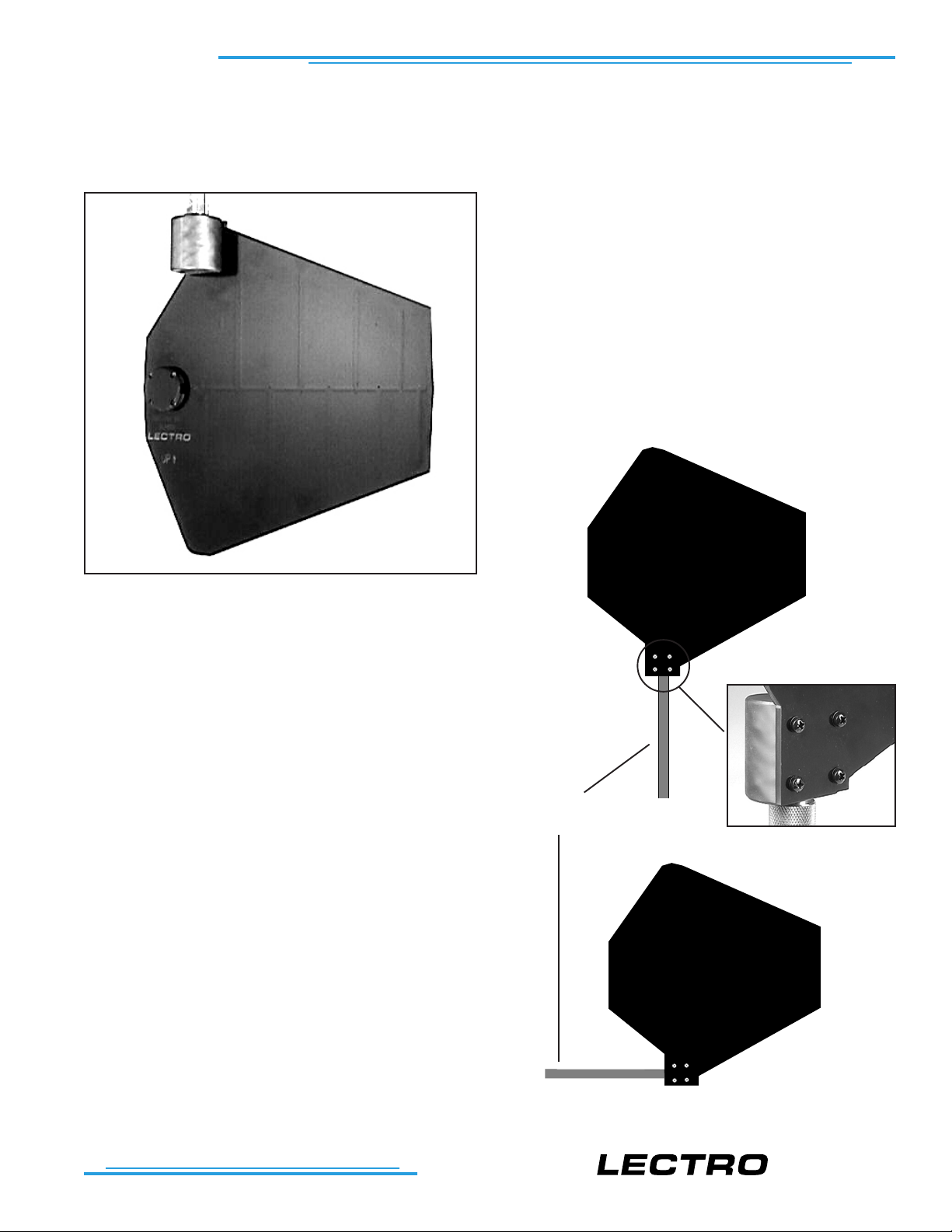
The ALP600 antenna is a Log Periodic Dipole Array
(LPDA) design that provides a useful directional pattern
over a broad frequency bandwidth. Most “gain antennas” (those designs with a directional pattern) are limited
in bandwidth. This makes them awkward for use in
multi-channel wireless systems and with frequency agile wireless systems.
The broad bandwidth of the ALP600 covers the entire
UHF band used for Lectrosonics wireless microphone
and IFB systems, yet still provides the directional pattern needed to cover long distances.
The ALP600 antenna is constructed of 1/8” FR4 fiberglass board and is extremely rugged. This antenna is
best suited for portable applications including temporary setups for field shoots. It is not intended to be left
outdoors permanently.
A sturdy aluminum housing protects the 50 ohm BNC
connector. There is also an optional adapter kit that
provides a variety of mounting options.
The ALP600 can be mounted on horizontal or vertical
surfaces by removing four screws and repositioning the
mounting block. Orientation of the threaded adapter in
any other position than what is shown here may interfere with the normal operation of the antenna.
Also it is important to locate the antenna at least a foot
or two away from nearby surfaces. Reflections from
nearby surfaces can alter the pattern and/or affect the
sensitivity of the antenna to certain frequencies.
threaded
adapter
Remove screws and rotate
block to change orientation
T M
Page 2
maximum sensitivity
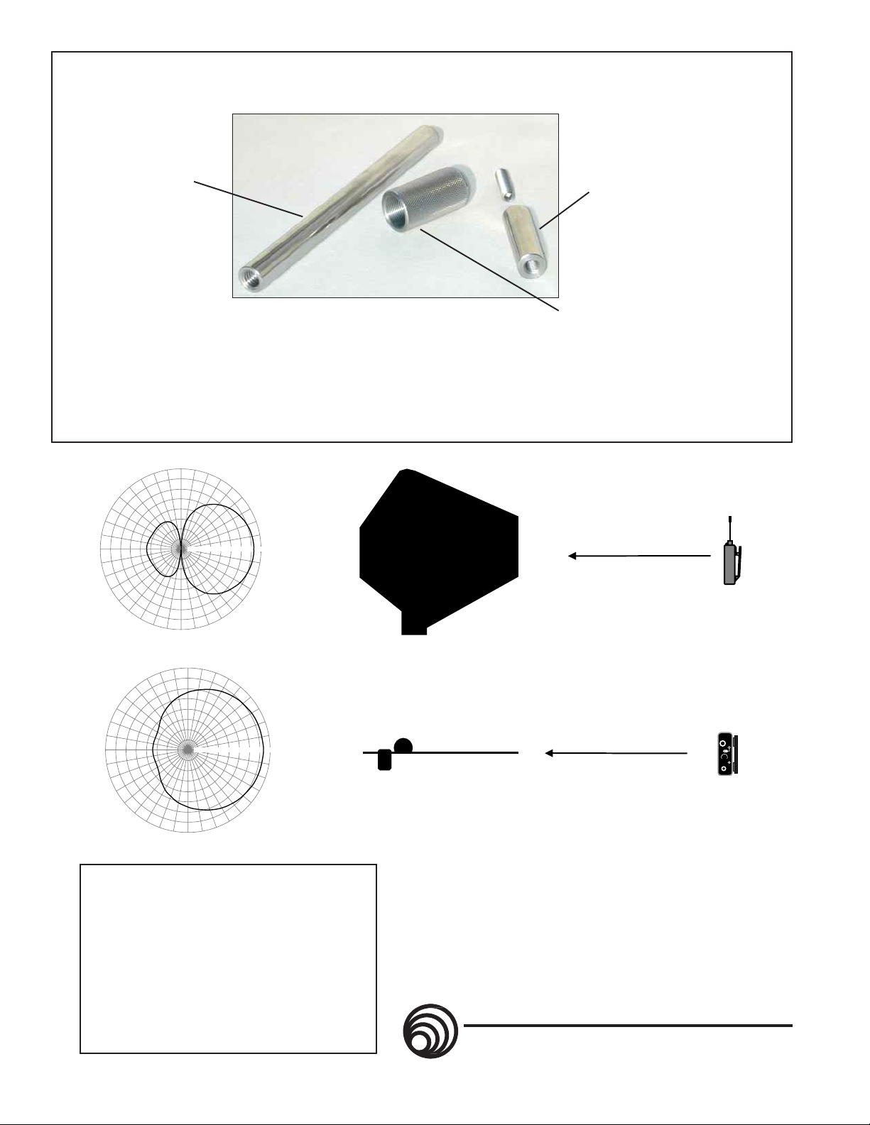
Optional Mounting Adapter Kit
10
50
-5
-10
-20
-25
o
10
50
-5
-10
-20
-25
o
Threaded adapter for
standard lighting clamps.
1/2” diameter x 6 inch long.
3/8”-16 thread - both ends.
o
120
90
60
Threaded adapter for photo/video
tripod mounting. 1/2” diameter x 1
3/4” long. 3/8”-16 thread on one
end, 1/4”-20 on the other.
Microphone stand adapter.
5/8”- 27 thread with 3/8”-16 thread
in other end x 1 1/2” long.
A mounting adapter kit is available (part # ALPKIT) that
contains three adapters threaded to fit the stud supplied with
the antenna. The kit allows mounting on photo and video
tripods, lighting equipment, and standard microphone stands.
Constructed of stainless steel for lasting durability.
o
180
180
150
210
-15
240
120
150
o
210
240
o
270
o
90
o
270
30
0
330
300
60
30
-15
300
0
330
Specifications
Gain: +7dBi (isotropic)
Range: 450-850 MHz
Weight: 15.6 ozs
Connector: 50 ohm BNC
Dimensions: 13.5” long x 12.25” wide
+4dBd (over dipole)
10.75” x 11” tall
Typical Vertical Pattern
Typical Horizontal Pattern
ORIENTATION
A wireless transmitter antenna is generally oriented vertically, therefore, the ALP600 should also
be oriented vertically. Note the “up” arrow on the
antenna. The transmitter antenna should be parallel with the plane of the ALP600 antenna as
depicted above.
LECTROSONICS, INC.
581 Laser Rd. NE - Rio Rancho, NM - 87124 USA
(505) 892-4501 (800) 821-1121 Fax(505) 892-6243
www.lectrosonics.com sales@lectrosonics.com
maximum sensitivity
ALP600-0400
 Loading...