

Lectronix T7000 Installation Instructions Manual
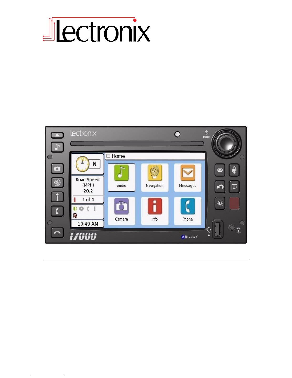
T7000
Installation Instructions
Read these instructions carefully before installing this product and keep this manual for
future reference.

© 2008 Lectronix, Inc.
Part Number – 19221-A.0

DISCLAIMER
THIS IS A DISCLAIMER OF LIABILITY AND DAMAGE RESPONSIBILITY AS REGARDS TO
LECTRONIX, INC. RELATING TO YOUR USE OF THE LECTRONIX T7000 SYSTEM. READ
IT CAREFULLY. YOU ASSUME TOTAL RESPONSIBILITY AND RISK FOR USING THIS
SYSTEM.
Failure to properly focus on the operation of your motor vehicle can result in death,
serious injury and property damage. This T7000 device should never be used at a time or
in a manner that distracts you from properly focusing on operation of the motor vehicle in
which it is installed. Our concern is for your safety. We ask that you fully cooperate with
and share that concern.
Always operate the vehicle in a safe manner and in full compliance with speed limits, road
safety signs and all other laws and devices which regulate operation of a motor vehicle.
Be and remain aware of driving conditions at all times when using this system while
operating a motor vehicle.
Operation of this unit, including its camera, navigation, audio and other features can be
distracting to your operation of the motor vehicle. While the system is intended to provide
both entertainment and helpful vehicle and navigation information, it is not intended to,
nor should you allow it to distract you from properly focusing on operating the motor
vehicle in which it is installed. It is up to you to minimize or prevent such distraction.
Learn how to use this system before placing the vehicle in operation. Minimize the amount of
time spent viewing the screen of the unit while driving and use voice prompts whenever possible.
Do not attempt to adjust settings of the system or resolve any malfunction with it while driving.
Instead, pull off the road in a safe and legal manner and then adjust its settings or deal with any
malfunction. In the event of malfunction, disable the unit (turn power off or remove power from
the system).
In addition to its multiple other functions, your T7000 system is equipped with a navigation
function. When navigating, carefully compare information displayed on the unit to all available
navigation sources, including information from street signs, visual sightings, and maps. Do not
enter destinations, change settings or access any functions requiring prolonged use of the
controls of the unit while operating your motor vehicle. For safety, pull off the road before making
any adjustments to the system or resolving any navigation discrepancies or questions.

Table of Contents
Safety Information ......................................................................................................................... 1
Warnings ...................................................................................................................................... 1
Cautions ....................................................................................................................................... 2
Notes on Use: Liquid Crystal Display Panel and Touch Screen. ................................................. 2
Overview ......................................................................................................................................... 3
Unit Mounting ................................................................................................................................. 3
Cameras .......................................................................................................................................... 4
Selecting a mounting location ...................................................................................................... 4
Side Cameras ........................................................................................................................... 4
Rear Camera ............................................................................................................................ 4
Flir Camera............................................................................................................................ 4
Mounting Cameras ....................................................................................................................... 5
Direct Mounted Side Cameras ................................................................................................. 5
Bracket Mounted Side Cameras .............................................................................................. 6
Rear Camera ............................................................................................................................ 7
Camera Cable Routing ................................................................................................................ 8
GPS and Satellite Antenna ........................................................................................................... 9
Determining the Mounting Location ............................................................................................. 9
Antenna cable routing .................................................................................................................. 9
Microphone mounting ................................................................................................................. 10
Choosing a mounting location .................................................................................................... 10
Microphone Cable Routing ........................................................................................................ 10
TPMS antenna mounting ............................................................................................................ 10
Selecting a Mounting Location ................................................................................................... 10
Mounting the TPMS Antenna ..................................................................................................... 10
Routing the TPMS antenna cable .............................................................................................. 11
iPod Dock ..................................................................................................................................... 11
Connecting The System .............................................................................................................. 11
Power/Speakers ......................................................................................................................... 11
Testing for Proper Connection of Power and Speakers ......................................................... 12
J1939 Communications bus ......................................................... Error! Bookmark not defined.
Testing For Proper J1939 Operation ...................................................................................... 12
Cameras ..................................................................................................................................... 13
Turn and Reverse Signals ......................................................................................................... 13
Testing the Turn and Reverse Signals ................................................................................... 13
GPS and Satellite Radio Antennas ............................................................................................ 14
Testing the Antenna Installation ............................................................................................. 14
Microphone ................................................................................................................................ 15
Testing the Microphone .......................................................................................................... 15
iPOD Dock ................................................................................................................................. 15
Testing the iPOD dock ........................................................................................................... 15
Troubleshooting .......................................................................................................................... 16
If You Suspect Something is Wrong .......................................................................................... 16
Common Problems .................................................................................................................... 16
Appendix D: T7000 Technical Specifications ........................................................................... 18
Appendix A: T7000 Connector Definitions ............................................................................... 19
Vehicle Power, Audio & I/O (VEH/SPKR/IO) ............................................................................. 19
Audio Line In (front) ................................................................................................................... 20
USB (front) ................................................................................................................................. 20
USB (rear) .................................................................................................................................. 20
AM/FM Antenna Connector (AM/FM/WB) ................................................................................. 20
TPMS Antenna Connector (TPMS)............................................................................................ 21
GPS Antenna (GPS) .................................................................................................................. 21
Internal Satellite Module ( int SDAR) ......................................................................................... 21

External Satellite Module (ext. SDAR) ....................................................................................... 21
Video (VIDEO) ........................................................................................................................... 21
Microphone & Vehicle Input/Output (mic & IO) .......................................................................... 22
Qualcomm Interface (QUALCOMM) .......................................................................................... 22
iPod Interface (IPOD) ................................................................................................................. 22
IMPORTANT SAFETY INFORMATION
1
Warning
This symbol intends to alert you to the presence of
important operation instruction and installation
instructions. Failure to heed the instructions may result
in severe injury or death.
Caution
This symbol intends to alert you to the presence of important
operation instruction and installation instructions. Failure to
heed the instructions may result in injury or material damage.
Warning
Observe the following warnings when using
this unit.
The driver should not operate the system while driving.
Operating the system will distract the driver from looking ahead of the vehicle and can
cause accidents. Always stop the vehicle in a safe location and use the parking brake
before operating the system.
Use the proper power supply.
This product is designed for operation with a negative grounded 12 V DC battery system.
Never operate this product with other battery systems, especially a 24 V DC battery
system.
Protect the CD Player mechanism.
Do not insert any foreign objects into the slot of this unit.
Do not disassemble or modify the unit.
Do not disassemble, modify the unit or attempt to repair the product yourself. If the
product needs repair, consult your dealer or contact technical support (see Appendix B).
Do not use the unit when it is not functional.
If the unit is not functional (no power, no sound) or in an abnormal state (has foreign
objects in it, is exposed to water, is smoking, or smells), turn it off immediately and
consult your dealer.
Refer installation to qualified personnel.
Safety Information
Read the operating instructions for the T7000 and all other components of the system carefully
before using the system. They contain instructions about how to use the system in a safe and
effective manner. FAILURE TO OBSERVE THE INSTRUCTIONS GIVEN IN THIS MANUAL
MAY CAUSE INJURY OR DAMAGE AND VOID THE WARRANTY.
This manual uses symbols to show you how to use the product safely and to alert you to potential
dangers resulting from improper connections and operations. The meanings of the symbols are
explained below. It is important that you fully understand the meanings of the symbols in order to
use this manual and the system properly.
Warnings
IMPORTANT SAFETY INFORMATION
2
Caution
THE CD PLAYER IS A CLASS I LASER PRODUCT.
USE OF CONTROLS OR ADJUSTMENTS OR
PERFORMANCE OF PROCEDURES OTHER THAN THOSE
SPECIFIED HEREIN MAY RESULT IN HAZARDOUS
RADIATION EXPOSURE.
DO NOT OPEN COVERS AND DO NOT REPAIR BY
YOURSELF. REFER SERVICING TO QUALIFIED
PERSONNEL.
Cautions
Notes on Use: Liquid Crystal Display Panel and Touch Screen.
The T8065 display is a Liquid Crystal Panel, commonly known as an LCD. Over the surface of
the LCD is a Touch Screen to allow the user to touch the screen and activate buttons and other
controls. There are a number of considerations to keep in mind with any system using an LCD
panel. The Touch Screen is also vulnerable to damage if it is not properly used. While both
elements can take substantial use, they need to be treated with care. The following guidelines
should be followed when using your unit. Refer to the Maintenance section of this manual for
cleaning instructions.
Do not cause impact to the liquid crystal panel/touch screen.
Do not use a mechanical pointer to touch the screen as it may damage the touch screen.
Always use your finger so you can feel how much pressure is being applied to the
screen.
When the temperature is very cold or very hot, the image may appear unclear or may
move slowly.
In order to protect the liquid crystal panel, keep it out of direct sunlight while the unit is not
in use.
Sudden changes in the temperature inside the vehicle such as those which occur
immediately after the vehicle’s air conditioner or heater has been turned on may cause
condensation (droplets of water) to form and, as a result, the panel may not work
properly. Do not use the unit while these symptoms are in evidence but leave the unit
standing for about an hour, and then resume or start use.

3
Overview
Installation of a T7000 system is straight forward, consisting of mounting the unit, mounting and
routing the GPS and Satellite Radio antennas, mounting and routing the cameras and cables,
mounting the microphone and routing the cable, mounting the Tire Pressure antenna and routing
the cable and connecting the system to all wiring. If the optional iPOD dock cable is used, a
suitable place to mount the dock is required.
Mounting of the various components will vary depending on the configuration of the truck, metal
or fiberglass cab structures and what options are installed. This instruction manual gives general
guidelines that can be applied to any installation. For specific truck wiring (wire locations and
functions), consult your truck dealer, service manual, service center or manufacturer.
Unit Mounting
A mounting “bucket” is available for the Freightliner Cascadia that allows direct mounting into the
dash. To install the T7000 and mounting bucket, follow these steps:
1. Remove the dash trim panel and dash top access panel, exposing the original radio
mounting bucket.
2. Remove the original radio.
3. Remove and retain the screws holding the original radio bucket in the dash.
4. Insert the new T7000 bucket into the dash and secure with the screws from the original.
5. Insert the T7000 into the new bucket once all cables have been connected.

4
Cameras
The T7000 supports up to four cameras on the vehicle and is compatible with the following
models:
Sony CHSV2-01D (left/drivers side)
Sony CHSV2-01P (right/passenger side)
Sony VCB-RV2MH (rear)
Flir forward looking infrared camera
Selecting a mounting location
Side Cameras
The optional side camera’s need to be mounted on each side of the truck to give the driver a
clear view of the area beside the truck. In general, select a mounting location as far forward as
possible to allow an unobstructed view of the side of the truck and where they will not interfere
with entrance doors, hood opening and other truck features. Common mounting locations include:
Fender in front of the cab door but behind the wheel well
Running board beside/below the cab
Other convenient places on the side of the truck that avoids interference of the driver
entering and exiting the truck.
Depending on the available locations and contours of the truck, it may be necessary to mount the
camera on a bracket which is attached to the truck instead of directly on the truck. If this is
necessary, the bracket should be made from material that will not corrode or discolor. Aluminum
is a good choice as it requires no painting, will not rust, and is more easily bent than steel. Insure
that whatever material is used, it is thick enough to prevent the camera from vibrating while the
vehicle is in motion. Before permanently mounting the camera it is advisable to connect it to the
T7000 system and check the view to insure that the viewing area is as desired.
Rear Camera
The optional rear camera should be mounted on the rear of the cab where it will have a clear view
of the rear of the tractor including the axles and trailer mount. Consideration should also be given
to a location where the camera cable can easily be routed inside the vehicle. Choose a flat
surface near the top of the cab. Before permanently mounting the camera it is advisable to
connect it to the T7000 system and check the view to insure that the viewing area is as desired.
Flir Camera
The Flir camera is meant to be mounted on the front of the truck, facing forward giving a view
of the road. Suitable locations for the Flir would include:
The top edge of the cab
Front bumper or grill area
Front of the hood
It is advisable to connect the camera to the T7000 before permanent mounting to insure that the
view of the camera is as desired.
 Loading...