

Page 1
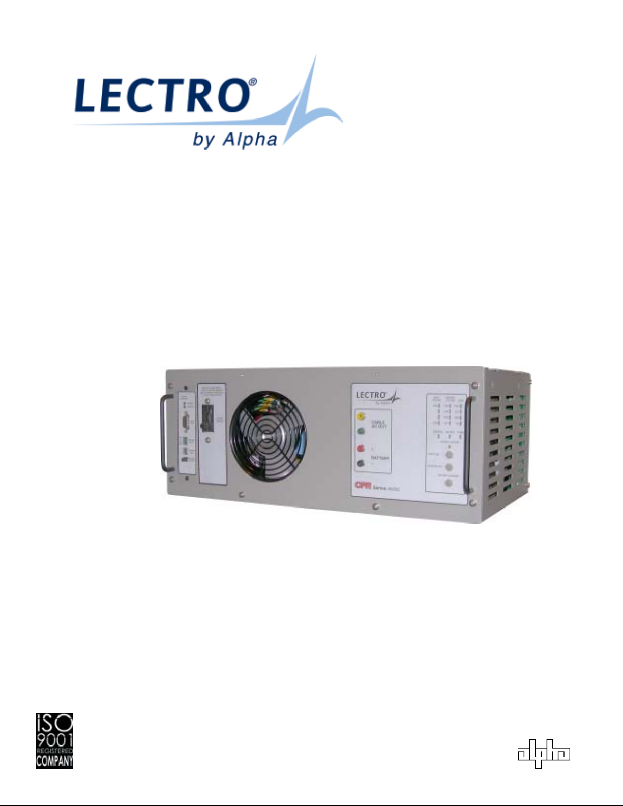
CPRTM
36VDC and 48VDC Technical Manual
Series Broadband Power Supply
Effective: March, 2004
®
Page 2

Alpha Technologies.
Power
Protecting The Power in Communications.
Page 3
TM
CPR
Series Broadband Power Supply Technical Manual
Effective: March, 2004
745-573-B0-001 REV. A — © 2004 Alpha Technologies
NOTE: Photographs contained in this manual are for illustrative purposes only. These
photographs may not exactly match your installation.
NOTE: Review the drawings and illustrations contained in this manual before
proceeding. If there are questions regarding the safe operation of this powering
system, please contact Alpha Technologies or your nearest Alpha
representative.
NOTE: Alpha denies responsibility for any damage or injury involving its enclosures,
power supplies, generators, batteries, or other hardware when used for an
unintended purpose, installed or operated in an unapproved manner, or
improperly maintained.
Contacting Alpha T echnologies:
For general product information and customer service
1-800-863-3930
(7:00 AM to 5:00 PM Pacific Time )
For complete technical support
1-800-863-3364
(7:00 AM to 5:00 PM Pacific Time, or 24/7 emergency support)
EC DECLARATION OF CONFORMITY
Units that are labeled with a CE mark comply with the following EU directives:
73/23/EEC Council Directive on equipment designed for use within certain voltage limits.
93/68/EEC Amending Directive 72/23/EEC.
89/336/EEC Council Directive relating to electromagnetic compatibility.
The EC Declaration of conformity is available upon request for products with a CE mark. For copies of
the EC Declaration of Conformity, contact Alpha Technologies.
Page 4

Preface
Important Safety Instructions...................................................................................................................... 6
General Safety Precautions ....................................................................................................................... 7
Battery Safety Notes .................................................................................................................................. 9
Battery Maintenance Guidelines .............................................................................................................. 10
Recycling and Disposal Instructions..........................................................................................................11
Electrical Safety.........................................................................................................................................11
Mechanical Safety.................................................................................................................................... 12
1.0 Overview
1.1 Introduction..................................................................................................................................... 13
1.2 Cabinet Nomenclature .................................................................................................................... 14
2.0 Cabinet Installation
2.1 Pole Mounting................................................................................................................................. 16
2.2 Ground Mounting............................................................................................................................ 18
2.3 Enclosure Grounding...................................................................................................................... 20
2.4 Electrical Connections .................................................................................................................... 21
Contents
3.0 Power Supply Installation
3.1 CPR™ Module Installation and Connection ................................................................................... 22
3.2 Battery Installation and Connection ................................................................................................ 25
3.2.1 48V Battery Installation Procedure ........................................................................................26
3.2.2 36V Battery Installation Procedure ........................................................................................27
3.2.3 Connecting an Additional 48V Battery String ......................................................................... 28
3.2.4 Connecting an Additional 36V Battery String ......................................................................... 28
3.2.5 Removing Batteries ............................................................................................................... 30
3.3 Operation........................................................................................................................................ 33
3.4 Maintenance ................................................................................................................................... 35
3.4.1 Routine Maintenance Checks................................................................................................35
3.4.2 CPR™ Power Supply Maintenance Log Sheet ..................................................................... 36
3.4.3 Battery Storage...................................................................................................................... 37
3.4.4 Proper Usage ........................................................................................................................ 37
3.4.5 Periodic Maintenance ............................................................................................................ 37
4.0 Troubleshooting
4.1 Troubleshooting Guide Part 1......................................................................................................... 38
4.2 Troubleshooting Guide Part 2......................................................................................................... 39
5.0 Status Monitoring
5.1 Installation ...................................................................................................................................... 40
5.2 Operation........................................................................................................................................ 41
5.3 Maintenance ................................................................................................................................... 42
6.0 Specifications
6.1 Electrical, Mechanical Specifications.............................................................................................. 43
4
745-573-B0-001 REV. A
Page 5

Figures & Tables
1.0 Overview
Fig. 1-1, Ground Mount (Front View of 4 battery cabinet with ground skirt)................14
Fig. 1-2, Pole Mount (Front View of 8 battery cabinet)................................................14
Fig. 1-3, Pole Mount (Rear View of cabinet) ...............................................................15
Fig. 1-4, Typical Placement of Disconnect Breaker on rear of Cabinet.......................15
Fig. 1-5, Coax “Feed Thru” Adapter Normal Location (Bottom Shelf) .........................15
2.0 Cabinet Installation
Fig. 2-1, Pole Mount Installation..................................................................................16
Fig. 2-2, Pad Dimensions............................................................................................19
Fig. 2-3, Enclosure Grounding ....................................................................................20
3.0 Power Supply
Fig. 3-1, Front panel layout (all models)......................................................................22
Fig. 3-2, Connection points for 60Hz, 15A units..........................................................24
Fig. 3-3, Connection points for 50Hz units ..................................................................24
Fig. 3-4, Connection points for 60Hz, 24A units..........................................................24
Fig. 3-5, 48V Battery Connections – Single String......................................................26
Fig. 3-6, 36V Battery Connections – Single String......................................................27
Fig. 3-7, 48V Battery Connections – Parallel Strings ..................................................28
Fig. 3-8, 36V Battery Connections – Parallel Strings ..................................................29
Fig. 3-9, 48V Parallel Battery Sense Wiring................................................................30
Fig. 3-10, 36V Parallel Battery Sense Wiring................................................................31
Fig. 3-11, 36V Single Battery Sense Wiring..................................................................32
Fig. 3-12, Front Panel Display ......................................................................................33
Fig. 3-13, Maintenance Log Sheet ................................................................................36
Preface
4.0 Troubleshooting
Table 4-1, Troubleshooting guide, Part 1.......................................................................38
Table 4-2, Troubleshooting guide, Part 2.......................................................................39
5.0 Status Monitoring
Fig. 5-1, CPRBattery Removal
6.0 Specifications
Table 6-1, Specifications................................................................................................43
Table 6-2, Specifications................................................................................................44
745-573-B0-001 REV. A
5
Page 6
Preface
Important Safety Instructions
Contained In This Manual.
Read This Manual Before Proceeding!
Review the drawings and illustrations contained in this manual before proceeding. If there are any questions
regarding the safe installation or operation of the system, contact Alpha Technologies or the nearest
Alpha representative. Save this document for future reference.
To reduce the risk of injury or death caused by electrical shock, explosion of fuel or moving parts; and to
ensure the continued safe operation of this product, the following symbols have been placed throughout
this manual. Where these symbols appear, use extra care and attention.
DANGEROUS VOLTAGE
This symbol indicates a “dangerous voltage” may exist in this area of the product. Use caution
whenever working in the area to prevent electrical shock.
INHALATION HAZARD - DON’T BREATHE VAPORS
This symbol indicates an “inhalation hazard” may exist in this area of the product. Use caution
whenever working in the area to prevent possible inhalation of harmful (fuel or exhaust) vapors.
NO MATCHES OR OPEN FLAMES
This symbol indicates a “fire or explosive hazard” may exist in this area of the product. Use
caution whenever working in the area to prevent possible combustion of fuel vapors.
MECHANICAL OR MOVING PARTS HAZARD
These symbols indicate a “mechanical or moving parts hazard” may exist in this area of the
product. Use caution whenever working in the area to prevent possible injury to the operator or
service personnel.
LEAK HAZARD
This symbol indicates a “leak hazard” may exist in this area of the product. Use caution whenever
working in this area to prevent and correct any leaks detected.
ATTENTION
This symbol indicates important installation, operation or maintenance instructions. Always
follow these instructions closely.
NOTE: Alpha Technologies’ products are subject to change through continual improvement
processes. Therefore, specifications and/or design layouts may vary slightly from
descriptions included in this manual. Updates to the manual will be issued when
changes affect form, fit or function.
6
745-573-B0-001 REV. A
Page 7

General Safety Precautions
A “Warning” identifies conditions and actions that pose a hazard to the user.
A “Caution” identifies conditions and actions that may damage the power supply or associated
equipment.
Warnings
NOTE: This enclosure and its associated hardware (power supply, batteries,
cabling) may contain equipment, batteries or parts which have accessible
hazardous voltage or currents.
To avoid injury:
• This enclosure and its associated hardware must be serviced by authorized personnel only.
• Enclosure must remain locked at all times, except when authorized service personnel are
present.
• Remove all conductive jewelry or personal equipment prior to servicing equipment, parts,
connectors,wiring, or batteries.
Preface
• Read and follow all installation, equipment grounding, usage, and service instructions
included in this manual.
• Use proper lifting techniques whenever handling enclosure, equipment, parts, or batteries.
• Batteries contain dangerous voltages, currents and corrosive material. Battery installation,
maintenance, service and replacement must be performed by authorized personnel only.
• Never use uninsulated tools or other conductive materials when installing, maintaining,
servicing or replacing batteries.
• Use special caution when connecting or adjusting battery cabling. An improperly connected
battery cable or an unconnected battery cable can result in arcing, a fire, or possible
explosion.
• A battery that shows signs of cracking, leaking or swelling must be replaced immediately by
authorized personnel using a battery of identical type and rating.
• Avoid any contact with gelled or liquid emissions from a valve-regulated lead-acid (VRLA)
battery. Emissions contain dilute sulfuric acid which is harmful to the skin and eyes.
Emissions are electrolytic, which are electrically conductive and are corrosive. Follow the
Chemical Hazards notes if contact occurs.
• Do not smoke or introduce sparks in the vicinity of a battery.
• Under certain overcharging conditions, lead-acid batteries can vent a mixture of hydrogen
gas which is explosive. Proper venting of the enclosure is required.
• Follow the battery manufacturer ’s approved transportation and storage instructions.
745-573-B0-001 REV. A
7
Page 8

Preface
General Safety Precautions
Cautions
NOTE: Enclosure, equipment or parts may be damaged or cause damage if used
or installed improperly.
To avoid damage:
• Prior to installation, verify that the AC input voltage to the enclosure and its equipment
match with respect to voltage and frequency.
• Prior to installation, verify that the output voltage from the enclosure or its equipment match
the voltage requirements of the connected equipment (load).
• Prior to installation, verify that the enclosure’s utility service panel is equipped with a
properly rated circuit breaker for use with the equipment inside. Refer to manufacturer’s
recommendations.
• Review and upgrade utility service panel circuit breaker requirements whenever the
equipment within the enclosure is changed.
• Prior to installation, contact local utilities, local building maintenance departments, and
cable/piping locator services to ensure that installation does not interfere with existing utility
or building cables/piping.
• Do not exceed the output rating of equipment. Verify load requirements prior and during
connection process.
• Prior to handling the batteries, touch a grounded metal object to dissipate any static charge
that may have developed on your body.
• Alpha Technologies is not responsible for unit damage due to enclosure or installation
temperatures which exceed the operating temperature of the product.
• The Lectro CPR UPS is a 36 or 48Vdc system designed for use with either a single or dual
string of three or four 12Vdc batteries. Please refer to Section 3 of this manual for more
details on proper battery installation, maintenance, storage, and replacement procedures
• Over current protection and disconnecting means for the AC output are to be supplied by the
electrical installer as required by local electrical codes.
• The operating temperature range for the Lectro CPR
intake of the CPR module.
®
UPS is –40°C to +55°C for air at the
• CPR UPS installations involving third-party cabinets, not supplied by Lectro or Alpha, require
adequate ventilation, airflow and spacing to ensure that the CPR® power supply operates
within a temperature range of -40°C to +55°C. Failure to provide an operating thermal
environment per published specifications will void the warranty.
8
745-573-B0-001 REV. A
Page 9

Battery Safety Notes
Lead-acid batteries contain dangerous voltages, currents and corrosive material. Battery installation,
maintenance, service and replacement must be performed by authorized personnel only.
Chemical Hazards
NOTE: Any gelled or liquid emissions from a valve-regulated lead-acid (VRLA) battery
contain dilute sulfuric acid, which is harmful to the skin and eyes.
Emissions are electrolytic, which are electrically conductive and corrosive.
To avoid injury:
• Servicing and connection of batteries shall be performed by, or under the direct supervision
of, personnel knowledgeable of batteries and the required safety precautions.
• Always wear eye protection, rubber gloves, and a protective vest when working near
batteries. Remove all metallic objects from hands and neck.
• Batteries produce explosive gases. Keep all open flames and sparks away from batteries.
Preface
• Use tools with insulated handles, do not rest any tools on top of batteries.
• Batteries contain or emit chemicals known to the State of California to cause cancer and
birth defects or other reproductive harm. Battery post terminals and related accessories
contain lead and lead compounds. Wash hands after handling. (California Proposition 65)
• Wear protective clothing (insulated gloves, eye protection, etc.) whenever installing,
maintaining, servicing, or replacing batteries.
• If any battery emission contacts the skin, wash immediately and thoroughly with water.
Follow your company’s approved chemical exposure procedures.
• If any battery emission contacts the eye, wash immediately and thoroughly with water for 10
minutes with pure water or a special neutralizing eye wash solution and seek immediate
medical attention. Follow your company’s approved chemical exposure procedures.
• Neutralize any spilled battery emission with the special solution contained in an approved
spill kit or with a solution of 1 lb. Bicarbonate of soda to 1 gallon of water. Report chemical
spill using your company’s spill reporting structure and seek medical attention if necessary.
• Always replace batteries with those of an identical type and rating. Never install old or
untested batteries.
• Do not charge batteries in a sealed container. Each individual battery should have at least
0.5 inches of space between it and all surrounding surfaces to allow for convection cooling.
• All battery compartments must have adequate ventilation to prevent an accumulation of
potentially dangerous gas.
745-573-B0-001 REV. A
9
Page 10

Preface
Battery Safety Notes, continued
y Prior to handling the batteries, touch a grounded metal object to dissipate any static
charge that may have developed on your body.
y Never use uninsulated tools or other conductive materials when installing, maintaining,
servicing or replacing batteries.
y Use special caution when connecting or adjusting battery cabling. An improperly
connected battery cable or an unconnected battery cable can make contact with an
unintended surface that can result in arcing, fire, or possible explosion.
y A battery showing signs of cracking, leaking, or swelling should be replaced immediately
by authorized personnel using a battery of identical type and rating.
y Under extreme overcharging conditions, Lead-acid batteries can vent a mixture of
Hydrogen gas which is explosive.
Battery Maintenance Guidelines
The battery maintenance instructions listed below are for reference only. Battery manufacturer’s
instructions for transportation, installation, storage or maintenance take precedence over these
instructions.
y To prevent damage, inspect batteries every 3 months for:
y Signs of battery cracking, leaking or swelling. The battery should be replaced
immediately by authorized personnel using a battery of the identical type and rating.
y Signs of battery cable damage. Battery cable should be replaced immediately by
Authorized Personnel using replacement parts specified by vendor.
y Loose battery connection hardware. Refer to battery manufacturer’s documentation for
the correct torque and connection hardware for the application.
y Apply battery manufacturer’s specified antioxidant compound on all exposed
connections.
y Verify battery terminals and/or exposed connection hardware is not within 2 inches of a
conductive surface. Reposition batteries as necessary to maintain adequate clearance.
y Clean up any electrolyte (battery emission) in accordance with all federal, state, and
local regulations or codes.
y Proper venting of the enclosure is recommended. Follow the Battery Manufacturer’s
approved transportation and storage instructions.
y Always replace batteries with those of an identical type and rating. Never install old or
untested batteries.
y Do not charge batteries in a sealed container. Each individual battery should have at
least 0.5 inches of space between it and all surrounding surfaces to allow for convection
cooling.
y All battery compartments must have adequate ventilation to prevent an accumulation of
potentially dangerous gas.
10
745-573-B0-001 REV. A
Page 11

Recycling and Disposal Instructions
y Spent or damaged batteries are considered environmentally unsafe. Always recycle
used batteries or dispose of the batteries in accordance with all federal, state and local
regulations.
Electrical Safety
y Lethal voltages are present within the power supply and electrical boxes. Never assume
that an electrical connection or conductor is not energized. Check the circuit with a volt
meter with respect to the grounded portion of the enclosure (both AC and DC) prior to
any installation or removal procedure.
y Do not work alone under hazardous conditions.
y A licensed electrician is required to install permanently wired equipment.
y Input voltages can range up to 240 VAC. Ensure that utility power is disabled before
beginning installation or removal.
y Ensure no liquids or wet clothes contact internal components.
Preface
y Hazardous electrically live parts inside this unit are energized from batteries even when
the AC input power is disconnected.
CAUTIONS
An agency-approved service disconnect switch is required at installation and shall be connected
between the utility power source and the CPRTM power supply. The service disconnect and service
disconnect installation is subject to local electrical codes and should be approved for application in a
NEMA 3R enclosure, rated 120/240V, with a non-interrupted neutral termination.
y For 120 VAC 60 Hz units, the service disconnect shall be a high-magnetic type circuit
breaker rated for 20 amperes in the line lead only.
y For 240 VAC units, the service disconnect shall be a 2 pole, high-magnetic type circuit
breaker rated for 15 amperes.
y For 220 VAC 60Hz and 230 VAC 50 Hz units, the service disconnect shall be a high-
magnetic type circuit breaker rated for 16 amperes in the line lead only.
y For 120 VAC 60 Hz units, use #12 AWG (minimum) copper, 75°C, for all utility input
wiring.
y For 240 VAC 60 Hz units, use #12 AWG (minimum) copper, 75°C, for all utility input
wiring.
y For 230 VAC 50 Hz units, use a minimum of 1.5 mm2 (#16 AWG copper, 75°C, for all
mains input wiring).
745-573-B0-001 REV. A
11
Page 12

Preface
Mechanical Safety
y Keep hands and tools clear of fans. Fans are thermostatically controlled and will turn on
automatically.
y Power supplies can reach extreme temperatures under load.
y Use caution around sheet metal components and sharp edges.
12
745-573-B0-001 REV. A
Page 13

1.0 Overview
1.0 Overview, Continued
1.1 Introduction
The Lectro CPR® Broadband Powering System is a result of an integrated approach that combines
proven line-interactive UPS technology with rugged ferro technology. The tradtional advantages of a
ferroresonant output, combined with high-capacity surge suppression, advanced microprocessor control,
improved thermal performance and greater operating efficiency provide for a lighter, smaller, and more
efficient unit.
This manual contains important instructions for the Lectro Uninterruptible Power Supply (UPS). These
instructions should be followed during installation and maintenance of the power supply, batteries,
cabinet, status monitor and any options and/or ancillary equipment.
The purpose of this manual is to provide the reader with the necessary information to install the
enclosure, the power supply, connect the battery strings, perform an initial turn up and test of the CPR
Power Supply, and to perform basic troubleshooting tasks.
Upon receipt of the system, verify the following:
The equipment has arrived undamaged.
All ordered options have arrived.
Before installation:
Verify the following:
• All necessary grounding rods and materials in place.
• Utility power run to site in accordance with the National Electric Code (NEC).
TM
745-573-B0-001 REV. A
13
Page 14
1.0 Overview, Continued
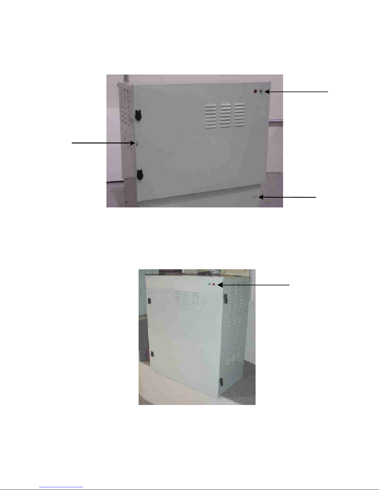
1.2 Cabinet Nomenclature
PADLOCK
HASP
EXTERNAL
INDICATOR
LAMPS
Fig. 1-1, Ground Mount (Front View of 4 battery cabinet with ground skirt)
EXTERNAL
INDICATOR
LAMPS
GROUND
SKIRT
Fig. 1-2, Pole Mount (Front View of 8 battery cabinet)
14
745-573-B0-001 REV. A
Page 15
1.2 Cabinet Nomenclature, continued
1.0 Overview, Continued
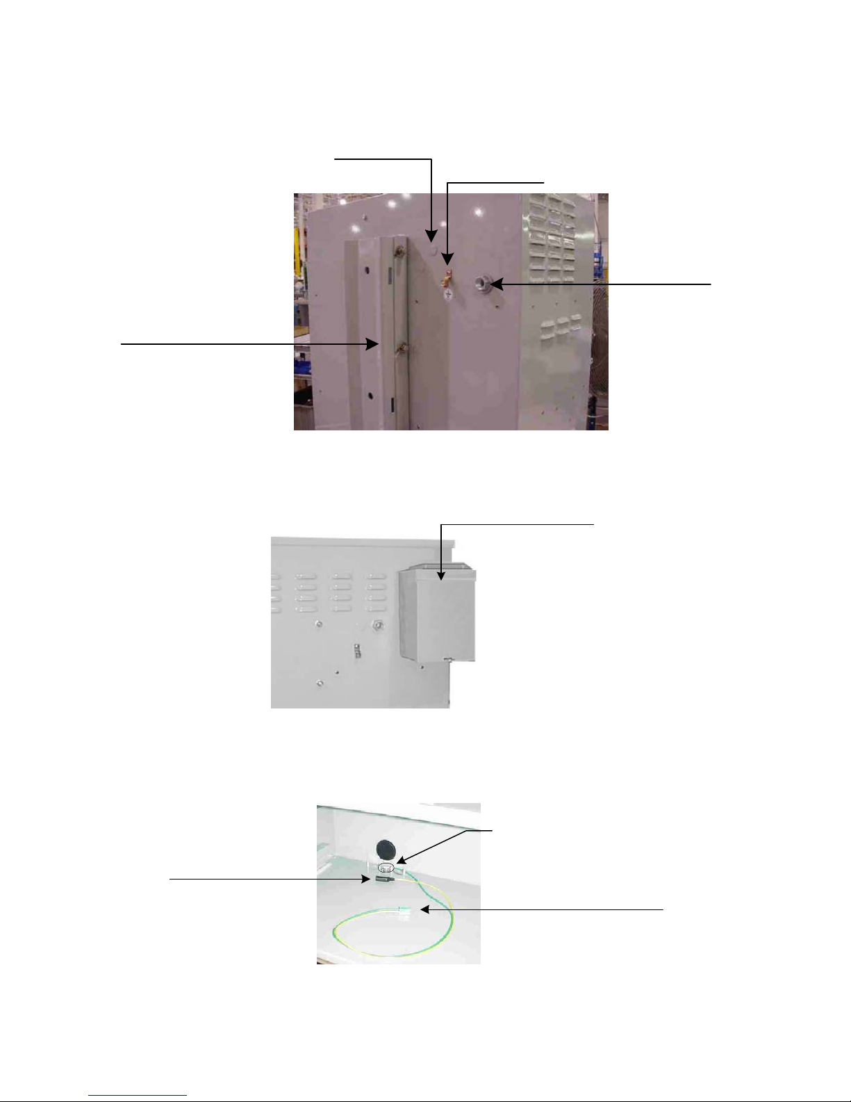
OPTIONAL
LOCATION FOR
"FEED-THRU" ADAPTOR
POLE MOUNTING
BRACKET
Fig. 1-3, Pole Mount (Rear View of cabinet)
GROUND
AC INPUT
CONDUIT
CONNECTION
DISCONNECT BREAKER BOX
Fig. 1-4, Typical Placement of Disconnect Breaker on rear of Cabinet
COAX SEIZURE CLAMP
Fig. 1-5, Coax “Feed Thru” Adapter Normal Location (Bottom Shelf)
745-573-B0-001 REV. A
"FEED THRU" ADAPTOR AT
REAR
OF BOTTOM SHELF
"SNAP IN" CONNECTOR
(TO POWER SUPPLY INPUT)
15
Page 16
2.0 Cabinet Installation, continued
2.1 Pole Mounting
NOTE: Pole mounting the cabinet should be done in accordance with the local agreement
between the cable operator and the utility company.
NOTE: A bucket truck and other suitable equipment, such as spikes and safety harness,
should be used during installation or service of pole-mounted cabinets. To mount
the Lectro UPS to a utility pole perform the following steps:
INST ALLATION PROCEDURE
1. Install an appropriate disconnect box between the AC power source and the CPRTM cabinet mounting
point. Wire to power line in accordance with local codes.
NOTE: The disconnect box should have a high magnetic type circuit breaker, capable of
passing short duration inrush currents, and have a minimum rating as shown below.
• For 120 VAC 60 Hz units, the service disconnect shall be a high-magnetic type circuit breaker
rated for 20 amperes in the line lead only.
• For 240 VAC 60 Hz units, the service disconnect shall be a 2 pole, high-magnetic type circuit
breaker rated for 15 amperes.
• For 230 VAC 50 Hz units and 220 VAC 60 Hz units, the service disconnect shall be a
high-magnetic type (motor rated type 3 or 4) circuit breaker rated for 16 amperes in the line lead
only.
16
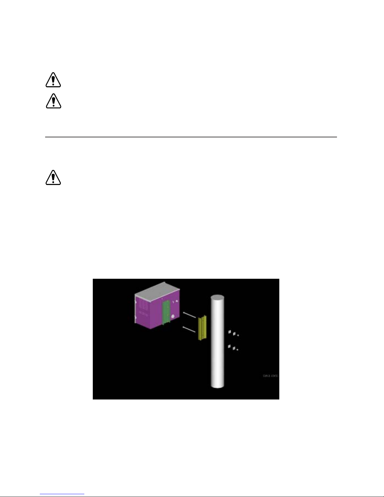
Fig. 2-1, Pole Mount Installation
745-573-B0-001 REV. A
Page 17

2.0 Cabinet Installation, continued
2.1 Pole Mounting, continued
2. Remove the U-shaped bracket from the cabinet rear panel.
3. Use the bracket as a template to mark mounting holes at the desired mounting location. If possible,
position the cabinet so that the front panel and the external LED’s are easily visible.
NOTE: If attaching to a concrete pole additional mounting hardware will be required for the
installation. Lectro does not provide the metal bands required to mount to a
concrete pole. This hardware can be obtained from a cable TV hardware supplier.
4. Drill 11/16" (17.5mm) holes in the pole at the marked locations.
5. Attach the bracket to the pole using 5/8" (M16-2.0) hardware (not provided). Make sure that the head
of the bolt is next to the pole bracket and the nut is at the rear of the pole. Tighten securely.
6. Raise the cabinet and set into place on the bracket already attached to the pole. The slots on the pole
bracket should be pointing downward so that the cabinet will slide onto the bolts on the polemounting bracket. Attach the cabinet using the hardware provided. Tighten ALL the bolts securely.
7. Confirm the availability of a suitable ground rod at the base of the pole. If required, drive a rod
according to local codes.
8. Refer to Section 2.4 for Electrical Connections.
745-573-B0-001 REV. A
17
Page 18

2.0 Cabinet Installation, continued
2.2 Ground Mounting
Although ground mounting the CPR cabinet can be accomplished by several methods, the following
procedure is recommended:
INST ALLATION PROCEDURE
1. Select an appropriate site. Check with other local utilities for buried plant before site location is
finalized. Remove the turf and level an area of approximately 4" greater than the footprint of the
CPRTM cabinet. Refer to Figure 2-2 for details.
2. In accordance with local codes, install the disconnect box near the AC power source.
NOTE: The disconnect box should have a high magnetic type circuit breaker, capable of
passing short duration inrush currents, and have a minimum rating as shown below.
● For 120 VAC 60 Hz units, the service disconnect shall be a high-magnetic type circuit breaker
rated for 20 amperes in the line lead only.
● For 240 VAC 60 Hz units, the service disconnect shall be a 2 pole, high-magnetic type circuit breaker
rated for 15 amperes.
● For 230 VAC 50 Hz units and 220 VAC 60 Hz units, the service disconnect shall be a high-magnetic
type (motor rated type 3 or 4) circuit breaker rated for 16 amperes in the line lead only.
3. From the disconnect box, install conduit to the power supply site and turn a stub up to extend above
grade level. Drive a suitable ground rod according to local codes.
4. Install appropriate size conduit for the output connections and turn a stub up to extend 1" above the
pad surface cast into the concrete. Make sure to match conduit locations with the appropriate cabinet
locations; these locations are indicated in Figure 2-2.
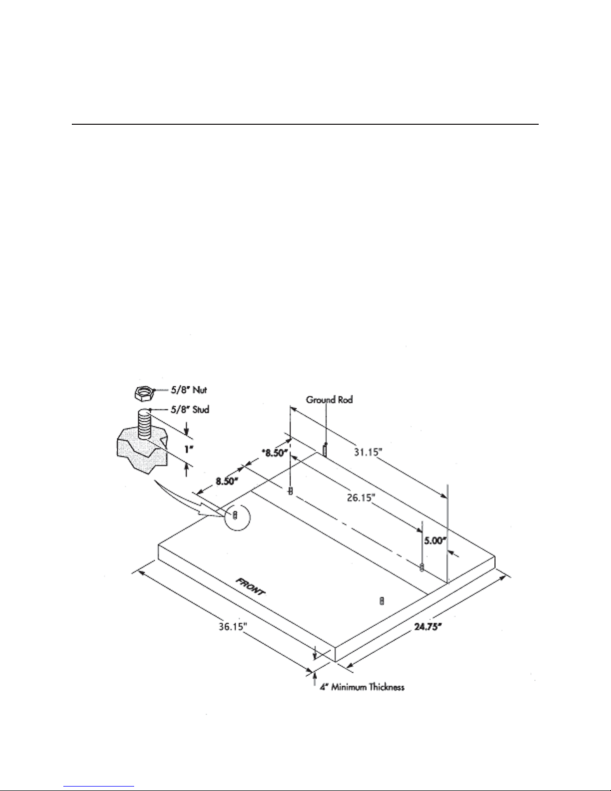
5. Using appropriately sized lumber, construct a form for the cement pad (refer to Figure 2-2 for
dimensions). Anchor the form securely to the ground. If a pre-formed pad is utilized for the mounting
of the CPR cabinet, check the bolt patterns for proper alignment before anchoring the pad to the
ground.
6. Attach the ground mounting brackets from the supplied hardware to the ground skirt using the
5/16”-18 X 3/4” screws and 5/16”-18 nuts. Tighten securely.
7. Make a template from sheet metal or wood indicating the position of the ground-mounting bracket
mounting holes.
18
745-573-B0-001 REV. A
Page 19
2.0 Cabinet Installation, continued
2.2 Ground Mounting, continued
INST ALLATION PROCEDURE, CONTINUED
8. Drill out the two holes in the template and insert two 5/8" X 4" (M16-2.0 x 100mm) bolts (not
supplied). The heads of the bolts will be embedded into the concrete pad when installation is
complete. Leave sufficient thread above the pad for securing the ground skirt.
9. Center the template (with holes in position) over the form. Be sure the conduit stub-ups for the AC
input, ground rod, and AC output are positioned at the desired locations just outside the ground skirt.
Optional: The conduit stub-ups may pass through the cement pad as shown below.
10. Pour, level, and finish concrete to the bottom of the template. Allow a curing time of 24 hours.
11. Attach ground skirt to power supply cabinet. Align skirt inside bottom lip of the cabinet and secure
using 10-32 X 3/8" screws from the parts kit.
12. Attach the power supply cabinet to the concrete pad using 5/8" (M16-2.0) nuts (not provided) through
the ground mounting brackets. Tighten all hardware securely.
745-573-B0-001 REV. A
Fig. 2-2, Pad Dimensions
19
Page 20
2.0 Cabinet Installation, continued
2.3 Enclosure Grounding
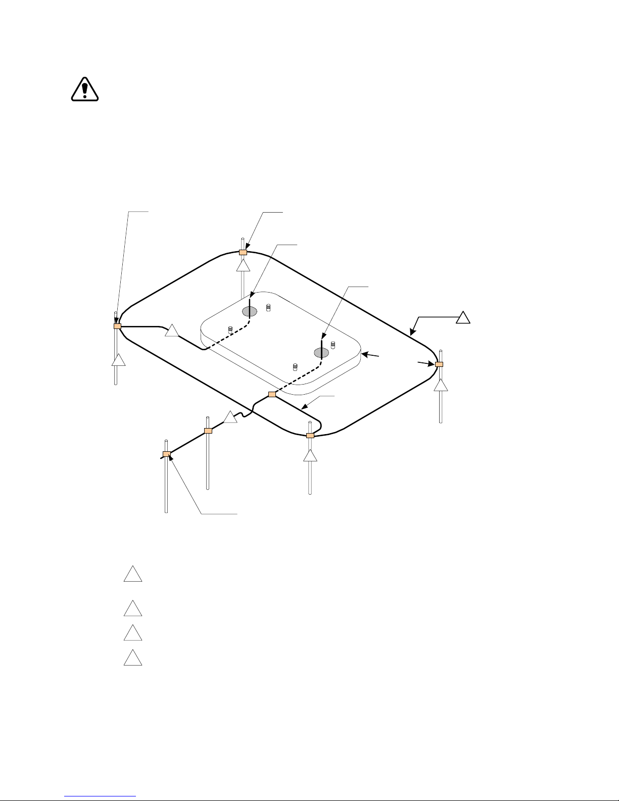
NOTE: Alpha Technologies recommends using the grounding method illustrated below. The grounding
method for a particular site will be dependant upon soil type, available space, local codes, NEC
(National Electric Code), and other site-specific characteristics. Alpha Technologies recommends
5 ohms minimum ground resistance between enclosure and ground rods, in accordance with
IEEE 1100-1999 “Powering and grounding Electronic Equipment”.
Alpha Technologies assumes no responsibility orliability for failure of the installer to
comply with the requirements of all applicable local and national codes. Where allowed,
exothermic welding may be used as an alternative to Burndy clamps and connectors.
Burndy YGHP58C2W-3
or Equivalent
Burndy YGHP58C2W-2TN
or Equivalent
Terminate at
Enclosure Ground Bar
2
Terminate at
Service Entrance Ground
3
4
2
'
m
i
n
2
.
2
#2 AWG
1
2
Fig. 2-3, Enclosure Grounding
Service Grounding (required)
#6 bare copper wire from Service Neutral/Ground Bar with 2 ground rods located 6' apart.
1
Lightning Protection (optional)
2
1/2" x 8' Copper ground rod, four places driven about 2 feet (typical) from the corners of the pad.
#6 bare Copper wire loop terminated to each ground rod and buried below grade (30 inches, min.
3
Corrosion-proof connections (25+ year life-span) and hardware suitable for direct burial MUST be used.
#6 bare Copper wire from loop to enclosure.
4
20
Two 8' Ground Rods 6' Apart (min)
745-573-B0-001 REV. A
Page 21

2.0 Cabinet Installation, continued
2.4 Electrical Connections
WARNING: Be sure the utility (mains) disconnect is off and that no conductors are energized
before proceeding.
CONNECTION PROCEDURE
1. Open the cabinet doors.
2. Install liquid tight conduit to the fitting on the cabinet rear panel and pull the AC primary into the
cabinet housing.
3. Using the receptacle (if provided), connect the AC high input (black) to the copper receptacle
terminal, the AC neutral (white) to the silver receptacle terminal, and the utility protective ground
(green) to the green receptacle terminal. Tighten the screw to a torque setting of 20 lb-in.
4. Position all wiring neatly in the receptacle box. Install the receptacle and then the receptacle cover.
NOTE: Some cabinets do not have receptacles. In this case, the appropriate receptacle
may be supplied by the installer.
5. Using the output wire harness (green and yellow wires with “snap-in” connectors, a seizure clamp,
and O-ring) and cable “feed through” adapter from the parts kit, install the cable adapter and ground
wire. Insert the cable adapter from outside the cabinet into the paint-masked hole. The adapter may
be mounted on the back of the cabinet, (Figure 1-3), or in one of the holes in the bottom battery
shelf (typical for ground mounting, see Figure 1-5). Use the lock nut to secure the adapter and the
large O-ring to the cabinet. Tighten securely. Repeat this procedure for units with dual outputs (24
amp model).
6. Install your choice of coax cable in the adapter. A 90° adapter may be required for some
installations. Connect the yellow output wire to the center pin of the cable by sliding the seizure
clamp into place and tightening securely. Cut the center pin of the cable to allow about 1/4" of the
pin to extend beyond the end of the clamp. Slide the protective boot over the connector center pin
and seizure clamp.
7. Connect an unbroken #6 AWG soft-drawn copper ground wire between the ground lug provided on
the back of the cabinet and the ground rod for transient voltage protection. Note: Keep the ground
wire as straight as possible. Use a ground rod clamp of the proper type, above or below grade.
8. Proceed with the CPRTM Power Module installation as described in Section 3.
745-573-B0-001 REV. A
21
Page 22
3.0 Power Supply, continued
3.1 CPRTM Module Installation and Connection
NOTE: The CPR module weighs 56 lbs/25 kg. (65 lbs./30 kg for the 24 ampmodel), and the
center of gravity is offset to the right. The unit may be lifted using both of the lifting
handles on the front of the module.
CAUTION: When pulling the unit forward from a shelf, be sure to support the right hand
rear corner.
INST ALLATION PROCEDURE
1. Verify the battery breaker on the front panel of the CPRTM is open (off).
2. Connect the green and yellow output harness on the CPRTM UPS to the mating connector on the
harness that is installed in the cabinet. Verify the connector colors match.
(Green is electrically tied to chassis ground-electrically the same as white in Alpha enclosures)
3. Connect the green ground wire from the CPR
TM
UPS to the back of the mounting bolt that holds
the exterior ground clamp to the wall of the enclosure. Use the #10 hardware provided.
4. For those power supplies with IEC power cords, plug the cord into the receptacle on the left side of
the power supply. Use only an HAR-approved power cord for 50 Hz installations. Tighten the
screw on the clamp until the power cord is secure (if clamp is installed).
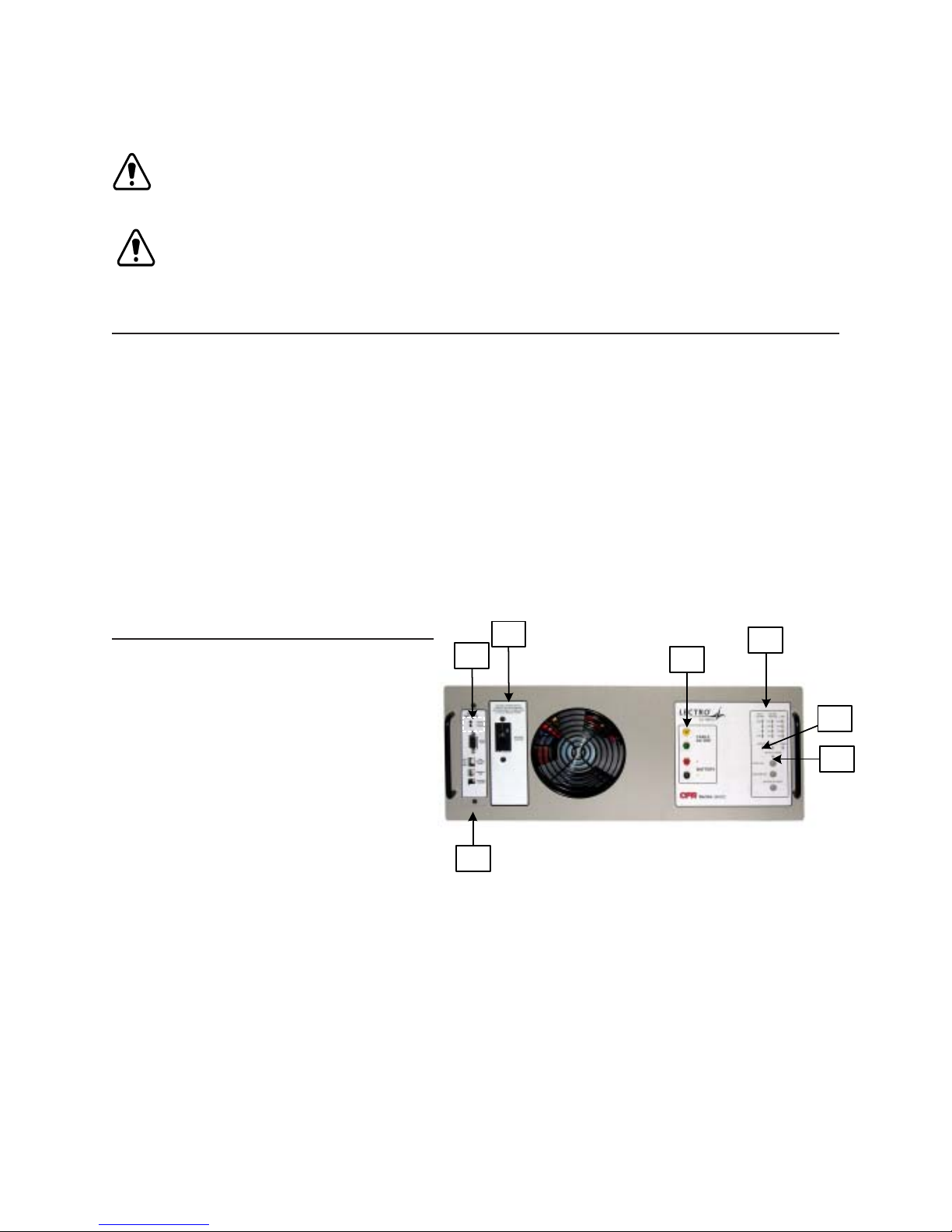
FRONT PANEL LAYOUT, ALL UNITS
A."WEAK BATTERY" LEDS
. CPR COMMUNICATOR MODULE
B
. BATTERY BREAKER
C
. TEST POINTS
D
. LED DISPLAY
E
. INVERTER "ON" DISPLAY
F
. OUTPUT "ON" LED
G
C
A
B
D
E
Fig. 3-1 Front panel layout (all models)
F
G
22
745-573-B0-001 REV. A
Page 23

3.0 Power Supply,
3.1 CPRTM Module Installation and Connection, continued
5. If the batteries are not installed, install them at this time per the instructions in Section 3.2. Connect
the battery sensing wire harness to the appropriate battery terminals as shown in Figure 3-7 or
3-8. Use appropriate flat washers when connecting this harness to small battery terminals. Plug
the connector from the battery sensing harness into the mating connector on the CPR
Communicator Module at the front of the power supply module.
6. Locate the wire harness that connects to the LEDs on the exterior of the CPR outdoor enclosure.
Plug this harness into the mating connector on the CPRTM Communicator Module at the front of
the power supply module.
7. If a Tamper Switch is installed in the cabinet, plug it’s wire harness into the mating connector on
the CPRTM Communicator Module at the front of the power supply module.
8. If the optional Battery T emperature Probe is used, connect the sensor plate cont aining the small
PC board to the most negative battery terminal (the same terminal where the negative [black] wire
from the CPRTM module is connected, see Fig. 3-9 to 3-1 1). Plug in the modular phone type connector
into the RJ-11 port on the left side of the CPRTM module.
continued
TM
9. Confirm that the battery breaker on the front of the CPRTM module is open (off). Connect the ring
lugs at the other end of this harness to the positive and negative terminals of the battery as described
in Section 3.2. Use appropriate flat washers when connecting this harness to smaller battery
terminals. Plug the large gray battery power plug into the receptacle on the left side of the CPR
module (red and black connectors for 36 VDC units).
10. Select the appropriate output voltage for the network that this UPS is powering. This is accomplished
by plugging in the short yellow wire(s) on the left side of the CPRTM module into the receptacle
labeled “48 V ,” “60 V,” 75 V,” or “87 V .” This setting determines the voltage that will be present at the
green and yellow connector on the output harness (or the coaxial fitting) when the CPR unit is
operating.
CAUTION: If the unit is set for 75 or 87 VAC, verify the network components (actives and
passives) are rated to handle these higher voltages before energizing the CPR
power supply.
11. Confirm that the external AC disconnect is OFF.
12. Plug the AC input cord into the receptacle at the left rear of the outdoor enclosure.
The CPRTM system is now ready to be energized. Follow the operating procedure in Section 3.3
TM
TM
745-573-B0-001 REV. A
23
Page 24
3.0 Power Supply, continued
3.1 CPRTM Module Installation and Connection, continued
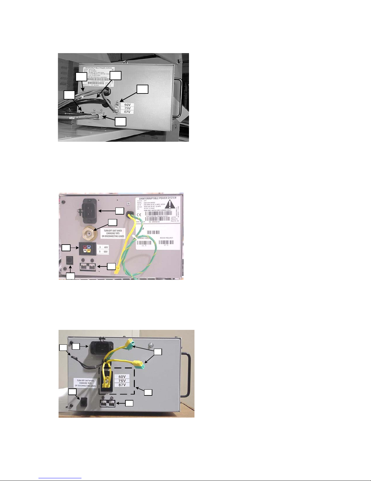
A
E
Fig. 3-2, Connection points for 60Hz, 15A units
D
C
A. AC output cable
B. Output voltage select
C. Battery power cable (Fig. 3-5, 3-6)
D. AC input
B
E. Temp. probe connector
D
A
B
C
E
Fig. 3-3, Connection points for 50Hz Euro units
D
F
A
A
A. AC output fitting
(Note: Green w/yellow trace and solid
yellow cables may also be used for output
connection.)
B. Output voltage select
C. Battery power cable connection
D. AC input
E. Temp. probe connector
A. AC output cables
B. Output voltage select
C. Battery power cable
D. AC input
E. Temp. probe connector
F. Generator Interface (Mini-Node)
E
Fig. 3-4, Connection points for 60Hz, 24A units
24
B
C
745-573-B0-001 REV. A
Page 25

3.2 Battery Installation and Connection
CAUTION: Short circuit danger: Do not rest tools or equipment on top of batteries. Do not
allow batteries to become shorted as an explosion may occur causing severe
injury. Do not open or mutilate batteries. Released electrolyte is extremely
harmful to skin and eyes. Do not dispose of batteries in fire as an explosion my
occur.
CAUTION: Government regulations may require that batteries be recycled. See your
battery distributor for details on recycling (third-party batteries) or contact Alpha
Technologies for recycling AlphaCellTM battery products.
CAUTION: Batteries shall be 12 Vdc with the same amp-hour rating. Do not mix old and
new batteries; replace batteries as a set using UL recognized batteries.
CAUTION: Servicing of batteries shall be performed or supervised by personnel
knowledgeable of batteries and the required precautions. Keep unauthorized
personnel away from batteries.
3.0 Power Supply,
continued
CAUTION: The following precautions shall be observed when working with batteries:
• Follow approved OSHA (or appropriate other) regulations for handling batteries.
• Always wear eye protection and a protective vest when working near batteries.
• Batteries produce explosive gases. Keep away all sparks and flames.
• Remove watches, rings or other metal objects
• Use tools with insulated handles.
• Wear rubber gloves and boots
Tools required: 10mm (Lectro™) or 7/16” (AlphaCell™) socket
Inch-pound torque wrench
Multimeter
745-573-B0-001 REV. A
25
Page 26
3.0 Power Supply, continued
3.2 Battery Installation and Connection, continued
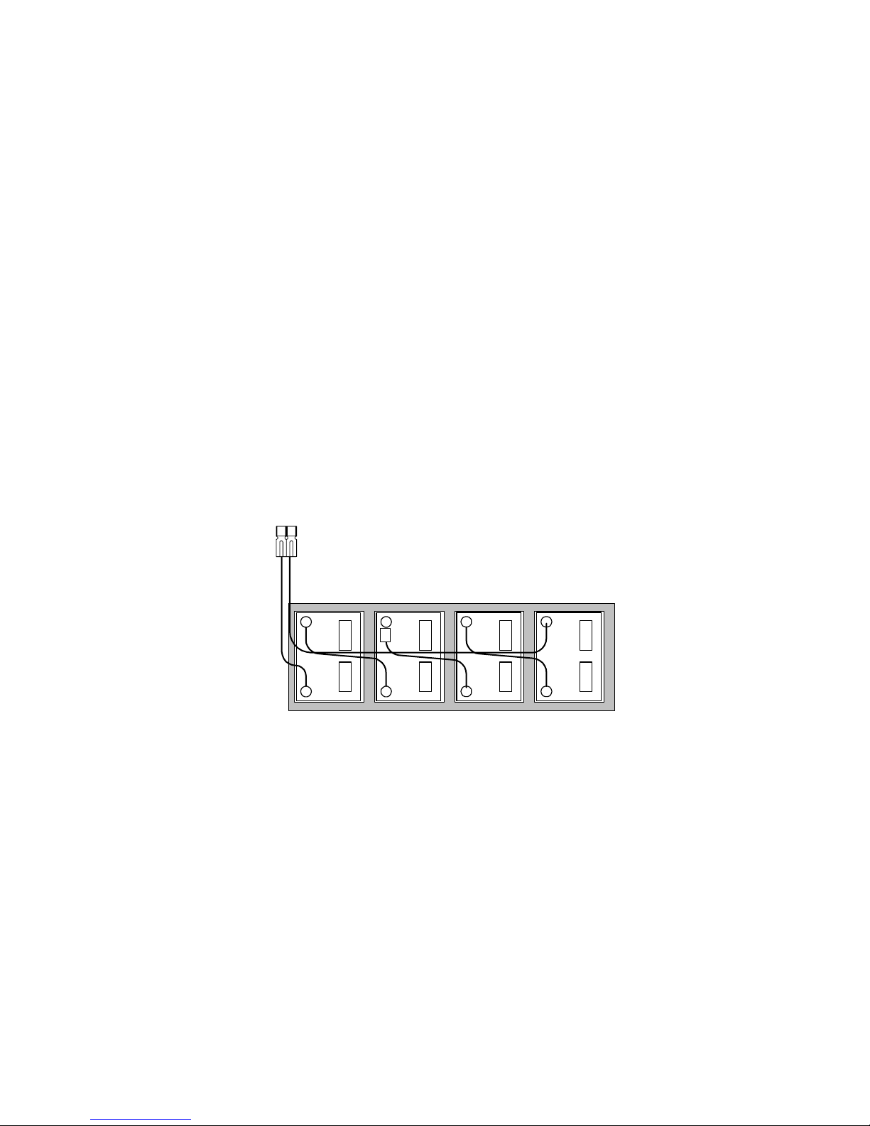
3.2.1 48V Battery Installation Procedure
1. Confirm the CPRTM DC circuit breaker is off (down).
2. Place the batteries in the bottom of the cabinet, negative terminals (-) at the rear of the cabinet.
3. Connect the red battery cable which comes from the gray connector on the CPRTM module to the
positive (+) terminal of the left battery. Torque all connections to 60 inch-pounds (6.8 Newtonmeters).
4. Connect the three (3) battery interconnection jumpers as shown below. Torque all
connections to 60 inch-pounds (6.8 Newton-meters).
5. Confirm that the CPR
TM
DC circuit breaker is off (down). Connect the black battery cable which
comes from the gray connector on the CPRTM module to the negative (-) terminal of the right
battery. Torque connection to 60 inch-pounds (6.8 Newton-meters).
6. Measure the DC voltage to ensure proper installation of all battery wiring. Open circuit DC voltage
should measure between 45 volts and 51 volts.
7. Verify that the gray Anderson connector is properly attached to the left side of the CPRTM module.
Gray Anderson
Connector
BLACK
-
+
RED
-
Fuse
+
CABINET FRONT
-
+
-
+
Fig. 3-5, 48V Battery Connections – single string P/N 875-182-21
26
745-573-B0-001 REV. A
Page 27

3.0 Power Supply,
3.2 battery Installation and Connection, continued
3.2.2 36V Battery Installation Procedure
1. Confirm the CPRTM DC circuit breaker is off (down).
2. Place the batteries in the bottom of the cabinet, negative terminals (-) at the rear of the cabinet.
continued
3. Connect the red battery cable which comes from the red and black connector on the CPR
TM
module to the positive (+) terminal of the left battery. Torque all connections to 60 inch-pounds
(6.8 Newton-meters).
4. Connect the two (2) battery interconnection jumpers as shown below. Torque all connections to
60 inch-pounds (6.8 Newton-meters).
5. Confirm that the CPR
TM
DC circuit breaker is off (down). Connect the black battery cable which
comes from the red and black connector on the CPRTM module to the negative (-) terminal of the
right battery. Torque connection to 60 inch-pounds (6.8 Newton-meters).
6. Measure the DC voltage to ensure proper installation of all battery wiring. Open circuit DC voltage
should measure between 34 volts and 38.5 volts.
7. Verify that the red and black Anderson connector pair is properly attached to the left side of the
CPRTM module.
Red and Blac k
Anderson
Connector
BLACK
-
-
Fuse
-
Fig. 3-6, 36V Battery Connections – single string P/N 874-202-20
745-573-B0-001 REV. A
+
RED
+
CABINET F R ON T
+
27
Page 28
3.0 Power Supply, continued
3.2 Battery Installation and Connection, continued
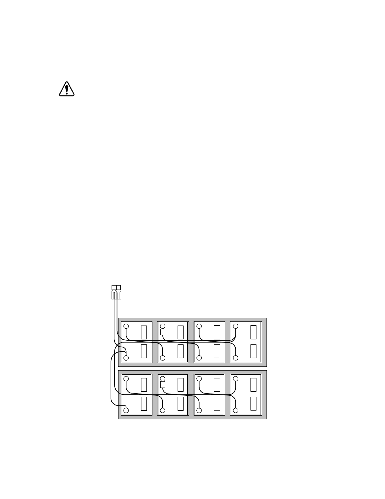
3.2.3 Connecting an Additional 48V Battery String
NOTE: This procedure assumes that the additional battery string is being installed in a
Lectro brand cabinet.
1. Confirm the CPRTM DC circuit breaker is off (down).
2. Place the batteries in the bottom of the cabinet with the negative terminals (-) at the rear of the
cabinet.
3. Connect the red battery lead from the lower shelf at the positive (+) terminal of the left battery.
Torque connection to 60 inch-pounds (6.8 Newton-meters).
4. Disconnect the red battery lead cable from the upper shelf at the positive (+) terminal of the left
battery. Reconnect this lead with the red lead of the inter-shelf connection cable.
5. Connect the three (3) battery interconnection jumpers as shown below. Torque all
connections to 60 inch-pounds (6.8 Newton-meters).
6. Disconnect the black battery lead cable from the upper shelf at the negative (-) terminal of the
right battery. Reconnect this lead with the black lead of the inter-shelf connection cable. Torque
connection to 60 inch-pounds (6.8 Newton-meters).
7. Measure the DC voltage to ensure proper installation of all battery wiring. Open circuit DC voltage
should measure at least 48 volts across both parallel strings.
8. Verify the gray Anderson connector is properly attached to the left side of the CPR module.
Gray Anderson
Connector
BLACK
-
+
-
RED
-
Fuse
+
-
Fuse
-
+
-
-
UPPER
SHELF
+
-
LOWER
SHELF
+
Fig. 3-7, 48V Battery Connections – parallel strings P/N 875-183-20
28
+
CABINET FRONT
+
+
745-573-B0-001 REV. A
Page 29
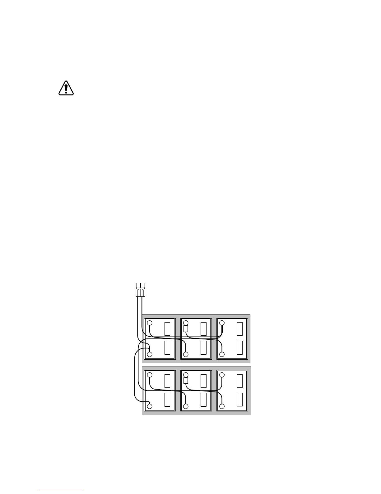
3.0 Power Supply,
3.2 Battery Installation and Connection, continued
3.2.4 Connecting an Additional 36V Battery String
NOTE: This procedure assumes that the additional battery string is being installed in a
Lectro brand cabinet.
1. Confirm the CPRTM DC circuit breaker is off (down).
2. Place the batteries in the bottom of the cabinet with the negative terminals (-) at the rear of the
cabinet.
3. Connect the red battery lead from the lower shelf at the positive (+) terminal of the left battery.
Torque connection to 60 inch-pounds (6.8 Newton-meters).
4. Disconnect the red battery lead cable from the upper shelf at the positive (+) terminal of the left
battery. Reconnect this lead with the red lead of the inter-shelf connection cable.
5. Connect the two (2) battery interconnection jumpers as shown below. Torque all connections to
60 inch-pounds (6.8 Newton-meters).
continued
6. Disconnect the black battery lead cable from the upper shelf at the negative (-) terminal of the
right battery. Reconnect this lead with the black lead of the inter-shelf connection cable. Torque
connection to 60 inch-pounds (6.8 Newton-meters).
7. Measure the DC voltage to ensure proper installation of all battery wiring. Open circuit DC voltage
should measure at least 36 volts across both parallel strings.
8. Verify the red and black Anderson connector pair is properly attached to the left side of the CPR
module.
Red and Black
Anderson Connector
BLACK
-
+
-
RED
-
Fuse
+
-
Fuse
-
UPPER
SHELF
+
-
LOWER
SHELF
Fig. 3-8, 36V Battery Connections – parallel strings P/N 870-132-23
745-573-B0-001 REV. A
+
+
CABINET FRONT
+
29
Page 30
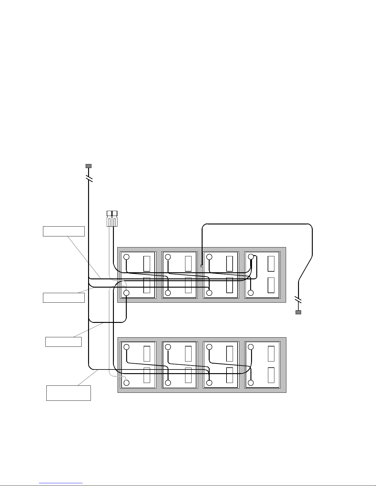
3.0 Power Supply, continued
3.2 Battery Installation and Connection, continued
3.2.5 Battery Removal
1. Turn the DC circuit breaker off (down) and observe all precautions for the safe handling
of batteries as previously outlined.
2. Remove all batteries in the reverse order of installation.
BATTERY SENSE INPUT
For Level 3 wiring, refer to manual P/N 040-0080-1501
Negative (Black)
Middle (Orange)
Positive (Red)
Middle, Longer
lead (Orange)
RED
Gray Anderson
Connector
BLACK
UPPER SHELF
-
+ +
-
+
- -
+
LOWER SHELF
-
+
CABINET FRONT
OPTIONA L XM STYLE
TEMPERATURE PROBE
-
+
TEMP PROBE INPUT
-
+
-
+
Fig. 3-9, 48V Battery Sensing and Temperature Probe Connection – Parallel Strings
30
745-573-B0-001 REV. A
Page 31
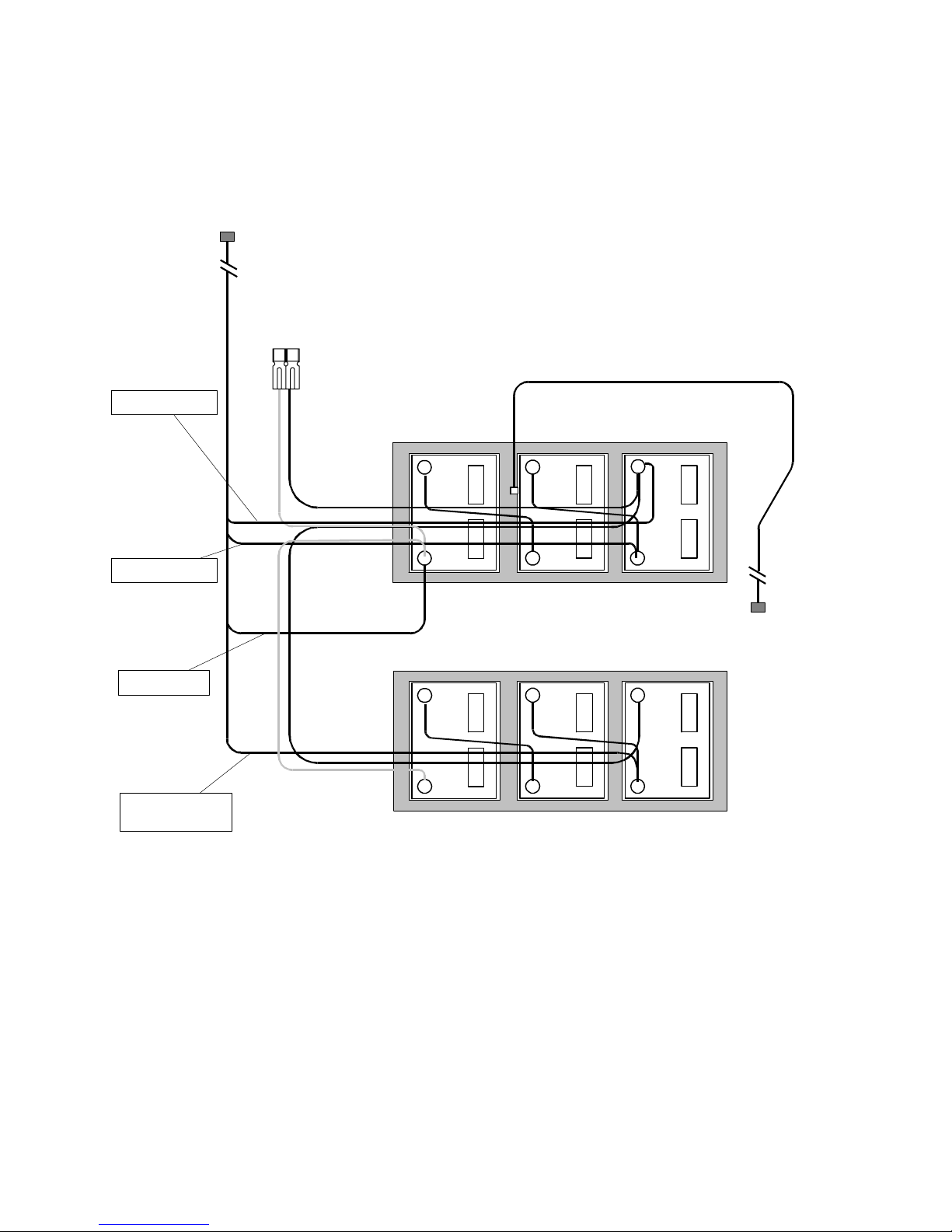
3.2 Battery Installation and Connection, continued
BATTERY SENSE INPUT
For Level 3 wiring, refer to manual P/N 040-0080-1501
3.0 Power Supply,
continued
Negative (Black)
Middle (Orange)
Positive (Red)
Middle, Longer
lead (Orange)
RED
Red and Black
Anderson
Connector
BLACK
OPTIONA L XM STYLE
TEMPERATURE PROBE
UPPER SHELF
-
+
-
+
-
+
LOWER SHELF
-
+
-
+
TEMP PROBE INPUT
-
+
CABINET FRO NT
Fig. 3-10, 36V Battery Sensing and Temperature Probe Connection – Parallel Strings
745-573-B0-001 REV. A
31
Page 32
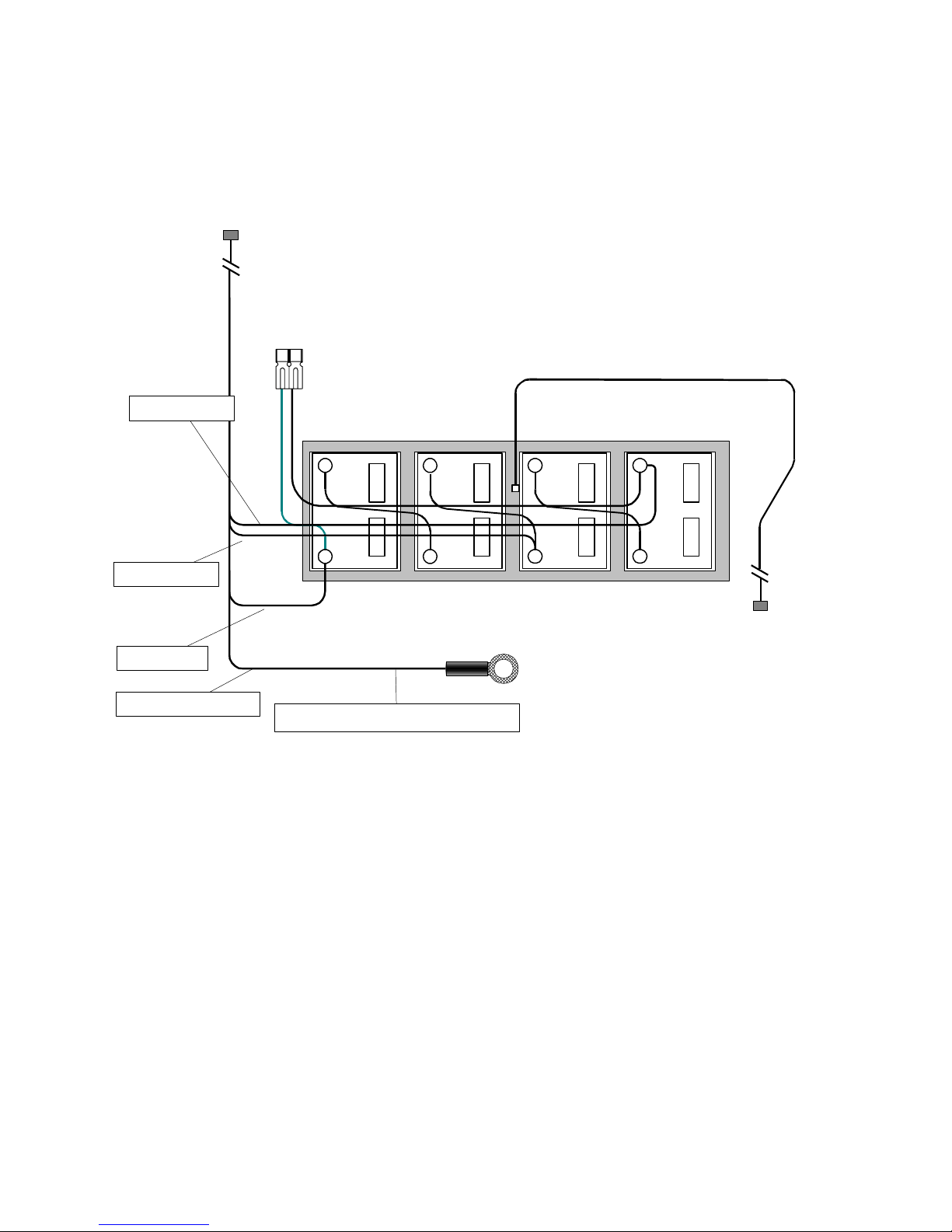
3.0 Power Supply, continued
3.2 Battery Installation and Connection, continued
BATTERY INPUT
For Level 3 wiring, refer to manual P/N 040-0080-1501
Negative (Black)
Middle (Orange)
Positive (Red)
Middle Longer (Orange)
Gray Anderson
Connector
RED
BLACK
UPPER SHELF
-
+
If unused, tuck connector out of the way
- -
+
CABINET FRO NT
OPTIONA L XM STYLE
TEMPERATURE PROBE
-
+
+
TEMP PROBE INPUT
Fig. 3-11, Battery Sensing and Temperature Probe Connection – Single String
32
745-573-B0-001 REV. A
Page 33
3.3 Operation
TM
CPR
UPS STARTUP AND INVERTER TEST PROCEDURE:
3.0 Power Supply,
continued
1. Verify that all connections to the CPR
TM
have been made correctly as described in Section 3.1.
2. Verify that the desired output voltage has been selected (48V, 60V, 75V, or 87V) via the
connection at the left side of the CPRTM module. Check to see that the AC input cord and Battery
power cables are plugged in.
3. Turn on the external disconnect breaker (supplied by the installer), then close the battery
breaker on the front of the CPRTM module. There should be only green LEDs lit on the display. If
red LEDs are illuminated, see Section 4, Troubleshooting.
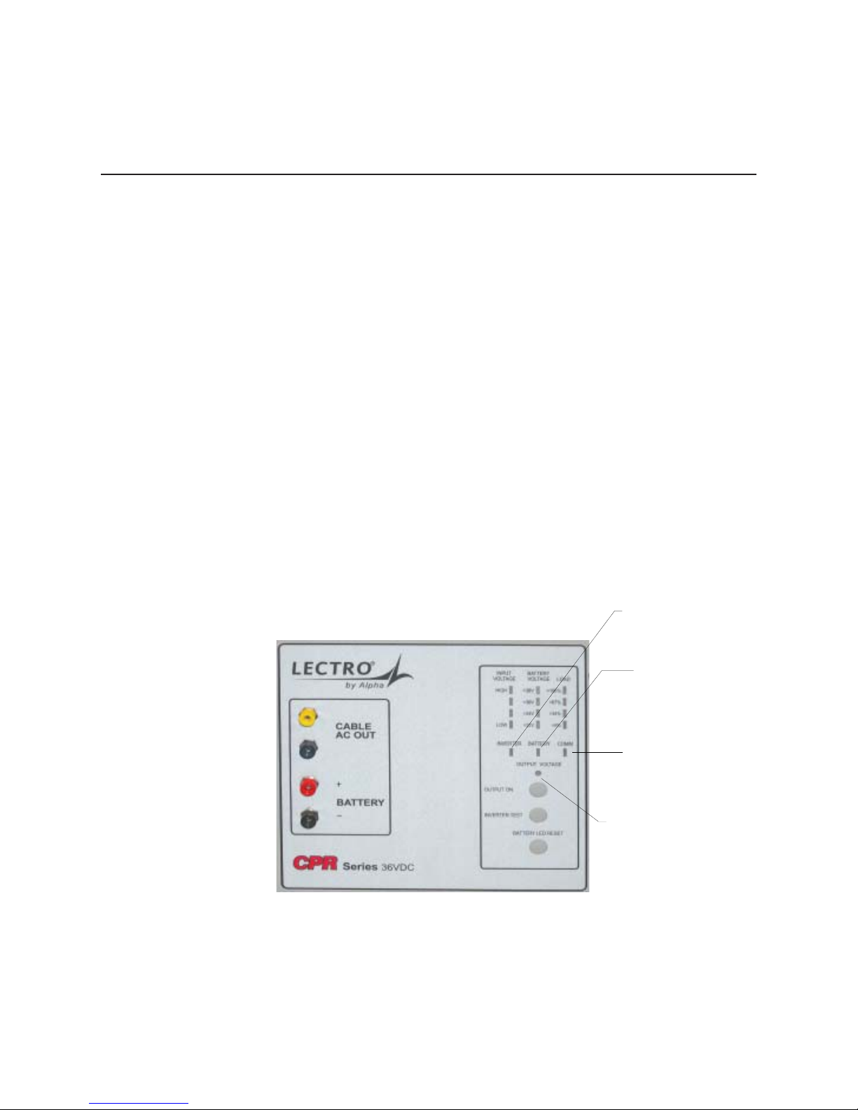
4. Verify that the “Output Voltage” green LED is lit on the front display. The CPRTM System should
now be providing power to your network. Verify with a voltmeter at the point where the coax exits
the cabinet.
5. The front panel display includes “bar graph” indicators to describe input voltage levels, battery
voltage levels, and output load levels.
6. Check the front panel test points with a true RMS voltmeter. CABLE AC OUT should read within
±3-5% (maximum range is tap-dependant) of the configured output voltage (48, 60, 75, 87V).
BATTERY should read between 45 and 56Vdc (34V and 42V for 36V units), depending upon the
age, temperature, and state-of-charge of the batteries.
Fig. 3-12, Front Panel Display
INVERTER ON
(RED FLASHING)
WEAK BATTERY
SOLID
RED
UPS COMMUNICATING
= HANDSHAKE
SOLID
FLASHING
OUTPUT VOLTAGE
(GREEN)
LED
= DATA
745-573-B0-001 REV. A
33
Page 34

3.0 Power Supply, continued
3.3 Operation, continued
7. Verify the external LEDs on the CPRTM outdoor cabinet are functioning. In normal operation,
the green external LED will be ON solid, (not flashing). The green LED flashes when the CPR
TM
system is on battery, and the red LED flashes when there is a system alarm or failure.
8. INVERTER TEST: This test will verify proper operation of the system inverter. Push the front
panel button labeled “Inverter Test.” The red “inverter” LED should flash on the front panel, and
the fan will run. Check the CABLE AC OUT test points for proper voltage. The inverter test lasts
from 1.0 to 2.0 minutes, and will automatically return to normal mode at the conclusion of the
test. If the inverter fails to start, check for an open battery breaker or a loose battery terminal
connection.
9. GENERATOR MODE: To allow AC operation from a generator, the CPR provides a ‘relaxed’ AC
input criteria mode. To set generator mode press the OUTPUT ON and INVERTER TEST
buttons simultaneously. To return to normal mode, press the OUTPUT ON and INVERTER TEST
buttons again. After 48 hours in generator mode, the CPR will put itself back into normal mode.
10. Once the unit has returned to normal operation, after the inverter test, the system startup is
complete.
NOTE: The CPRTM UPS can also be “hot started” on battery power when utility power is not
present. To hot start the CPR, close the battery breaker on the front panel, and
press and hold the “output on” button. The inverter will start within 3 seconds. The
unit will operate until the battery capacity is depleted.
CPR SHUTDOWN PRECEDURE:
To shut down the CPRTM power supply, open the battery breaker, and unplug the AC power cord.
WARNING: RISK OF ELECTRIC SHOCK. Hazardous electrical live parts inside the power
supply are energized from the batteries even when the input AC power is
disconnected.
34
745-573-B0-001 REV. A
Page 35

3.0 Power Supply,
3.4 Maintenance
3.4.1 Routine Maintenance Checks
NOTE: It is important that secure mechanical and electrical connections be maintained on
this equipment. Secure connections will help prevent outages and equipment
damage. Refer to the following page for a sample of a maintenance log sheet.
1. Inspect the external ground connections for mechanical integrity and good physical condition.
Check the cabinet for damage and check the mounting hardware for mechanical integrity.
2. Open the cabinet. Check tightness of all battery, internal ground, and output connections.
Observe condition of batteries. If the cabinet shows signs of excessive dust or moisture, check
for lost vent screens. Repair as required, and note any unusual conditions for future reference.
3. Inspect the input surge suppressor (if installed) for obvious damage. If it appears intact, check
its operation with a megger or a similar device to ensure that it is functioning. Note that a failed
surge suppressor may appear visually to be OK, yet allow damaging transients and surges to
enter the power supply, and possibly the coax network. It is very important to test the surge
suppressor with a megger to make sure it is
actually protecting the power supply.
continued
4. On the maintenance log sheet, mark which LEDs are illuminated on the front panel of the CPR
UPS. The presence of any red LED indicates an alarm or failure which will require immediate
attention. See Section 4.1 for troubleshooting information.
5. The CPRTM system will automatically and periodically load test the batteries. If a failing battery is
detected, the battery LED (red) on the front panel will illuminate. If the battery LED is
illuminated, replace the affected battery (or string of batteries) and press the “battery LED reset”
button on the front panel. See Section 3.2.1 for the battery removal procedure.
6. Use a true RMS meter to record AC output voltage and battery voltage at the front panel test
points. If available, use a clamp-on current probe to record AC output current at the cable
adapter.
7. Turn the battery circuit breaker off (down). Record the voltage for each battery (well matched
batteries should differ by no more than 0.2 Vdc). If the battery has a date code on the label,
record it on the maintenance log sheet.
8. Using a battery load tester, check the performance of each battery. Note that the CPR UPS
performs battery load testing automatically, so this step may be omitted if desired.
9. Close the battery circuit breaker on the front panel.
10. Force the unit into standby operation by pressing the “inverter test” button on the front panel.
Verify that the red inverter LED illuminates and that the output voltage remains within +/- 3-5%
of the nominal voltage (48, 60, 75 or 87 VAC). Verify the unit returns automatically to normal
operation after 1 to 2 minutes.
TM
11. Confirm that only GREEN LEDs are illuminated, remove all tools and meters, and close and lock
the cabinet. This completes routine maintenance of the CPRTM power supply.
745-573-B0-001 REV. A
35
Page 36

3.0 Power Supply, continued
3.4 Maintenance, continued
3.4.2 CPR Power Supply Maintenance Log Sheet
Use this form in conjunction with the maintenance procedures in the previous
section.
Cable Company:___________________________________________________
Inspection Date:________________ Location:_________________________
Technician:____________________ Model/Serial#:____________________
Visual Problem and Fix:__________________________________
Inspection Comments:_______________________________________
Battery Weak LEDs: String 1: ON / OFF String 2: ON / OFF
LED Display: Mark the illuminated LEDs on the diagram below:
Input Battery Load
BatteryInverter Comm
Output ON
DVM (RMS Voltmeter) Readings
Cable Output Voltage:________ Battery Voltage:________ AC Amps:________
Test Points Test Points Clamp on Probe
Press “Inverter Test” button.
Standby AC voltage:_______ Fan Running? YN
Remove Dust and Moisture fromCabinet:______OK
Comments:_______________________________________________________
________________________________________________________________
________________________________________________________________
________________________________________________________________
36
Fig. 3-13, Maintenance Log Sheet
745-573-B0-001 REV. A
Page 37

3.4 Maintenance, continued
3.4.3 Battery Storage
Always make sure a battery is fully charged before placing it into storage.
Never charge batteries in a gas-tight container.
Always store batteries in a cool, dry location. Optimum temperature is 25°C (77°F).
Always monitor battery, open-circuit voltage at least once every 12 months. If not using a
Lectro CPRTM battery, refer to the manufacturer’s guidelines for storage.
Always provide a refreshing charge if the open circuit voltage drops below 12.2 volts.
3.4.4 Proper Usage
Always make sure a battery is fully charged prior to placing it into service.
Never mix batteries that are at different states of charge. (Refer to battery date codes)
Make sure that the open circuit voltage for each battery in a string is greater than 12.8
volts.
Never mix battery types or batteries that are at different states of charge.
A different state of charge condition likely exists if the open circuit voltage for any battery in
a string deviates from its neighbor by more than ± 0.25 volts.
3.0 Power Supply,
continued
Never leave a battery in a discharged state for any length of time.
3.4.5 Periodic Maintenance
Never forget to periodically check batteries for proper terminal attachment torque every 12
months.
745-573-B0-001 REV. A
37
Page 38

4.0 Troubleshooting, Continued
4.1 Troubleshooting Guide Part 1
Because it is impossible to account for every possible symptom and solution in a CATV Network, the
following troubleshooting suggestions should be used as a general guideline.
ACTIONPROBABLE CAUSESYMPTOM
No AC output to coa x
cable
Inverter does not run, or
module does not transfer
to "standby" either during
a power failure or an
"inverter test".
Utility failure Notify local Power Co..
External input breaker open or tripped Re-close breaker. Verify breaker is
HIGH MAGNETIC type.
AC power cord loose/unplugged Re-insert plug into receptacle
Utility voltage or frequency (or generator
ouput) is out of range. AC input to power
supply must be within the following limits:
Voltage: 96 to 156V (or 19 2V -276V for
240V nominal units, or 161V-299V for
230V nominal units, or 154V-286V for 220
V nominal units ) RMS
Frequency: 57-63Hz
AC output harness is disconnected or
loose.
Inverter failure If the Battery LED is "off" on the front panel,
Battery breaker open Close batter y breaker on front panel.
Measure the AC source voltage and frequenc y.
If out of limits, notify Pow er Co. or, if a
generator is used, either adjust its output, or
select a larger generator.
Verify all connections from the AC output (green
and yellow) connector to the coax fitting.
then the inverter may have failed, and the
TM
module sh ould be replaced
CPR
38
TM
Module fails to
CPR
transfer from "standby"
back to "normal" mode
after a utility outage.
Battery too weak to support inverter. Front
panel "battery" LED should be illuminated.
Utilty (or generator) out of limits on voltage
or frequency. See "No AC output" above.
External input breaker open or tripped. Re-close breaker. Verify breaker is HIGH
Input relay failure Replace CPR
Test batteries with a load tester. Replace any
that fail the test.
Measure the AC source voltage and frequenc y.
If out of limits, notify Power Co., or, if a
generator is used, either adjust its output, or
select a larger generator.
MAGNETIC type.
TM
Module
Table 4-1, Troubleshooting guide, Part 1
745-573-B0-001 REV. A
Page 39

4.2 Troubleshooting Guide Part 2
4.0 Troubleshooting, Continued
ACTIONPROBABLE CAUSESYMPTOM
AC input "High" red LED
is lit.
AC input "Low" red LED is
lit.
Load ">100%" red LED i s
lit.
AC input voltage is above 156 (or 299 for
230V nominal units, or 276 for 240V
nominal units) VAC— unit will be in
standby mode, run ning on battery.
AC input voltage is below 96 (or 161 for
230V nominal units, or 192 for 240V
nominal units) VAC— unit will be in
standby mode, run ning on battery.
CPR unit is l oaded > 100%. I f the overl oad
is >110%, the output will turn off after30
seconds, and then attempt to restart ev er y
30 seconds for 3 hours. If the overload is
not removed after 3 hours, the module will
shut down and must be manually restarted
by pressing the "Outp ut O N" but t on.
Measure the AC input voltage with a tr ue RMS
voltmeter. If above 156V (or 265, or 276),
notify the local power company of the
significant overvoltage at the power supply
locati on Oper at e t he CPR from an alternate
AC source (generator) unt il the overvoltage is
corrected.
Measure the AC input voltage with a true RMS
voltmeter. If below 96V (or 184, or 192), notify
the local power company of the significant
undervoltage at the power supply location
Operate the CP R from an alternat e AC sourc e
(generator) unt il the undervoltage is corrected.
Reduce the ov er load in the coax network.
"Inverter" red LED is lit. Inverter is operating. This is normal if
Utility power has failed.
Output voltage reads zero
or nearly zero at the front
panel test points.
COAX network is shorted. Measure AC output current with a clamp-on
Output has been disabl ed due t o overload
timeout.
Table 4-2, Troubleshooting guide, Part 2
745-573-B0-001 REV. A
Measure AC input voltage wi th a true RMS
voltmeter. If power is present, verify Utility
voltage and frequency is within the limits shown
above in this table.
probe. If it is > rated out put amps, check the
network for a short circuit, or "bucking power"
and correct.
Press "Output ON " but ton. The "Output
Voltage" LED shoul d c ome on. Check
network for overloads.
39
Page 40
5.0 St atus Monitor, Continued
5.1 Installation
The communication module installs in the same basic manner for all three levels of status monitoring.
The external connections will be different as defined in Section 4.3.
1. Turn off the CPR Unit, and remove AC Power.
2. Remove the communication module cover plate (if applicable).
3. Locate and pull out the ribbon cable with the connector, inside of the CPR Communicator
TM
module slot.
4. Plug in the ribbon cable connector into the PC board connector on the CPR Communicator
TM
module.
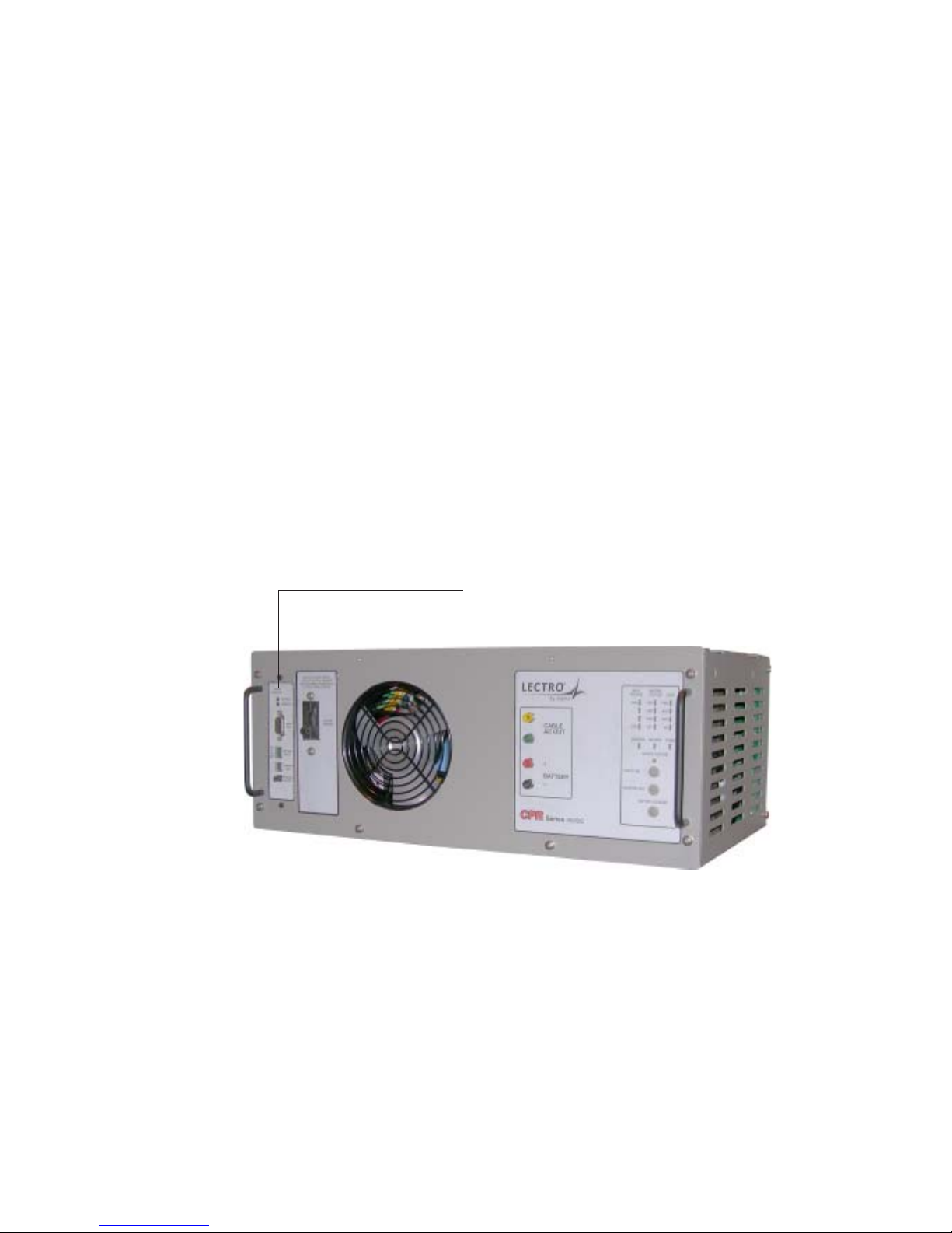
5. Insert the CPR CommunicatorTM module into the open slot on the CPR and secure with the two
mounting screws. Use caution when inserting so as not to “pinch” the ribbon cable between the
slot and the module. Refer to figure 4.1-1.
Communications Module
Fig. 5-1, CPR Unit, Showing Communicator Location
40
745-573-B0-001 REV. A
Page 41
5.0 St atus Monitor, Continued
5.2 Operation
The operation of the status monitor is automatic and carries out its functions without the direct intervention
of the operator. The purpose of the status monitor is to indicate the operating conditions of the CPR power
supply. There are three levels of status monitoring:
LEVEL ONE
Indicates locally (at the power supply) only. This can be a combination of the
external cabinet LED indicators and/or the LED’s on the CPR power supply.
This level is NOT compatible with transponder devices. The information
available in addition to the information displayed on the front of the CPR
power supply is as follows:
• Weak battery string indicators (located on the Communicator module).
• Normal operation, Standby operation and Alarm condition (with the
external cabinet LEDs) The weak battery indicators can be reset by
pushing the Battery LED Reset button, located on the front of the CPR
power supply.
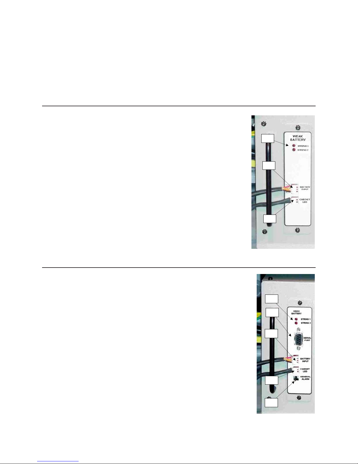
1
2
Level One Commmunicator Module features:
1. Weak Battery Indicator LEDs (one per string).
2. Battery Sensing Harness (connects to battery terminals).
3. Wiring to external cabinet LEDs.
LEVEL TWO
Allows for remote status monitoring with access to additional, more detailed
information. Level Two is essentially the same as Level One with the addition
of a DE-9 connector located on the front of the communication module. The
DE-9 connector is used to indicate remotely via a third party transponder
device. The data available is in RS-232 format. The popular “Palm Pilot” PDA
device may also be connected to this port using a Palm Pilot application and
instructions available from Lectro. A telephony modem may also be connected
to the RS-232 port. Be sure to disable “hardware handshaking” for proper
operation of the modem in this application.
Level Two Commmunicator Module features:
1. Weak Battery Indicator LEDs (one per string).
2. RS-232 DB-9 port for connection between Transponder, Modem, Laptop
PC, or customer-supplied PDA.
3. Battery Sensing Harness (connects to battery terminals).
4. Wiring to external cabinet LEDs.
5. Door Tamper switch connector (shown with shorting jumper).
3
1
2
3
4
5
745-573-B0-001 REV. A
41
Page 42
5.0 St atus Monitor, Continued
5.2 Operation, continued
LEVEL THREE
Allows for remote status monitoring similar to Level One and Two with the DB-9 connector replaced by a
F-81 style, 75-ohm, RF connector. This level is proprietary or HMS, and directly compatible with
CheetahNet. Level Three is used to indicate remotely via an internal (inside the communicator module)
RF transponder for use with CheetahNet. The F-81 connector is used to make the connection between
the transponder and the CATV Network.
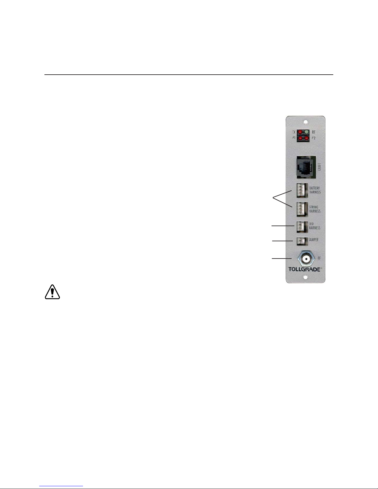
Level Three Commmunicator Module features:
1. Battery Sensing Harness (connects to battery terminals).
2. Wiring to external cabinet LEDs.
3. Door Tamper switch connector (shown with shorting jumper).
4. F81 connector for RF output (direct to COAX).
Level I and II battery sense cables are NOT compatable with the
level III module. Refer to the embedded transponder manual
P/N 040-0080-1501 for detailed instructions and wiring harnesses
NOTE: All three levels have the ability to provide local indications. Each level uses a
different communication module, mounted on the left side of the CPR module.
1
2
3
4
5.3 Maintenance
1. Test the CPR Communicator™ for the correct signals by monitoring the specific CPR module at
the headend.
2. Simulate the “General Alarm” signal by removing the plug (or shorting jumper) on the front of the
CPR module. Verify this alarm is received at the headend.
3. Check all wiring connections.
The CPR Communicator™ Module should be tested and the connections checked on a regular basis. This
should be performed at least once a year. Other than the two simple steps, described above, there is no
routine maintenance required for the CPR Communicator™ module.
42
745-573-B0-001 REV. A
Page 43

6.1 Electrical, Mechanical Specifications
PARAMETER
Nom inal Input Voltage
Input Voltage Range (%)
Input Voltage Range
Nom inal Input Curr. (Rest m ode)
Input Frequency
Output Voltage
Output Regulation, 87V T ap
Output Regulation, 75V T ap
Output Regulation, 60V T ap
Output Regulation, 48V T ap
Rated Output Current
Waveform
S le w R ate
Crest Ratio (Peak:RM S)
EFFICIENCY @ 87Vrms ON-LINE REST MODE
@ 100% load
@ 80% load
@ 60% load
@ 40% load
120V E xtd Range 220V International 240V (24 A)230V International 23 0V Eu ro (C E)
120V 220V 230V 230V 240V
+30% to -20% +30% to -30% +30% to -30% +15% to -20% +15% to -20%
96 V to 156V 154V to 286V 161v to 299V 18 4v to 265V 192V to 276V
13A 7A 7A 6A 11A
60Hz, ± 3Hz 60Hz , ± 3Hz 50Hz , ± 3Hz 50Hz, ± 3Hz 60Hz, ± 3Hz
87/75/60 Vrm s
(F ield S elec table )
± 3% ± 3% ± 3% N/A ± 3%
± 4% ± 4% ± 4% N/A ± 4%
± 4% ± 4% ± 4% ± 3% ± 4%
N/A N/A N/A ± 3% N/A
15A 15A 15A 15A 24A
60Hz, ± 1Hz 60Hz , ± 1Hz 50Hz , ± 1Hz 50Hz, ± 1Hz 60Hz, ± 1HzOutput frequency, Inverter Mode
Quasi Squarewave Quasi Squarewave Quasi Squarewave Quasi Squarewave Quasi Squarewave
< 100 Volts/ms < 100 Volts/m s < 100 V olts/ms < 100 V olts/m s < 100 Volts/ms
1.3:1 1.3:1 1.3:1 1.3:1 1.3:1
91% 91% 91% 91% 91%
90% 91% 91% 90% 91%
89% 89% 89% 88% 89%
85% 85% 84% 85% 85%
87/75/60 Vrm s
(F ield S elect able )
MODEL
87/75/60 Vrm s
(F ield Se lect ab le)
6. Specifications, Continued
60/48 Vrms
(F ield Se lect ab le)
60/48 Vrms
(Fie ld Se lecta ble)
EFFICIENCY @ 87Vrms INVERTER MODE Vdc
@ 100% load
@ 80% load
@ 60% load
@ 40% load
FOLDBACK (NEAR SHORT CIRCUIT CURRENT)
87V Tap
75V Tap
60V Tap
MAX KNEE CURRENT (START UP POWER)
87V Tap % Rated Current
75V Tap % Rated Current
60V Tap % Rated Current
> 110% (3 HOUR CYCLIC OPERATION)
30 sec. on, 30 sec. off > 16.5A > 16.5A > 16.5A > 16.5A N/A
SEVERE OVERLOAD (3 HOUR CYCLIC OPERATION)
6 sec. on, 26 sec. off > 21A > 21A > 21A > 21A > 27.25A
ENVIRONMENTAL
Operating Range
Humidity
Elevation
DC ELECTRICAL
DC Input Voltage
Constant Current
Constant Voltage
DC Charge Current
Lo w B atte ry Cu toff
88% 86% 86% 87% 88%
87% 87% 87% 87% 87%
86% 86% 86% 87% 86%
81% 81% 81% 83% 81%
22A 19A 21A N/A 32A
20A 21A 24A N/A 29A
19A 27A 27A 21A 36A
150% 150% 150% N/A 165%
155% 180% 160% N/A 192%
180% 210% 180% 150% 234%
-40°C to +55°C at front air inlet of power supply
0 to 95% (Non-Condensing)
0 to 10,000 feet (3,000 M eters) above sea level
48VDC Nominal
High Charge Rate, threshold at 2.35 VFC
2.35 VFC (Maximu m 48 hours)
6-12A Maxim um, depending upon load
< 1.75 VFC
745-573-B0-001 REV. A
Table 6-1, 48V Specifications
43
Page 44

6. Specifications, Continued
6.1 Electrical, Mechanical Specifications, Continued
PARAMETER
N om inal In put V oltage
Input Voltage Range (%)
Input Voltage Range
Nom inal Input Curr. (Rest m ode)
Input Frequency
Output Voltage
Output Regulation, 87V Tap
Output Regulation, 75V Tap
Output Regulation, 60V Tap
Output Regulation, 48V Tap
Rated Output Current
Waveform
Slew Rate
Crest Ratio (Peak:RM S)
EFFICIENCY @ 87Vrms ON-LINE REST MODE
@ 100% load
@ 80% load
@ 60% load
@ 40% load
EFFICIENCY @ 87Vrm s INVERTER MODE Vdc
@ 100% load
@ 80% load
@ 60% load
@ 40% load
120V 36V Extd
Range
120V 230V
+30% to -20% +20% to -30%
96 V to 156V 161v to 276V
60Hz, ± 3Hz 50Hz, ± 3Hz
87/75/60 Vrm s
(F ield Se lect ab le)
± 3% N/A
± 4% N/A
± 4% ± 3%
60Hz, ± 1Hz 50Hz, ± 1HzOutput frequency, Inverter Mod e
Quasi Squarewave Q uasi Squarewave
< 100 Volts/ms < 100 Volts/m s
1.3:1 1.3:1
MODEL
230V 36V Euro
(C E)
13A 8A
60/48 Vrms
(F ield Se lect ab le)
N/A ± 4%
15A 15A
91% 91%
90% 90%
89% 88%
85% 85%
88% 87%
87% 87%
86% 87%
81% 83%
FOLDBACK (NEAR SHORT CIRCUIT CURRENT)
87V Tap
75V Tap
60V Tap
MAX KNEE CURRENT (START UP POW ER)
87V Tap % Rated Current
75V Tap % Rated Current
60V Tap % Rated Current
> 110% (3 HOUR CYCLIC OPERATION)
30 sec. on, 30 sec. off > 16.5A > 16.5A
SEVERE OVERLOA D (3 HOUR CYCLIC OPERATION)
6 sec. on, 26 sec. off > 21A > 21A
ENVIRONMENTAL
Operating Range
Humidity
Elevation
DC ELECTRICAL
DC Input Voltage
Constant Current
Constant Voltage
DC Charge Current
Lo w Ba ttery C uto ff
22A N/A
20A N/A
19A 21A
150% N/A
155% N/A
180% 1 50%
-40°C to +55°C at front air inlet
0 to 95% (Non-Condensing)
0 to 10,000 feet (3,000 Meters) above sea
High Charge Rate, threshold at 2.35 VFC
2.35 VFC (Max imum 48 hours)
6-12A Maxim um, depending upon load
lev el
36VDC Nominal
< 1.75 VFC
44
44
Table 6-2, 36V Specifications
745-573-B0-001 REV. A
745-573-B0-001 REV. A
Page 45

Page 46

www.alpha.com
Power
Copyright © 2004 Alpha Technologies, Inc. All rights reserved. Alpha is a registered trademark of Alpha Technologies. 745-573-B0-001 REV. A.
Due to continuing product improvements, Alpha reserves the right to change specifications without notice.
Protecting The Power in Communications.
Alpha Technologies
3767 Alpha Way
Bellingham, WA 98226
USA
Tel: (360) 647-2360
Fax: (360) 671-4936
Web: www.alpha.com
Alpha T echnologies Ltd.
4084 McConnell Court
Burnaby, BC, V5A 3N7
CANADA
Tel: (604) 430-1476
Fax: (604) 430-8908
Alpha Technologies
Europe Ltd.
Cartel Business Estate
Edinburgh Way
Harlow, Essex CM20 2TT
UNITED KINGDOM
Tel: +44-1279-422110
Fax: +44-1279-423355
Alpha Technologies
Hansastrasse 8
D-91126 Schwabach
GERMANY
Tel: +49-9122-79889-0
Fax: +49-9122-79889-21
Alphatec
339 St. Andrews Street
Suite 101
Andrea Chambers
Limassol, Cyprus
CYPRUS
Tel: +357-25-375675
Fax: +357-25-359595
Alpha Technologies
Unit R5-R7 Regents Park Estate
Corner Park Rd and Prince’s Rd
East
Regents Park, NSW 2143
AUSTRALIA
Tel: +61-2-9722-3320
Fax: +61-2-9722-3321
 Loading...