

Page 1

INSTRUCTION
MANUAL
Lecson Systems Limited
Burrel Road St.Ives Huntingdon Cambridgeshire
Eng lan d P E17 4LE Telephone 0480 64124
TELEX 32562 Lecson G
Page 2

- 1 -
1. INTRODUCTION
Your Lecson SFM2 Tuner is a superbly engineered instrument designed to
give the best quality re production of stereophonic VHF/FM radio
programmes. The SFM2 has been elegantly designed to match the exist in g
Lecson range of Hi-fi equipme nt and t o blend aesth eti cally wi th do mes tic
su rroun din gs. T he SFM2 may be o p erat e d in conj u ncti on w i th a n y go o d
qu a lity ampl i fier s and tape reco rders. It has been bu ilt wit h high
qual ity com po nents t o ensur e r e l i a b l e o p e r a t i o n u n d e r n o r m a l
c o n d i t i o n s . W e w o u l d p a r t i c u l a r l y recommend that the SFM2 Tuner be used
with the matching range of Lecson Amplifiers and Loudspeakers.
Please read this Handbook c arefully as it is provided so that you may
take full advantage of t he facilities of the Tuner and thus obtain th e
very best p er formanc e from it. Yo ur deal er is the re to a dvise a nd help
you should any difficulties arise.
2. BEFORE SWITCHING ON
The SFM2 Tuner is fitted with a 3-core double insulated mains cable .
This cable should be wir ed as follows:
Brown .................. ........ to Live line
Blue ................... ........ to Neutral line
Green/Yellow ........... ........ to Earth (Ground)
THE TUNER MUST N OT BE CONNE CTED TO A T WO WIRE MAINS SYSTEM, OR THE EARTH
LEAD CUT BACK . This wire for ms an integ ral part of the SFM2 internal
circuitry and sc reening; a loud hum wi ll therefore result if the unit is
incorrectly eart hed.
When used with t he AC1 pre- amplifier t he two units should be wired
separately to th e mains sup ply. They s hould only be linked using the
recommended type of audio l ead.
Under no circums tances shou ld the SFM2 be opened unless the mains supply
is disconnected.
3. INTERCONNECTIONS
Facilities are p rovided to enable the SFM2 to be connected to a VHF/FM
aerial having an impedance of 75 ohms (Co-axial cable) or 300 ohms
(Balanced Twin F eeder).
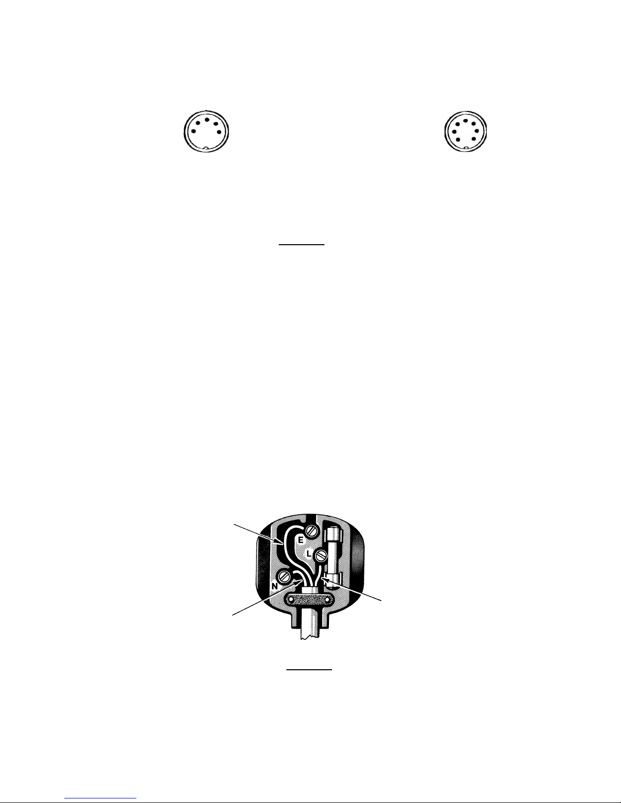
The audio output is via a 5 pin DIN so cket which should be connected to
an audio input o n an amplif ier or tape recorder having a flat frequency
response and an input imped ance greate r than 50 ohms. When a 'straight'
DIN lead (pin 1 connected t o pin 1 etc .) is used, the output level can be
varied from zero to 1V by a d j u s t ment o f t h e pres e t v o l u me co n t r o l s
ad jac ent to the ou tpu t s ock et. (S ee fig. 1) . C onn ect ion to the Lecso n
AC1 is shown in the AC1 instruction manual, fig.4
Page 3
- 2 -
EA RTH EARTH
2 2
AUDI O OUTPU T REMOTE OUTPUT
Rear view of plug
Figure 1
NOTE : If connection is made to th e accessory socket in error, no damage
will result but only one ch annel will be connected to the preamplifier.
The accessory output can be used to drive a centre-zero tuning meter after
removal of an in ternal link connected across the socket. Please note that
once this link is removed, the tuner will not operate unless the two AFC pins
are connected ex ternally.
Do not push in o r pull out DIN plugs w hile the tuner is switched on.
The SFM2 is prot ected by a fuse locate d adjacent to the mains lead entry.
Replacement fuse s must be o f the corre ct type: 20mm 1 amp anti-surge.
Mains supply (220-240V only) to the system is made through the 3 core lead
supplied with th e SFM2. It should be c onnected as shown in Figure 2. The
SFM2 can be adju sted for op eration on 110-120V at the factory if required.
Figure 2
5 Lef t Variable
3 Right Outputs
Right 4
Left 1
N/C 6
5 N/C
3 AFC line
7 AFC line
N/C 4
N/C 1
5 WAY 180 7 WAY
Green/Yellow
Brown
Blue
Page 4
- 3 -
4. CONTROL FUNCTIONS
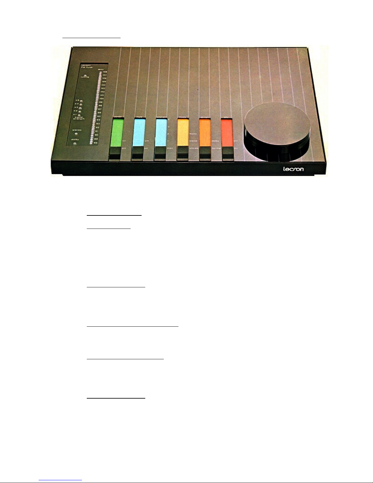
Fig 3 shows the top face of the SFM2, and the control functions are
described below.
4.1. Indicator Lamps .
4.1.1. Tuning Scale . The tuning sc ale consist s of a line array of Light
Emitting Diodes. Usually o ne of these diodes is lit to indicate
the tuning frequ ency select ed by the t uning control. Occasionally
two diodes will be lit wher e the frequ ency selected overlaps
between two disc rete steps. Naturally where only a finite number
of steps are pos sible, the display can not be absolutely accurate,
but serves as a straightfor ward easy-t o-use indication of the
tuning frequency selected.
4.1.2. Tuning Indicator . This LED indi cates the a ccuracy of the setting
of the tuning co ntrol. When the statio n is correctly tuned, the LED
glows. If the Tu ner is more than 40KHz from a station centre
frequency, the l amp will ex tinguish. N OTE: In 'Mute' mode this lamp
also indicates o utput Muted when extin guished.
4.1.3. Signal Strength Indicator . The signal str ength indic ator is
composed of an array of 5 light emitting diodes that are progressively
lit up as the signal strength increases. When all 5 lamps are lit,
the incoming sig nal strengt h is in exc ess of 10mV.
4.1.4. De-emphasis Indicator . This indicator is lit whe never the 2 5 microseconds de-empha sis is sele cted, for instance whenever a Dolby*
encoded signal is receiv ed. It does not in any way indicate that the
received signal is encoded, only that the de-emphasis of this tuner
has been changed .
4.1.5. Stereo Indicator . This indicator is lit whe never a ste reo signal is
received and the mono/stere o switch is set to Stereo or to Stereo
blend.
* Trademark of D olby Labora tories Inc.
Page 5

- 4 -
4.2 CONTROLS
4.2.1. Power Control Switch . This switch c ontrols mai ns power to all the
circuits in the tuner when turned ON. When turned OFF it
disconnects all mains power from all t uner circuits.
4.2.2. Preset Switch . In the normal position, this switch enables the
manual tuning co ntrol knob for selecti on of stations. The remaining
four positions o f the switc h enable th e four pre-set stations. As
the switch is mo ved to each position i t uncovers the associated
pre-set. These p re-sets can be turned to particular stations by
turning them wit h a small s crewdriver or trimmer.
4.2.3. Muting Switch . This switch e nables the muting circ uit, which mutes
the tuner output for very w eak signals so that inter-station hiss
is not heard. Wh en it is se t to OFF al l signals are fed to the
output regardles s of their quality. If the switch is set to ON when
the SFM2 is tuned more than 40KHz from a station centre frequency the
output will be muted in this mode. The Tuner is muted at any time that
the 'ON Channel' LED is extinguished. Due to the narrow tuning window
for each station with Mute ON, we recommend that tuning is carried out
very slowly to avoid over shooting station centres.
4.2.4. Stereo/Mono Switch. This switch is normally set to STEREO position
which enables stereo stations to be received if they are of a suitable
signal strength; during reception of MONO signals (having no 19KHz
Stereo Pilot Tone) the tuner automatically reverts to the mono mode.
The centre position is STEREO BLEND which reduces the noise level when
a stereo signal is received but at the expense of some stereo
separation. The third position is MONO. When the switch is set at
MONO it is not possible to receive any programmes in stereo. Note that
adequate reception of stereo programmes requires a much larger signal
than that necessary for good mono reception.
4.2.5. De-emphasis Switch. In the normal position of this switch the deemphasis time constant is set to that suitable for the area in which
the tuner is used. In the second position the de-emphasis is
recommended whenever Dolby* encoded signals are received and enables
the signal of the correct frequency content to be fed to an external
Dolby type B decoder.
4.2.6. AFC Switch. This switch, the automatic frequency control switch, is
normally set to OFF when the tune control is operated. Once the station
has been selected, setting the switch to ON activates the circuit which
automatically holds the tuner onto the selected station and
compensates for slight manual mis-tuning or any tendency for the tuner
to drift off the station.
4.2.7. Tuning Control . This manual tuning control is a ten-turn rotary
potentiometer which sets the tuner to receive any frequency on the VHF
band from 88 Megahertz to 108 Megahertz.
4.2.8. Preset Volume Controls. (Located on the rear panel). These are used to
match the audio output of the tuner to the inputs of ancillary
equipment such as amplifiers or tape recorders.
* Trademark of Dolby Laboratories Inc.
Page 6

- 5 -
5. TECHNICAL SPECIFICATIONS
Tuning Range: 88 to 108 MHz
Aerial Inputs: 72 Ohm unbalanced, 300 Ohm balanced
Sensitivity: 1.2uV for 30 dB Quieting IHF
IF Rejection: >85 dB
Capture Ratio: 1.2 dB
Frequency Response: 20Hz to 15KHz + 1 dB
T.H.D. (Mono): 0.1% (Typically)
Signal to Noise Ratio (Mono): 70 dB
Pilot Tone Rejection: 60 dB
Stereo Separation: 40 dB at 1KHz
Audio Output: a) Up to 600mV RMS (Variable)
b) Up to 500mV RMS (Fixed)
De-emphasis: 50uS or 25uS switchable (75uS for North
America)
Pre-set Stations: 4 front panel adjustable pre-sets with
visual station indication on LED Tuning
Array
Other Facilities: Automatic Frequency Control. Blend
Facility. Switchable Mute Facility.
Signal Strength Level Indicator. Tuning
Indicator
Accessory Outputs: Local Oscillator Feed to DR1.
Discriminator DC Output to DR1
Overall Dimensions: 363mm wide 250mm deep 38mm high.
 Loading...