

Page 1
Instruction Manual
ZD200 Differential Probe
Page 2
ZD200 Differential
Probe
Instruction Manual
March, 2011
Page 3
LeCroy Corporation
700 Chestnut Ridge Road
Chestnut Ridge, NY, 10977-6499
Tel: (845) 578-6020, Fax: (845) 578 5985
Warranty
LeCroy warrants this oscilloscope accessory for normal use and operation within specification for a period of one
year from the date of shipment. Spare parts, replacement parts and repairs are warranted for 90 days.
In exercising its warranty, LeCroy, at its option, will either repair or replace any assembly returned within its
warranty period to the Customer Service Department or an authorized service center. However, this will be done
only if the product is determined by LeCroy’s examination to be defective due to workmanship or materials, and the
defect is not caused by misuse, neglect, accident, abnormal conditions of operation, or damage resulting from
attempted repair or modifications by a non-authorized service facility.
The customer will be responsible for the transportation and insurance charges for the return of products to the
service facility. LeCroy will return all products under warranty with transportation charges prepaid.
This warranty replaces all other warranties, expressed or implied, including but not limited to any implied warranty
of merchantability, fitness or adequacy for any particular purposes or use. LeCroy shall not be liable for any special,
incidental, or consequential damages, whether in contract or otherwise.
Internet: www.lecroy.com
© 2010 by LeCroy Corporation. All rights reserved.
LeCroy, ActiveDSO, JitterTrack, WavePro, WaveMaster, WaveSurfer, WaveLink,
WaveExpert, Waverunner, and WaveAce are registered trademarks of LeCroy
Corporation. Other product or brand names are trademarks or requested trademarks
of their respective holders. Information in this publication supersedes all earlier
versions. Specifications are subject to change without notice.
Manufactured under
an ISO 9000
Registered Quality
Management System.
Visit www.lecroy.com
to view the
certificate.
This electronic product is subject to
disposal and recycling regulations that
vary by country and region. Many
countries prohibit the disposal of waste
electronic equipment in standard waste
receptacles.
For more information about proper
disposal and recycling of your LeCroy
product, please visit
www.lecroy.com/recycle.
ZD200-GSM-REVA
919314-00 Rev A
Page 4

ZD200 Differential Probe
ZD200-GSM-REVA
iv
TABLE OF CONTENTS
Introduction .......................................................................................... 6
Key Benefits ....................................................................................... 6
Standard Accessories .......................................................................... 7
Features and Accessories ....................................................................... 8
Probe Operation .................................................................................. 10
Handling the Probe .......................................................................... 10
Connecting the Probe to a LeCroy Oscilloscope ................................. 10
Operation with a LeCroy Oscilloscope ............................................... 10
Auto Zero Operation ........................................................................ 11
Connecting the Probe to the Test Circuit ........................................... 11
Care and Maintenance ......................................................................... 12
Cleaning ........................................................................................... 12
Calibration Interval .......................................................................... 12
Service Strategy ............................................................................... 12
Returning a Probe for Calibration or Service ...................................... 13
Returning a Probe to a Different Country .......................................... 14
Replacement Parts ........................................................................... 15
Performance Verification ..................................................................... 16
Performance Verification Overview .................................................. 16
Required Test Equipment ................................................................. 16
Preliminary Procedure ...................................................................... 18
Functional Check .............................................................................. 20
Page 5

ZD200 Differential Probe
ZD200-GSM-REVA
v
Verification Procedure...................................................................... 20
A. LF Attenuation Accuracy .................................................................. 20
Reference Material .............................................................................. 22
Specifications ................................................................................... 22
Contact LeCroy for Support............................................................... 22
Safety Symbols ................................................................................. 24
Operating Environment .................................................................... 25
Safety Requirements ........................................................................ 26
Compliance Information ................................................................... 27
CE Declaration of Conformity .............................................................. 27
Appendix A - Performance Verification Test Record .............................. 29
Items Tested .................................................................................... 29
Equipment Used ............................................................................... 30
Test Record ...................................................................................... 30
LF Attenuation Accuracy ...................................................................... 30
Page 6

ZD200 Differential Probe
ZD200-GSM-REVA
6
Introduction
The ZD200 Differential Probe is ideally suited for automotive
and serial data signals. The wide dynamic range (+/- 20V
differential) and 1 MOhm input resistance make the ZD200
ideally suited for a wide range of applications.
The ZD200 probe can be used with LeCroy’s WaveSurfer,
WaveRunner, WavePro, and WaveMaster series platforms with
firmware version 6.4.1.x or later.
With the ProBus interface, the ZD200 probe becomes an
integral part of the oscilloscope. The probe can be controlled
from the oscilloscope’s front panel. The oscilloscope provides
power to the probe, so there is no need for a separate power
supply or batteries.
Key Benefits
The ZD200 probe features:
1 MOhm input resistance
Low input capacitance
Wide dynamic range
ProBus interface
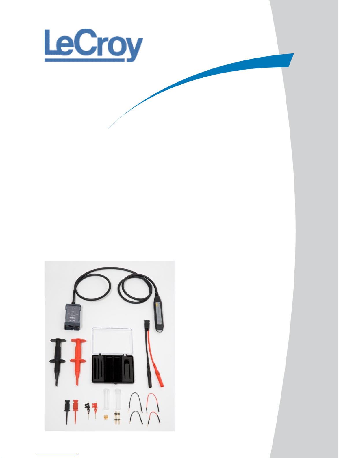
Complete accessory kit consisting of 3 sets of
grabbers, one alligator clip, 2 sets of leads and
2 tip options for probing a variety of test points
Page 7
Instruction Manual
ZD200-GSM-REVA
7
Standard Accessories
The ZD200 probe is shipped with the following standard
accessories:
Standard Accessory
Quantity
Straight Tip
6
Hook Clip
2
Y Leadset
1
Micro IC Clips
2
Micro-Grabbers
2
Extension Leads (5 cm)
2
Extension Leads (10 cm)
2
Dual Pin Set (12.8 mm)
2
Dual pin set (16.8 mm)
2
Instruction Manual
1
Certificate of Calibration
1
Page 8

ZD200 Differential Probe
ZD200-GSM-REVA
8
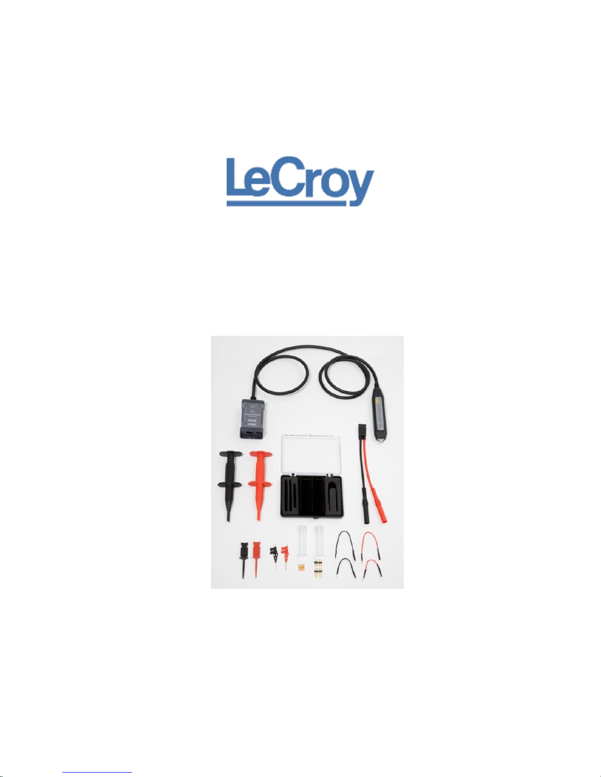
Features and Accessories
The ZD200 probe is provided with numerous features and
accessories to make probing and connecting to different test
points easier than ever.
The small, low mass probe head is designed for ease of
use and high performance.
The probe tip socket fits easily onto 0.025 inch square
pins for direct access to test points. Several different
adapters are available which connect directly in the
probe socket.
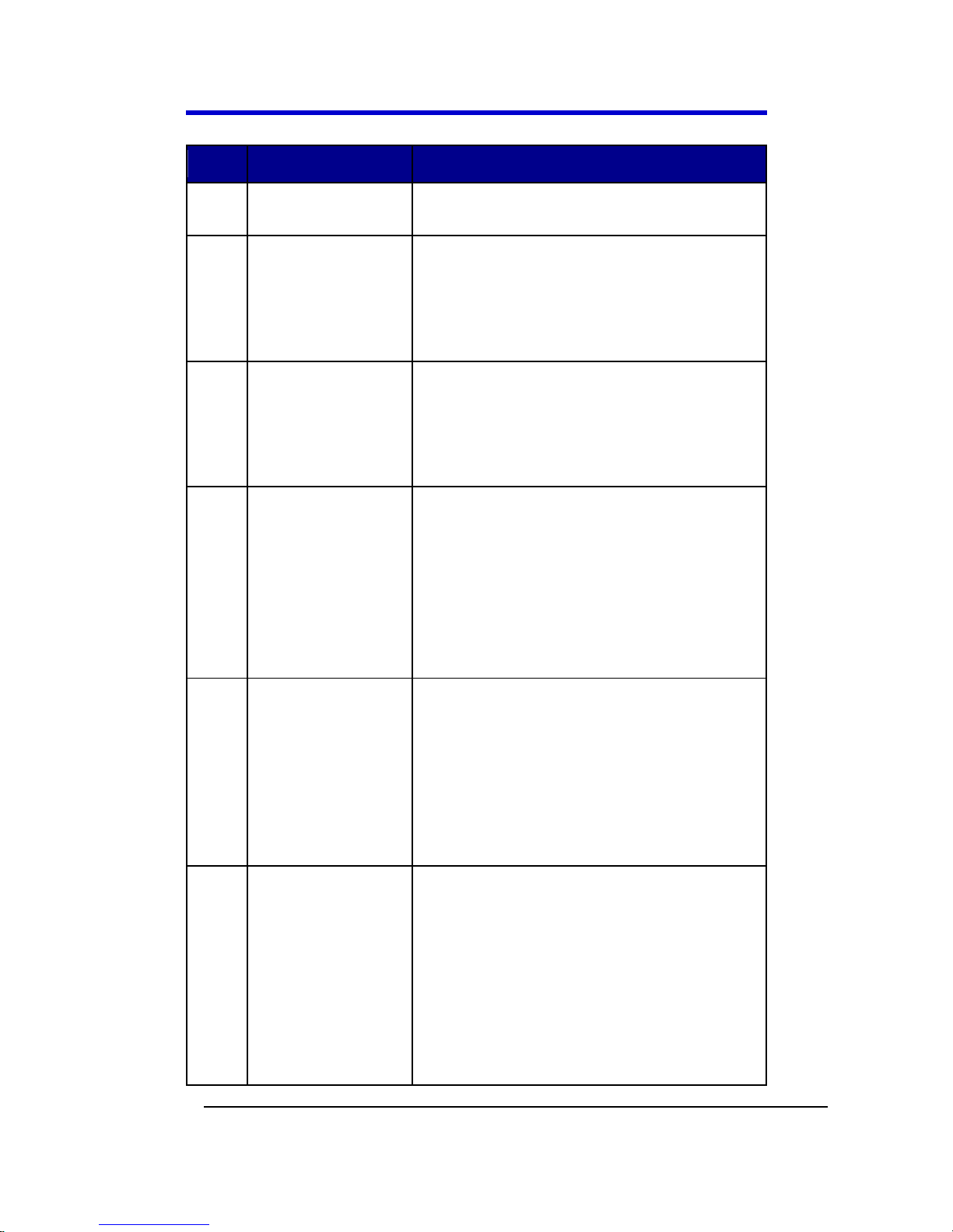
The following image shows the standard accessories for the
ZD200 probe:
Page 9
Instruction Manual
ZD200-GSM-REVA
9
Num
Part
Description
1
Hook Clips
2
Micro-Grabbers
The micro- and mini-grabbers are
ideal for connecting to small IC legs
or pins very tightly spaced.
3
Micro IC
Grabbers
The micro- and mini-grabbers are
ideal for connecting to small IC legs
or pins very tightly spaced.
4
Straight Tips and
Dual Pin Sets
The Straight Tip and Dual Pin Sets are
designed to connect to the smallest
vias and small test points. Fits in
either probe socket.
5
Extension Leads
This lead has a socket on one end and
a square pin on the other to connect
to the input or ground socket of the
probe body, and may be used for
general purpose probing.
6
Y Lead Adapter
This lead is used for both ground and
input lead simultaneously. It has two
sockets on one end for connection to
the provided hook clips and two
square pins on the other and may be
used for general purpose probing.
Page 10
ZD200 Differential Probe
ZD200-GSM-REVA
10
Probe Operation
Handling the Probe
The ZD200 probe is a precision test instrument. Exercise care
when handling and storing the probe. Always handle the probe
by the probe body or compensation box. Avoid putting
excessive strain or exposing the probe cable to sharp bends.
ESD Sensitive: The tips of the ZD200 probes are sensitive to
Electrostatic Discharge (ESD). Avoid causing damage to the
probe by always following anti-static procedures (wear wrist
strap, etc.) when using or handling the probe.
Connecting the Probe to a LeCroy
Oscilloscope
The ZD200 probe has been designed for use with LeCroy’s
WaveSurfer, WaveRunner, WaveMaster, and WavePro
platforms equipped with the ProBus interface. When you
attach the probe output connector to the oscilloscope’s input
connector, the oscilloscope recognizes the probe, provides
proper termination and activates the probe control functions in
the user interface.
Operation with a LeCroy Oscilloscope
When the ZD200 probe is connected to any compatible LeCroy
oscilloscope, the displayed scale factor and measurement
values are automatically adjusted.
Page 11

Instruction Manual
ZD200-GSM-REVA
11
Control through the oscilloscope’s interface can be found on
the channel dialog that corresponds with the connected probe.
Refer to your oscilloscope’s manual for specific operation
instructions.
Turning the Volts/Div knob controls the oscilloscope’s scale
factor to give full available dynamic range up to 5 V/div.
Auto Zero Operation
The scope software includes a feature to null the probe’s
residual offset voltage. The probe should be disconnected from
any signal and the Auto Zero button on the probe menu
pressed. This will measure any residual offset in the probe and
remove it from the measurement.
Connecting the Probe to the Test Circuit
To maintain the high performance capability of the probe in
measurement applications, care must be exercised in
connecting the probe to the test circuit. Increasing the parasitic
capacitance or inductance in the input paths may introduce a
“ring” or slow the rise time of fast signals. Input leads which
form a large loop area will pick up any radiated
electromagnetic field which passes through the loop and may
induce noise into the probe input.
Using one of the available accessories makes the ZD200 probe
with its small profile and low mass head ideally suited for
applications in dense circuitry.
Page 12

ZD200 Differential Probe
ZD200-GSM-REVA
12
Care and Maintenance
Cleaning
The exterior of the probe and cable should be cleaned, using a
soft cloth moistened with water. The use of abrasive agents,
strong detergents, or other solvents may damage the probe.
Always ensure that the input leads are free of debris.
The probe case is not sealed and should never be immersed in
any fluid.
Calibration Interval
The recommended calibration interval is one year.
(Performance Verification and Adjustment Procedures are
included in this manual.)
Service Strategy
The ZD200 probe utilizes fine pitch surface mount devices. It is
therefore impractical to attempt to repair in the field.
Defective probes must be returned to a LeCroy service facility
for diagnosis and exchange. Defective probes under warranty
are repaired or replaced. A probe that is not under warranty
can be exchanged for a factory refurbished probe for a modest
fee. You must return the defective probe in order to receive
credit for the probe core.
Page 13

Instruction Manual
ZD200-GSM-REVA
13
Returning a Probe for Calibration or Service
Return a probe for calibration or service by contacting your
local LeCroy sales representative. They tell you where to return
the product. All returned products should be identified by both
model and serial number. Provide your name and contact
number, and a description of the defect or failure (if possible).
Products returned to the factory require a Return Material
Authorization (RMA) acquired by contacting your nearest
LeCroy sales office, representative or the North America
Customer Care Center.
Return shipment should be prepaid.
LeCroy cannot accept COD or Collect Return
shipments.
We recommend air-freighting.
Note: It is important that the RMA be clearly shown on
the outside of the shipping package for prompt
redirection to the appropriate department.
Use the following steps for a smooth product return.
1. Contact your local LeCroy sales or service
representative to obtain a Return Material
Authorization.
2. Remove all accessories from the probe. Do not
include the manual.
3. Pack the probe in its case, surrounded by the
original packing material (or equivalent) and box.
4. Label the case with a tag containing
The RMA
Name and address of the owner
Probe model and serial number
Page 14

ZD200 Differential Probe
ZD200-GSM-REVA
14
Description of failure
5. Package the probe case in a cardboard shipping box
with adequate padding to avoid damage in transit.
6. Mark the outside of the box with the shipping
address given to you by the LeCroy representative;
be sure to add the following:
ATTN: <RMA assigned by the LeCroy
representative>
FRAGILE
7. Insure the item for the replacement cost of the
probe.
8. Ship the package to the appropriate address.
Returning a Probe to a Different Country
Note: Be sure to properly mark shipments returned for
service from a different country to avoid customs duty for a
full purchase price of a new probe or accessory.
In addition to the items mentioned in the previous topic, mark
shipments returned for service as a Return of US
manufactured goods for warranty repair/recalibration. If
there is a cost involved in the service, put the cost of the
service in the value column and the original value of the
product at time of purchase in the body of the invoice marked
For insurance purposes only.
Be very specific as to the reason for shipment. Duties may have
to be paid on the value of the service.
Page 15

Instruction Manual
ZD200-GSM-REVA
15
Replacement Parts
The probe connection accessories and other common parts can
be ordered through the North America Customer Care Centers.
Replacement Part
Part Number
Accessory Kit
PACC-ZD007
Y-Lead Adapter
PACC-ZD008
Page 16

ZD200 Differential Probe
ZD200-GSM-REVA
16
Performance Verification
Performance Verification Overview
This procedure can be used to verify the warranted
characteristics of the ZD200 High Impedance Active Probe.
The recommended calibration interval for the model ZD200 is
one year. The complete performance verification procedure
should be performed as the first step of annual calibration.
Test results can be recorded on a photocopy of the Test Record
provided in Appendix A at the end of the manual.
Performance verification can be completed without removing
the probe covers or exposing the user to hazardous voltages.
There are no adjustments.
This procedure tests LF Attenuation Accuracy.
Required Test Equipment
The following table lists the test equipment and accessories (or
their equivalents) that are required for performance
verification of the ZD200 Probe.
This procedure has been developed to minimize the number of
calibrated test instruments required.
Only the parameters listed in boldface in the Minimum
requirements column must be calibrated to the accuracy
indicated.
Page 17

Instruction Manual
ZD200-GSM-REVA
17
Because the input and output connector types may vary on
different brands and models of test instruments, additional
adapters or cables may be required.
Description
Minimum
Requirement
Test Equipment
Examples
Digital
Oscilloscope
ProBus Interface;
Windows-based
with software
version 6.4.1.5 or
later
LeCroy WaveRunner
Xi, WavePro Zi or
WaveSurfer Xs
Digital Multimeter
(DMM) with test
probe leads
4.5 digit
DC: 0.1% Accuracy
AC: 0.1% Accuracy
Agilent Technologies
34401A or Fluke
8842A-09
Function
Generator
Sine Wave output
amplitude
adjustable to 14.14
Vp-p (5 Vrms) into 1
MΩ at 70 Hz
Agilent Technologies
33120A or Stanford
Research Model
DS340
Power Supply
0-12 V, settable to
10 mV
HP E3611A
BNC Coaxial Cable
(2 ea.)
Male to Male, 50 Ω,
36" Cable
Pomona 2249-C-36
or Pomona 5697-36
BNC Tee
Connector
Male to Dual
Female
Pomona 3285
Calibration Fixture
ProBus Extender
LeCroy PROBUS-CF01
Page 18

ZD200 Differential Probe
ZD200-GSM-REVA
18
Description
Minimum
Requirement
Test Equipment
Examples
Cable
Terminator,
Precision, BNC
50 Ω ± 0.05%
LeCroy TERM-CF01
Banana Plug
Adapter (2 ea.)
Female BNC to Dual
Banana Plug
Pomona 1269
BNC to Minigrabber
BNC Mail to Minigrabber Cable, 36”
Pomona 5187-C-36
List of Required Equipment
Preliminary Procedure
1. Connect the ZD200 probe to the female end of the
ProBus Extension Cable. Connect the male end of the
ProBus Extension Cable to channel 1 of the
oscilloscope.
2. Turn the oscilloscope on and allow at least 30 minutes
warm-up time for the ZD200 and test equipment
before performing the Verification Procedure.
3. Turn on the other test equipment and allow them to
warm up for the manufacturer’s recommended
timeframe.
4. While the instruments are reaching operating
temperature, make a photocopy of the Performance
Verification Test Record (located in Appendix A), and
fill in the necessary data.
5. Select the channel to which the probe is connected. Set
the oscilloscope scale factor to 20 mV/div.
Page 19

Instruction Manual
ZD200-GSM-REVA
19
6. Disconnect the ProBus Extender Cable from the
oscilloscope. Verify that the scale factor changes from
20 mV/div to 2 mV/div.
7. Reconnect the ProBus extender Cable to the
oscilloscope.
The warranted characteristics of the ZD200 are valid at any
temperature within the Environmental Characteristics listed in
the Specifications. However, some of the other test equipment
used to verify the performance may have environmental
limitations required to meet the accuracy needed for the
procedure. Be sure that the ambient conditions meet the
requirements of all the test instruments used in this procedure.
Note: The correct operation of the ZD200 controls requires
software version 6.4.1.5 or higher. The software version in the
test oscilloscope can be verified by selecting Utilities, Utilities
Setup... from the menu bar, then the Status tab.
Contact your local LeCroy representative or visit
www.lecroy.com if the software in your oscilloscope requires
updating.
Page 20

ZD200 Differential Probe
ZD200-GSM-REVA
20
Functional Check
The functional check will verify the basic operation of the
probe functions.
It is recommended that the Functional Check be performed
prior to the Performance Verification Procedure.
1. Return to the factory default settings by:
a. Selecting File, Recall Setup... from the menu bar.
b. Then touching the Recall Default button.
2. Touch the C1 trace label to open the C1 Vertical Adjust
dialog.
3. Verify that the probe sensed (ZD200) is displayed as a
dialog tab.
Verification Procedure
A. LF Attenuation Accuracy
1. Install the BNC to 2 banana plug into the DMM voltage
inputs.
2. Connect the signal generator output to the to 2 banana
plug on the DMM.
3. Set the DMM to read AC volt and set the range to
AUTO.
4. Set the signal generator to output a 100 Hz sine wave
with amplitude 2 Vrms.
5. Read the AC voltage measured by the DMM and record
on the test data sheet.
6. Divide this value by 10 and record on the test data
sheet.
7. Remove the BNC cable and BNC to 2 banana adapter
from the signal generator and DMM.
8. Install the precision 50Ω termination on the DMM
voltage inputs.
Page 21

Instruction Manual
ZD200-GSM-REVA
21
9. Connect the PROBUS-CF01 BNC male output (the probe
end) to the precision 50Ω termination BNC input. The
probe should remain powered.
10. Install the straight tips on the ZD200 inputs.
11. Connect the signal generator output to the ZD200
inputs using the BNC to mini-grabber cable.
12. Read the voltage from the DMM and record this value
on the test data sheet.
13. Record the calculated error to two decimal places
(±0.xx%) as "Gain Error" in the test record.
14. Verify that the error is less than ±1.0 %.
This completes the Performance Verification of the ZD200.
Complete and file the Test Record, as required to support your
internal calibration procedure.
Apply suitable calibration label to the ZD200 housing as
required.
Page 22

ZD200 Differential Probe
ZD200-GSM-REVA
22
Reference Material
Specifications
Note: Specifications are subject to change without notice.
Please refer to the LeCroy website at www.lecroy.com for
detailed specification information.
Contact LeCroy for Support
Use the following regional contacts to find the appropriate
support location nearest you.
Whether you're looking for sales or technical support, our staff
can provide assistance with installation, calibration, and
product knowledge regarding a full-range of our software
applications and accessories.
You can also find contact information for our offices on the
LeCroy Web site shown for the following regions:
Contact Your Local LeCroy Office for Sales and Technical
Assistance
United States and Canada
Phone (Sales, Applications, and Service): 1-800-553-2769
(options 1, 2, and 3, respectively) or 845-425-2000
Fax (Sales, Applications, and Service): 845-578-5985
Email (Sales, Applications, and Service):
contact.corp@lecroy.com
Web Site: www.lecroy.com/
Korea - Seoul
Phone (Sales and Support): ++ 82
2 3452 0400Fax (Sales and
Support): ++ 82 2 3452 0490
Web Site: www.lecroy.co.kr
Europe
Phone (Sales and Support): + 41
22 719 2228
Fax (Sales and Support): + 41 22
719 2230
Page 23

Instruction Manual
ZD200-GSM-REVA
23
Contact Your Local LeCroy Office for Sales and Technical
Assistance
Email (Sales and Support):
contact.sa@lecroy.com
Web Site:
www.lecroy.com/europe
China
Phone (Sales and Support): ++86
28- 86527180 / 7181 / 7182
Fax (Sales and Support): +86 28-
8652 7183
Email (Sales and Support):
george.ni@lecroy.com
Singapore
Phone (Sales and Support): ++ (65)
64424880
Fax (Sales and Support): ++ (65)
64427811
Email (Sales and Support):
jimmy.ong@lecroy.com
Taiwan
Phone (Sales and Support): (886)
2 8226 1366
Fax (Sales and Support): (886) 2
8226 1368
Email (Sales and Support):
sales_twn@lecoln.com.tw
Web Site: www.lecoln.com.tw
Tokyo
Phone (Sales and Support): ++ 81
3 3376 9400
Fax (Sales and Support): ++ 81 3
3376 9587
Web Site: www.lecroy.com/japan
Page 24

ZD200 Differential Probe
ZD200-GSM-REVA
24
Safety Symbols
The following symbols appear on the accessory or in this
manual and indicate important safety considerations.
Refer to information near this symbol to protect against
personal injury or damage to the instrument.
The CAUTION sign indicates a potential hazard. It calls
attention to a procedure, practice or condition, which, if not
followed, could possibly cause damage to the equipment. If a
CAUTION is indicated, do not proceed until its conditions are
fully understood and met.
The ESD sign indicates a potential hazard. It calls attention to
the susceptibility of the equipment to Electrostatic Discharge
(ESD) induced damage if anti-static measures are not taken.
Page 25

Instruction Manual
ZD200-GSM-REVA
25
Operating Environment
The accessory is intended for indoor use and should be
operated in a clean, dry environment. Before using this
product, ensure that its operating environment is maintained
within these parameters:
Temperature: 5 to 40 °C.
Humidity: Maximum relative humidity 80 % for temperatures
up to 31 °C decreasing linearly to 50 % relative humidity at 40
°C.
Altitude: Up to 10,000 ft (3,048 m).
Note: Direct sunlight, radiators, and other heat sources
should be taken into account when assessing the ambient
temperature.
Page 26

ZD200 Differential Probe
ZD200-GSM-REVA
26
Safety Requirements
CAUTION
Avoid personal injury or damage to your accessory or any
equipment connected to it by reviewing and complying with
the following safety precautions:
Use only as intended. The accessory is intended to be
used only with the compatible LeCroy instruments. Use
of the accessory and/or the equipment it is connected to
in a manner other than specified may impair the
protection mechanisms.
Connect and disconnect properly. Avoid damage
through excessive bending of cables and other
equipment.
Do not use in wet/damp or explosive atmospheres.
For indoor use only. The accessory is intended for indoor
use and should be operated in a clean, dry, environment.
Do not operate with suspected failures. Do not use the
product if any part is damaged. All maintenance should
be referred to qualified service personnel.
Keep product surfaces clean and dry.
Completely assemble the measurement instrument
before circuit/signal contact. Connect probe to the
measurement instrument before connecting the probe
test leads to a circuit/signal being tested.
Do not apply a voltage to any input that exceeds the
maximum rating of that input. Refer to the
Specifications on LeCroy website at www.lecroy.com for
detailed information.
Be careful with sharp tips. Handle the probe with care
as it has sharp tips that may cause bodily injury if not
handled properly.
Page 27

Instruction Manual
ZD200-GSM-REVA
27
Compliance Information
This LeCroy accessory is CE Compliant and bears the CE mark.
CE Declaration of Conformity
This ZD200 Probe meets intent of the European Council
Directive 2006/95/EEC for Product Safety and 2004/108/EEC
for Electromagnetic Compatibility. Compliance was
demonstrated to the following specifications as listed in the
Official Journal of the European Communities:
EN 61010-031:2002 Safety requirements for electrical
equipment for measurement, control, and laboratory
use.
Part 031: Safety requirements for the hand-held probe
assemblies for electrical measurement and test.
The design of the differential probe has been verified to
conform to EN 61010-031 safety standard per the
following limits:
o Installation (Overvoltage) Category I: Refers to
signal level which is applicable for equipment
measuring terminals that are connected to source
circuits in which measures are taken to limit
transient voltages to an appropriate low level.
o Pollution Degree 2: Refers to an operating
environment where normally only dry nonconductive pollution occurs. Occasionally a
temporary conductivity caused by condensation
must be expected.
EN 61326-1:2006, EN 61326-2-1:2006 EMC
requirements for electrical equipment for measurement,
control and laboratory use.
o EN 55011/A2:2002 Radiated and Conducted
Emissions, Group 1, Class A *
Page 28

ZD200 Differential Probe
ZD200-GSM-REVA
28
o EN 61000-4-2:2001 Electrostatic Discharge
Immunity (±4 kV contact discharge, ±4 kV air
discharge, ±4 kV vertical/horizontal coupling
planes )
o EN 61000-4-3:2006 RF Radiated Electromagnetic
Field Immunity (3 V/m, 80 MHz to 1 GHz; 3 V/m,
1.4 GHz to 2 GHz; 1 V/m, 2 GHz to 2.7 GHz , 80%
amplitude modulated with 1 kHz sinewave)
* This product is intended for use in nonresidential areas only.
Use in residential areas may cause electromagnetic
interference.
Page 29

Instruction Manual
ZD200-GSM-REVA
29
Appendix A - Performance
Verification Test Record
This record can be used to record the results of measurements
made during the performance verification of the ZD200 Probe.
Photocopy this page and record the results on the copy. File
the completed record as required by applicable internal quality
procedures. The section in the test record corresponds to the
parameters tested in the performance verification procedure.
The numbers preceding the individual data records correspond
to the steps in the procedure requiring the recording of data.
Results to be recorded in the column labeled Test Result are
the actual specification limit check. The test limits are included
in all of these steps. Other measurements and the results of
intermediate calculations that support the limit check are to be
recorded in the column labeled Intermediate Results.
Permission is granted to reproduce these pages for the
purpose of recording test results.
Note: Use a new Test Record for each tested probe, probe tip
module, and lead assembly.
Items Tested
Item
Serial Number
Date
Technician
ZD200
Page 30

ZD200 Differential Probe
ZD200-GSM-REVA
30
Equipment Used
Instrument
Model
Serial
Number
Calibration Due
Date
Oscilloscope
Digital Multimeter
Function
Generator
Note: The function generator used in this Performance
Verification Procedure is used for making relative
measurements. The output of the generator is measured with
a DMM or oscilloscope in this procedure. Thus, the generator
is not required to be calibrated.
Test Record
LF Attenuation Accuracy
Step
Description
Intermediate Data
A-5
Generator Output
Voltage
V
A-6
Expected Output Voltage
V
A-12
Measured Output Voltage
V
A-13
Gain Error, top range
(Test Limit ≤ ± 1.0%)
%
Page 31

Instruction Manual
ZD200-GSM-REVA
31
Thank you for purchasing a
ZD200 Differential Probe.
 Loading...