

Page 1
LECROY
WAVEJET 300 SERIES
O
SCILLOSCOPES
REMOTE CONTROL MANUAL
FEBRUARY 2007
Page 2

LeCroy Corporation
700 Chestnut Ridge Road
Chestnut Ridge, NY 10977–6499
Tel: (845) 578 6020, Fax: (845) 578 5985
Internet: www.lecroy.com
© 2007 by LeCroy Corporation. All rights reserved.
LeCroy, ActiveDSO, WaveLink, JitterTrack, WavePro, WaveMaster, WaveSurfer, WaveExpert, WaveJet, and
Waverunner are registered trademarks of LeCroy Corporation. Other product or brand names are trademarks or
requested trademarks of their respective holders. Information in this publication supersedes all earlier versions.
Specifications subject to change without notice.
This electronic product is subject to
disposal and recycling regulations
that vary by country and region.
Manufactured under an ISO 9000
Registered Quality Management System
Visit www.lecroy.com to view the
certificate.
Many countries prohibit the
disposal of waste electronic
equipment in standard waste
receptacles.
For more information about proper
disposal and recycling of your
LeCroy product, please visit
www.lecroy.com/recycle.
WJ-RCM-E Rev B
914866
Page 3

WaveJet Remote Control Manual
1. INTRODUCTION....................................................................................................................3
1.1 WJ-GPIB Hardware .........................................................................................................................3
1.2 WJ-LAN Hardware...........................................................................................................................3
2. INSTALLATION OF GPIB AND TCP/IP ................................................................................ 4
WaveJet Remote Control Interface Installation Procedure................................................................................. 4
2.1 List of IEEE 488.1 interface functions subsets implemented...........................................................5
2.2 Device behavior when the address is changed outside the range 0 to 30 ......................................5
2.3 When a user-initiated address change is recognized by the device................................................5
2.4 Device setting at power-on, including commands which modify the power-on settings .................. 5
2.5 Message exchange options.............................................................................................................5
Size and behavior of input buffer ........................................................................................................................ 5
Queries that return more than one <RESPONSE MESSAGE UNIT>................................................................ 5
Queries that generate a response when parsed ................................................................................................ 5
Queries that generate a response when read .................................................................................................... 5
Commands that are coupled............................................................................................................................... 5
2.6 Functional elements used in constructing device-specific commands ............................................6
2.7 Buffer size limitations related to block data .....................................................................................7
2.8 List of <PROGRAM DATA> elements .............................................................................................7
2.9 Response syntax for every query. ...................................................................................................7
2.10 Device-to-device message transfer traffic that does not follow the rules for <RESPONSE
MESSAGE> elements ...........................................................................................................................8
2.11 Size of block data responses.........................................................................................................8
2.12 List of common commands and queries which are implemented ..................................................8
2.13 State of the device after successful completion of the Calibration query ......................................9
2.14 Maximum length of the block used to define the trigger macro, if *DDT is implemented ..............9
2.15 Macro parameters..........................................................................................................................9
2.16 Response to the identification common query, *IDN? .................................................................10
2.17 Size of protected user data storage area if the *PUD command and *PUD? query are implemented
.............................................................................................................................................................10
2.18 Size of resource description if the *RDT command or *RDT? query are implemented. .............. 10
2.19 States affected by *RST, *LRN?, *RCL, and *SAV......................................................................10
2.20 Scope of self-test performed by the *TST? query........................................................................10
2.21 Additional status data structures used in the device’s status reporting .......................................10
Status Byte Register ......................................................................................................................................... 10
Service Request Enable Register..................................................................................................................... 10
Standard Event Status Register ....................................................................................................................... 11
Standard Event Status Enable Register ........................................................................................................... 11
Trigger Event Status Register........................................................................................................................... 11
Trigger Event Status Enable Register .............................................................................................................. 11
2.22 For each command, a statement describing whether it is overlapped or sequential ................... 11
2.23 For each command device, the documentation shall specify the functional criteria that are met
when an operation complete message is generated in response to that command............................11
WJ-RCM-E Rev B 1
Page 4

WaveJet 300 Series
3. REMOTE MENU ..................................................................................................................12
4. LIMITATIONS ON REMOTE FUNCTION............................................................................ 13
5. RESPONSE FORMATS ...................................................................................................... 14
6. REMOTE COMMANDS ....................................................................................................... 15
2 WJ-RCM-E Rev B
Page 5

WaveJet Remote Control Manual
1. INTRODUCTION
The WJ-GPIB and WJ-LAN are interface boards exclusively for the WaveJet3xx series.
• Insert the board into one of the option slots on the rear of the WaveJet3xx before use.
• It can be inserted into either of the two option slots provided.
• Once the board is inserted into the slot, the WaveJet main unit automatically recognizes it as a remote
interface, allowing you to select it.
• The WJ-GPIB and the WJ-LAN can be inserted at the same time, but only one of them can be selected.
• Two of the same kind of interface board must not be inserted at the same time (prohibited).
CAUTION!
To prevent damage to the instrument, turn instrument power OFF before inserting a
WJ-GPIB or WJ-LAN interface board.
ESD Sensitive
The WJ-GPIB and WJ-LAN interface boards are sensitive to electrostatic discharge (ESD).
To avoid causing damage to the boards, always follow anti-static procedures (wear wrist
strap, etc.) when handling the boards.
1.1 WJ-GPIB Hardware
Applicable standard GPIB IEEE-488.1
Usable unit WaveJet 3xx series firmware 3.xx or later
Power supply Supplied from WaveJet3xx option slot
Power consumption Included in WaveJet3xx main unit
Dimensions
Mass Approximately 70 g
Operating temperature
range
Operating humidity range
Storage temperature range
1.2 WJ-LAN Hardware
Applicable standard
Usable unit WaveJet 3xx series firmware 3.xx or later
Power supply Supplied from WaveJet3xx option slot
Power consumption Included in WaveJet3xx main unit
Dimensions
Mass Approximately 55 g
Operating temperature
range
Operating humidity range
Storage temperature range
63 mm × 80 mm (excluding protrusion of connector terminal)
0 to 40 °C
80% RH or lower (when operated within 0 to 40 °C)
-20 to +60 °C
TCP/IP 10BASE-T/100BASE-T
63 mm × 80 mm (excluding protrusion of connector terminal)
0 to 40 °C
80% RH or lower (when operated within 0 to 40 °C)
-20 to +60 °C
WJ-RCM-E Rev B 3
Page 6

WaveJet 300 Series
2. INSTALLATION OF GPIB AND TCP/IP
The Remote Function uses GPIB and TCP/IP as the interface. GPIB is installed according to IEEE488.1 and
IEEE488.2, while TCP/IP is installed according to LeCroy VICP.
WaveJet Remote Control Interface Installation Procedure
The WaveJet remote control interfaces, WJ-LAN and WJ-GPIB are compatible with all WaveJet units running
firmware version 3.06 or higher. For firmware upgrades please visit www.lecroy.com. The firmware and firmware
installation instructions are available for download.
1. Confirm the installed firmware version is 3.06 or higher. To do this press U
Status and Update and then select Update. If it is 3.06 or greater proceed to step 2. If not please update the
firmware.
2. With the power off, remove the screws from the rear panel option slot.
3. Insert the WJ-LAN and/or WJ-GPIB interfaces into the slot and fasten the screws.
4. Turn the WaveJet power on and then press U
5. In the Utilities menu a new selection, Remote will be available, if two cards are installed there will be a choice
between TCP/IP and GPIB. If only one is installed there will only be one listing.
6. For GPIB operation use the A
7. For TCP/IP use the A
jump from field to field. The WaveJet works with static IP addressing only.
8. Press the soft key next to the down arrow to move to Subnet Mask and Default Gateway. Rotate the knob to
enter values; push the knob to change fields.
9. After entering the correct addresses, press Enter at the bottom of the remote menu and reboot the scope.
The WaveJet can be operated with both WJ-LAN and WJ-GPIB installed, or with only one interface card installed.
However, two GPIB or two LAN cards cannot be installed simultaneously.
DJUST knob to set the IP address. Rotate the knob to change values; push the knob to
DJUST knob to set the appropriate GPIB address.
TILITIES on the front panel.
TILITIES on the front panel, select
4 WJ-RCM-E Rev B
Page 7

WaveJet Remote Control Manual
2.1 List of IEEE 488.1 interface functions subsets implemented
Table 2-1. List of IEEE 488.1 interface functions
subsets implemented
Interface function Subset
Source Handshake SH1
Acceptor Handshake AH1
Talker T6,TE0
Listener L4, LE0
Service Request SR1
Remote Local RL2
Parallel Poll PP0
Device Clear DC1
Device Trigger DT1
Controller C0
Electrical Interface E2
2.2 Device behavior when the address is changed outside the range 0 to 30
• With GPIB, values that do not fall within the range of 0 to 30 cannot be selected.
• TCP/IP has 4 fields, IPv4, for which values that do not fall within the range of 0 to 255 cannot be selected.
2.3 When a user-initiated address change is recognized by the device
• GPIB immediately recognizes the address change.
• TCP/IP recognizes the change when the system is rebooted after the change.
2.4 Device setting at power-on, including commands which modify the power-on settings
• At power-on, device settings are restored to their values when the device was last powered off.
• A command for changing the power-on settings is not installed.
2.5 Message exchange options
Size and behavior of input buffer
The size of the input buffer is 512 bytes.
Queries that return more than one <RESPONSE MESSAGE UNIT>
See the list of commands.
Queries that generate a response when parsed
See the list of commands.
Queries that generate a response when read
See the list of commands.
Commands that are coupled
See the list of commands.
WJ-RCM-E Rev B 5
Page 8
WaveJet 300 Series
2.6 Functional elements used in constructing device-specific commands
Whether <compound command program header> elements are used must also be included.
Table 2-2. Device listening functional elements
Element Implemented?
<PROGRAM MESSAGE> Yes
<PROGRAM MESSAGE TERMINATOR> Yes
<PROGRAM MESSAGE UNIT> Yes
<PROGRAM MESSAGE UNIT SEPARATOR> Yes
<COMMAND MESSAGE UNIT> Yes
<QUERY MESSAGE UNIT> Yes
<COMMAND PROGRAM HEADER> Yes
<QUERY PROGRAM HEADER> Yes
<PROGRAM HEADER SEPARATOR> Yes
<PROGRAM DATA SEPARATOR> Yes
<PROGRAM DATA> Yes
<DECIMAL NUMERIC PROGRAM DATA> Yes
<CHARACTER PROGRAM DATA> Yes
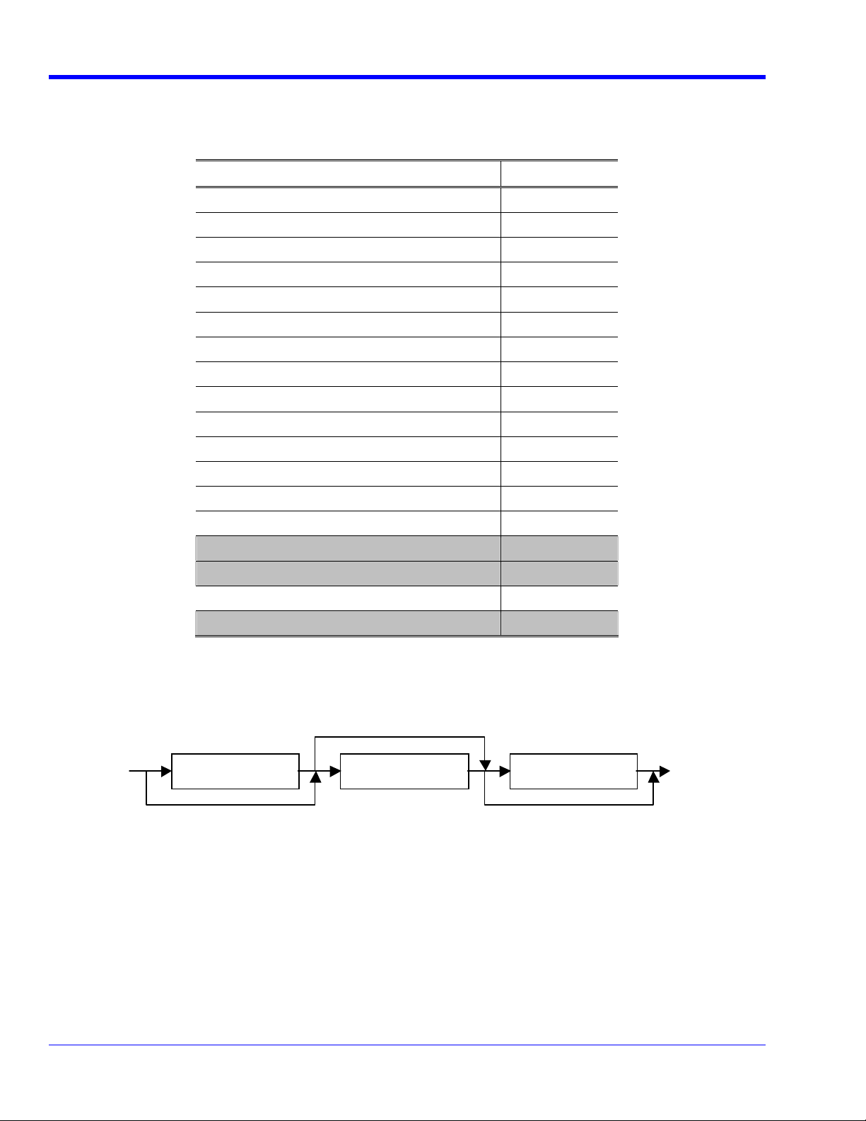
<SUFFIX PROGRAM DATA> Yes (see Figure 2-1)
<NON-DECIMAL NUMERIC PROGRAM DATA> No
<STRING PROGRAM DATA> No
<ARBITRARY BLOCK PROGRAM DATA> Yes
<EXPRESSION PROGRAM DATA> No
<w hite space> <suffix m ult> <suffix unit>
Figure 2-1. <SUFFIX PROGRAM DATA> element
• Enter <white space> according to IEEE488.2.
• Enter <suffix mult> in <upper/lower case alpha> according to IEEE488.2.
• Enter <suffix unit> according to IEEE488.2.
The following combinations only can be used for <compound command program header>.
6 WJ-RCM-E Rev B
Page 9

WaveJet Remote Control Manual
Table 2-3. List of <compound command program header>
Selectable Depth1 Element Selectable Depth2 Element
C1, C2, C3, C4 and M1 VDIV Command/Query
C1, C2, C3, C4 and M1 OFST Command/Query
C1, C2, C3, C4 and M1 TRA Command/Query
C1, C2, C3 and C4 CPL Command/Query
C1, C2, C3 and C4 PROBE Command/Query
C1, C2, C3 and C4 BWL Command/Query
2.7 Buffer size limitations related to block data
• If data exceeding the input buffer limit is received, the excess data is discarded until a delimiter is detected.
• If data exceeding the output queue limit is transmitted, commands that are not interpreted and excess data
are discarded.
2.8 List of <PROGRAM DATA> elements
These may appear within an <expression>, and maximum sub-expression nesting depth.
Table 2-4. List of <PROGRAM DATA> elements
Element Implemented?
<CHARACTER PROGRAM DATA> Yes
<DECIMAL NUMERIC PROGRAM DATA> Yes
<SUFFIX PROGRAM DATA> Yes (see Figure 2-1)
<NON-DECIMAL NUMERIC PROGRAM DATA> No
<STRING PROGRAM DATA> No
<ARBITRARY BLOCK PROGRAM DATA> Yes
<EXPRESSION PROGRAM DATA> No
2.9 Response syntax for every query.
Table 2-5. Device listening functional elements
Element Implemented?
<RESPONSE MESSAGE> Yes
<RESPONSE MESSAGE TERMINATOR> Yes
<RESPONSE MESSAGE UNIT> Yes
<RESPONSE MESSAGE UNIT SEPARATOR> Yes
<RESPONSE DATA> Yes
<RESPONSE DATA SEPARATOR> Yes
<NR1 NUMERIC RESPONSE DATA> Yes
<ARBITRARY ASCII RESPONSE DATA> Yes
<RESPONSE HEADER SEPARATOR> No
<RESPONSE HEADER> No
<CHARACTER RESPONSE DATA> Yes
WJ-RCM-E Rev B 7
Page 10

WaveJet 300 Series
<NR2 NUMERIC RESPONSE DATA> No
<NR3 NUMERIC RESPONSE DATA> Yes
<HEXADECIMAL RESPONSE DATA> No
<BINARY NUMERIC RESPONSE DATA> No
<STRING RESPONSE DATA> No
<DEFINITE LENGTH ARBITRARY BLOCK
RESPONSE DATA>
<INDEFINITE LENGTH ARBITRARY BLOCK
RESPONSE DATA>
2.10 Device-to-device message transfer traffic that does not follow the rules for <RESPONSE
MESSAGE> elements
None.
2.11 Size of block data responses
Block data response is made for DTWAVE query, DTSTUP query, and TSCRN query.
Table 2-6. Size of block data responses (MLEN 500K,
DTPOINTS 500000 and DTSTART 0)
Yes
No
Query Status Size of block data
DTWAVE? Normal Sampling 500,010 bytes
DTWAVE? Average Sampling 1,000,010 bytes
DTWAVE? Multiplication Wave 2,000,010 bytes
DTWAVE? Other Sampling 500,010 bytes
DTSTUP? (Constant) 476 bytes
TSCRN? TIFF 308,956 bytes
TSCRN? BMP 308,288 bytes
TSCRN? PNG (Variable)
2.12 List of common commands and queries which are implemented
Table 2-7. List of common commands and queries
Mnemonic Name Implemented?
*AAD Accept Address Command No
*CAL? Calibration Query No
*CLS Clear Status Command Yes
*DDT Define Device Trigger Command No
*DDT? Define Device Trigger Query No
*DLF Disable Listener Function Command No
*DMC Define Macro Command No
*EMC Enable Macro Command No
*EMC? Enable Macro Query No
*ESE Standard Event Status Enable Command Yes
8 WJ-RCM-E Rev B
Page 11

WaveJet Remote Control Manual
*ESE? Standard Event Status Enable Query Yes
*ESR? Standard Event Status Register Query Yes
*GMC? Get Macro Contents Query No
*IDN? Identification Query Yes
*IST? Individual Status Query No
*LMC? Learn Macro Query No
*LRN? Learn Device Setup Query No
*OPC Operation Complete Command Yes
*OPC? Operation Complete Query Yes
*OPT? Option Identification Query No
*PCB Pass Control Back Command No
*PMC Purge Macro Command No
*PRE Parallel Poll Register Enable Command No
*PRE? Parallel Poll Register Enable Query No
*PSC Power On Status Clear Command No
*PSC? Power On Status Clear Query No
*PUD Protected User Data Command No
*PUD? Protected User Data Query No
*RCL Recall Command Yes
*RDT Resource Description Transfer Command No
*RDT? Resource Description Transfer Query No
*RST Reset Command Yes
*SAV Save Command Yes
*SRE Service Request Enable Command Yes
*SRE? Service Request Enable Query Yes
*STB? Read Status Byte Query Yes
*TRG Trigger Command Yes
*TST? Self-Test Query Yes
*WAI Wait-to-Continue Command Yes
2.13 State of the device after successful completion of the Calibration query
Not implemented.
2.14 Maximum length of the block used to define the trigger macro, if *DDT is implemented
Not implemented.
2.15 Macro parameters
Maximum length of macro labels, maximum length of the block used to define a macro, and how recursion
is handled during macro expansion, if macro commands are implemented
Not implemented.
WJ-RCM-E Rev B 9
Page 12

WaveJet 300 Series
2.16 Response to the identification common query, *IDN?
See the list of commands.
2.17 Size of protected user data storage area if the *PUD command and *PUD? query are
implemented
Not implemented.
2.18 Size of resource description if the *RDT command or *RDT? query are implemented.
Not implemented.
2.19 States affected by *RST, *LRN?, *RCL, and *SAV
Table 2-8. List of states affected
Name State
*RST Same as Recall Default Setup
*LRN Not implemented
*RCL Same as Recall Setup
*SAV Same as Save Setup
2.20 Scope of self-test performed by the *TST? query
The Acquisition Memory test is conducted.
2.21 Additional status data structures used in the device’s status reporting
Status Byte Register
Table 2-9. Model of Status Byte Register
Bit Definition Implemented?
7 Device-Defined Summary Message No (always zero)
6 Master Summary Status Yes
5 Standard Event Status Bit (ESB) Summary Message Yes
4 MAV Queue Summary Message Yes (only GPIB)
3 Device-Defined Summary Message No (always zero)
2 Device-Defined Summary Message No (always zero)
1 Device-Defined Summary Message No (always zero)
0 Trigger Event Status Bit (TESB) Summary Message Yes
Service Request Enable Register
An application programmer can select which summary messages in the Status Byte Register may cause
service requests.
10 WJ-RCM-E Rev B
Page 13

Standard Event Status Register
Table 2-10. Model of Standard Event Status Register
Bit Definition Implemented?
7 Power On (PON) Yes
6 User Request (URQ) No (always zero)
5 Command ERROR (CME) Yes
4 Execution ERROR (EXE) Yes
3 Device-Specific Error (DDE) Yes
2 Query ERROR (QYE) Yes (only GPIB)
1 Request Control (RQC) No (always zero)
0 Operation Complete (OPC) Yes
Standard Event Status Enable Register
The Standard Event Status Enable Register allows one or more events in the Standard Event Status
Register to be reflected in the ESB summary-message bit.
Trigger Event Status Register
Table 2-11. Model of Trigger Event Status Register
WaveJet Remote Control Manual
Bit Definition Implemented?
7 Always zero No
6 Always zero No
5 Always zero No
4 Always zero No
3 Always zero No
2 Always zero No
1 Always zero No
0 Single Wave Enable (SWE) Yes
Trigger Event Status Enable Register
The Trigger Event Status Enable Register allows one or more events in the Standard Event Status Register
to be reflected in the TESB summary-message bit.
2.22 For each command, a statement describing whether it is overlapped or sequential
Overlapped commands are not provided.
2.23 For each command device, the documentation shall specify the functional criteria that are
met when an operation complete message is generated in response to that command.
• Overlapped commands are not provided.
• The operation is completed on receipt of the command.
WJ-RCM-E Rev B 11
Page 14

WaveJet 300 Series
3. REMOTE MENU
If the option board is mounted, Remote can be selected from the Utilities menu.
The Remote menu is configured as follows.
• Communication is performed only through the interface selected.
• IP Address, Subnet Mask, and Default Gateway can be set for the IP Address Dialog.
• The IP Address Dialog displays the MAC Address.
Table 3-1. When Interface is set to Off
Menu Function
Interface Off
Not used
Not used
Not used
Not used
Table 3-2. When GPIB is selected as Interface
Menu Function
Interface GPIB
Address GPIB Address
Not used
Not used
Not used
Table 3-3. When TCP/IP is selected as Interface
Menu Function
Interface TCP/IP
IP Address IP Address Menu display function
IP Address Menu cursor down
function
Not used
Enter Sets the current IP Address.
12 WJ-RCM-E Rev B
Page 15

WaveJet Remote Control Manual
4. LIMITATIONS ON REMOTE FUNCTION
The following limitations are imposed when Remote Control is selected.
• Delimiters permit the following settings.
Table 4-1. Delimiters
State Delimiter
Recv EOI only
Recv CR+EOI
Recv LF+EOI
Recv CR+LF+EOI
Send LF+EOI
• Panel Lock mode is entered.
• The setting is changed to the following once Remote Control mode is entered.
Table 4-2. Setup in Remote Control mode
Item Setup Panel
Help display Off -
Offset Setting Division Utilities/Config. 1/2
Power Off Never Utilities/Config. 1/2/Power
Management
Panel Lock Lock Utilities/Config. 2/2
Volts/div Coarse Channel Menu 2/2
Zoom Off ZOOM
Line Number (TV Standard = NTSC) 263/262 Trigger Menu/Type = TV/TV Setting
Line Number (TV Standard = PAL) 625 Trigger Menu/Type = TV/TV Setting
WJ-RCM-E Rev B 13
Page 16

WaveJet 300 Series
5. RESPONSE FORMATS
The following response formats are provided according to the settings of the DTFORM and DTBOARD commands.
The number of data to be transferred may vary depending on the settings of the DTSTART and DTPOINTS
commands.
(1) The DTFORM command is set to "BYTE/WORD" (binary transfer):
#8 <byte-length> <binary-block>
• #8 shows that the response message is described in the format of <Definite Length Arbitrary Block
Response Data> and that the content of the following <byte_length> is an 8-digit ASCII string.
• The contents of <byte_length> represents the number of bytes to be entered into <binary_block>. The
byte length should always be a sign-free, 8-digit integer including zero.
• The contents of <binary_block> represents the waveform data stored in the product's internal memory
in binary code.
[Example of data]
# 8 0 0 0 0 1 0 2 4 D0 D1 - - - Dn
1024-byte binary data (D0, D1,..., Dn) is transferred.
(a) The DTFORM command is set to "BYTE":
• Since one unit of data is transferred in one byte, the number of bytes meets the number of transfer
data specified using the DTPOINTS command.
[Example of data]
# 8 0 0 0 0 1 0 2 4 D0 D1 - - - Dn
1024-byte binary data is transferred, and Di (i = 1, 2,..., n) corresponds to one unit of data.
Note 1: For average waveforms, only upper bytes are transferred, even though these waveforms are word
data.
Note 2: For math waveforms, word (for ADD/SUB/FFT) or double word (for MULT) data is transferred even
though the DTFORM setting is BYTE.
(b) The DTFORM command is set to "WORD":
• Since one unit of data is transferred in two bytes, the number of bytes to be transferred is twice as
large as the number of transfer data specified using the DTPOINTS command.
[Example of data]
# 8 0 0 0 0 2 0 4 8 U0 L0 U1 L1 - - - Un Ln
• 2048-byte binary data (U0, L0, U1, L1,..., Un, Ln) is transferred.
• Two bytes Ui and Li (i = 1, 2,..., n) correspond to one unit of data.
• For channel waveforms other than averaged, Li (i = 0, 1, …, n) becomes 0.
• The DTBORD command is used to specify the byte order. When L/H is specified, the data is
transferred in the order of Li, Ui (i = 0, 1,..., n).
(2) The DTFORM command is set to "ASCII":
<ascii_block> <delimiter>
• <ascii_block> contains block data. The waveform data units stored in the product's internal memory
are described in the format of <NR1 Numeric Response Data> one by one, and these data units are
respectively separated by a comma.
[Example of data]
D0, D1,..., Dn
Di (i = 0, 1,..., n) is described in the format of <NR1 Numeric Response Data>.
14 WJ-RCM-E Rev B
Page 17

WaveJet Remote Control Manual
6. REMOTE COMMANDS
This list of remote commands is alphabetized by short form.
Horizontal ACQ
Command/Query
DESCRIPTION The ACQ command selects the acquisition mode. The ACQ?
query returns the current selection of the acquisition
mode.
COMMAND SYNTAX ACQ <mode>
<mode>:={NORMAL, PEAK, AVERAGE} (When XYDS is YT)
<mode>:={NORMAL, AVERAGE} (When XYDS is XYTRG)
<mode>:={NORMAL} (When XYDS is XY)
QUERY SYNTAX ACQ?
RESPONSE FORMAT <mode>
REMARKS ACQ AVERAGE sets ROLL OFF automatically.
Acquisition ASET
Command
DESCRIPTION The ASET command provides the auto setup.
COMMAND SYNTAX ASET
QUERY SYNTAX
RESPONSE FORMAT
Horizontal AVGCNT
Command/Query
DESCRIPTION The AVGCNT command sets the number of events to average.
AVGCNT? query returns the number set.
COMMAND SYNTAX AVGCNT <number>
<number>:={2, 4, 8, 16, 32, 64, 128, 256}
QUERY SYNTAX AVGCNT?
RESPONSE FORMAT <number>
REMARKS AVGCNT command reports device-specific error (DDE) and
is not performed when ACQ is not AVERAGE.
Vertical BWL
Command/Query
DESCRIPTION The BWL command enables or disables the bandwidth limit
(low-pass filter) of the specified input channel. The
BWL? query returns the selected status.
COMMAND SYNTAX <channel>: BWL <mode>
<channel>: = {C1, C2, C3, C4} (WJ354/334/324/314)
: = {C1, C2} (WJ352/332/322/312)
<mode>: = {OFF, 100M, 20M} (WJ354/334/352/332)
: = {OFF, 20M} (WJ324/314/322/312)
QUERY SYNTAX <channel>:BWL?
RESPONSE FORMAT <mode>
The current bandwidth limit status (low-pass filter)
WJ-RCM-E Rev B 15
Page 18

WaveJet 300 Series
is identified in <mode>.
REMARKS WJ 324, WJ314, WJ322 and WJ312 set the bandwidth limiter
to 20 MHz when these scopes receive "BWL 100M".
Status *CLS
Command
DESCRIPTION The *CLS command clears the entire status data
register.
COMMAND SYNTAX *CLS
QUERY SYNTAX
RESPONSE FORMAT
Cursor CMSR?
Query
DESCRIPTION The CMSR? query returns the currently displayed cursor
measurements.
COMMAND SYNTAX
QUERY SYNTAX CMSR?
RESPONSE FORMAT <measure1>, <measure2>, <measure3>, <measure4>,
<measure5>, <measure6>, <measure7>
• Current cursor measurements are displayed in
<measure1> to <measure7> in
<NR3 Numeric Response Data> format.
• When the cursor mode is disabled or the data cannot
be measured, the query returns +9.91E+37.
• Seven types of cursor measurement results are output,
respectively separated by a comma, regardless of
whether cursor mode has been selected. For items not
covered by the measurement, the query returns
+9.91E+37.
• The table below shows the relationship between
<measure1> to <measure7> and
cursor mode.
<measure1>:= CH1
<measure2>:= CH2
<measure3>:= CH3
<measure4>:= CH4
<measure5>:= MATH
<measure6>:= delta t
<measure7>:= 1 / delta t
When MATH is FFT, M1:TRA is ON and CURM is VATH, CMSR?
returns frequency at the cursor of the FFT waveform for
<measure7>.
REMARKS When calculating the cursor measurement values of the
YT display Amplitude, Value at Cursor, and XY display
ch Amplitude in the model WJ352/332/322/312,
<measure3> and <measure4> return "+9.91E+37".
16 WJ-RCM-E Rev B
Page 19

WaveJet Remote Control Manual
Hard Copy COPY
Command
DESCRIPTION The COPY command copies the current screen data to USB
Memory.
COMMAND SYNTAX COPY
QUERY SYNTAX
RESPONSE FORMAT
Vertical CPL
Command/Query
DESCRIPTION The CPL command sets the coupling mode of the specified
input channel. The CPL? query returns the selected
coupling mode.
COMMAND SYNTAX <channel>:CPL <coupling>
<channel>:={C1, C2, C3, C4} (for WJ354/334/324/314)
:={C1, C2} (for WJ352/332/322/312)
<coupling>:={AC1M, GND, DC1M, DC50} (for
WJ354/334/352/332)
:={AC1M, GND, DC1M} (for
WJ324/314/322/312)
QUERY SYNTAX <channel>:CPL?
RESPONSE FORMAT <coupling>
The current coupling mode is identified in <coupling>.
Cursor CURM
Command/Query
DESCRIPTION The CURM command defines the cursor mode. The CURM?
query returns the defined cursor mode.
COMMAND SYNTAX CURM <mode>
<mode>: = {OFF, DV, DH, DHDV, VATH}
QUERY SYNTAX CURM?
RESPONSE FORMAT <mode>
System DATE
Command/Query
DESCRIPTION The DATE command defines the date and time. The DATE?
query reads the defined date and time.
COMMAND SYNTAX DATE <day>,<month>,<year>,<hour>,<minute>,<second>
<day>:= a number from 1 to 31.
<month>:= {JAN, FEB, MAR, APR, MAY, JUN, JUL, AUG, SEP,
OCT, NOV, DEC}
<year>:= a number from 2000 to 2099.
<hour>:= a number from 0 to 23.
<minute>:= a number from 0 to 59.
<second>:= a number from 0 to 59.
QUERY SYNTAX DATE?
RESPONSE FORMAT <day>,<month>,<year>,<hour>,<minute>,<second>
WJ-RCM-E Rev B 17
Page 20

WaveJet 300 Series
Automatic Measurement DIRM
Command/Query
DESCRIPTION The DIRM command sets the direction of automatic
measurement from A, B, C, and D.
The DIRM? query returns the currently selected
direction.
COMMAND SYNTAX DIRM <dir>
<dir>:={A, B, C, D}
QUERY SYNTAX DIRM?
RESPONSE FORMAT <dir>
The current direction status of the automatic
measurement, A, B, C, or D, is identified in <dir>.
Data transfer DTBORD
Command/Query
DESCRIPTION The DTBORD command defines the order of bytes for the
WORD or DWORD waveform data transfer. (Do not affect
ASCII and BYTE data transfer.)
The DTBORD? query returns the defined byte order.
COMMAND SYNTAX DTBORD <order>
<form>:={H/L, L/H}
H/L := transfer WORD or DWORD data in (most) upper byte
first.
L/H := transfer WORD or DWORD data in (most) lower byte
first.
QUERY SYNTAX DTBORD?
RESPONSE FORMAT <order>
The byte order is identified in <form>.
REMARKS
18 WJ-RCM-E Rev B
Page 21

WaveJet Remote Control Manual
Data transfer DTFORM
Command/Query
DESCRIPTION The DTFORM command defines the format used to transfer
waveform data. The DTWAVE? query transfers the waveform
data. The DTFORM? query returns the defined waveform
data transfer format. For more information on the
waveform data transfer format, see the DTWAVE? query.
COMMAND SYNTAX DTFORM <form>
<form>:={ASCII, BYTE, WORD}
ASCII := transfer waveform data in ASCII mode.
BYTE := transfer waveform data in binary mode and use
BYTE format.
WORD := transfer waveform data in binary mode and use
WORD format. Byte order in the word is able to be
specified by DTBORD command.
QUERY SYNTAX DTFORM?
RESPONSE FORMAT <form>
The waveform data transfer format is identified in
<form>.
REMARKS
In some cases, waveform transfer format is fixed in spite of DTFORM.
Following is the WAVESRC, ACQ and DTFORM matrix:
Source
waveform
(WAVESRC)
Channel
Waveform,
ACQ= NORMAL,
PEAK.
(data bits = 8)
Channel
Waveform,
ACQ= AVERAGE.
(data bits =
16)
Math waveform,
Operator = Add,
SUB.
(data bits =
16)
Math waveform,
Operator =
MULT.
(data bits =
32)
Math waveform,
Operator = FFT.
(data bits =
16)
DTFORM = BYTE DTFORM = WORD DTFORM = ASCII
Transferred in
BYTE format
Transferred in
WORD format
Transferred in ASCII
format
(lower byte is
filled with 0)
Transferred in
BYTE format
Transferred in
WORD format
Transferred in ASCII
format
(lower 8bit is
truncated)
Transferred in
WORD format
Transferred in
DWORD format
Transferred in
WORD format
Transferred in
WORD format
Transferred in
DWORD format
Transferred in
WORD format
Transferred in ASCII
format
Transferred in ASCII
format
Transferred in ASCII
format
WJ-RCM-E Rev B 19
Page 22

WaveJet 300 Series
Data transfer DTINF?
Query
DESCRIPTION The DTINF? query reads the waveform information.
COMMAND SYNTAX
QUERY SYNTAX DTINF?
RESPONSE FORMAT
REMARKS
DTINF? result format
All following items are returned in one line, comma separated.
Item number
(4ch/2ch)
See below
This command does not support the multi-command.
Item (with result
sample)
Explanation Notes
1/1 ModelName =
LeCroy WJ354
2/2 FileVersion = 1 Version of this
3/3 SaveTime =
2006/08/09
15:13:34
4/4 [Channel1] Category name
5/5 Volts/div = 5.00V Ch1 Volts/div
6/6 Offset = 7.50V Ch1 offset when
7/7 Waveform =
Available
8/8 [Channel2] Category name
9/9 Volts/div = 100mV Ch2 Volts/div
10/10 Offset = -150mV Ch2 offset when
Scope model
name
information
format
Date and time of
this waveform
information
creation
for Channel 1
vertical
information
when the last
waveform was
acquired
the last
waveform was
acquired
Ch1 waveform
data
availability
for Channel 2
vertical
information
when the last
waveform was
acquired
the last
waveform was
Probe ratio is not
considered.
Probe ratio is not
considered.
This could be
[Unavailable] by
some condition, for
example:
- Trace is off
- Scope is not
triggered yet
Probe ratio is not
considered.
Probe ratio is not
considered.
20 WJ-RCM-E Rev B
Page 23

WaveJet Remote Control Manual
acquired
11/11 Waveform =
Unavailable
Ch2 waveform
data
availability
12/- [Channel3] Category name
for Channel 3
vertical
information
This item and
followed three items
are appear only when
the scope has
channel 3.
(WJ354/334/324/314)
13/- Volts/div = 100mV Ch3 Volts/div
when the last
Probe ratio is not
considered.
waveform was
acquired
14/- Offset = 150mV Ch3 offset when
the last
Probe ratio is not
considered.
waveform was
acquired
15/- Waveform =
Unavailable
Ch3 waveform
data
availability
16/- [Channel4] Category name
for Channel 4
vertical
information
This item and
followed three items
are appear only when
the scope has
channel 4.
(WJ354/334/324/314)
17/- Volts/div = 100mV Ch4 Volts/div
when the last
Probe ratio is not
considered.
waveform was
acquired
18/- Offset = 150mV Ch4 offset when
the last
Probe ratio is not
considered.
waveform was
acquired
19/- Waveform =
Unavailable
Ch4 waveform
data
availability
20/12 [Horizontal] Category name
for horizontal
information
21/13 Time/div = 500ms Time/div when
the last
waveform was
acquired.
22/14 Delay =
+0.000000000000s
Trigger delay
(Trigger
position) when
the last
waveform was
acquired
WJ-RCM-E Rev B 21
Page 24

WaveJet 300 Series
23/15 [Acquisition] Category name
for acquisition
information
24/16 Memory Length =
500000
25/17 Average Count = 0 Number of
26/18 Wave Info = Peak
Roll
27/19 [Timebase Info] Category name
28/20 Time Stamp =
15:13:34.7
29/21 Sampling = 100kS Sampling rate
Actual memory
length of
acquired
waveform
averaged times
of the last
waveform.
Acquisition
mode of the last
waveform.
for timebase
information
Timestamp of
the last
waveform
acquisition
when the last
waveform was
acquired
This is not the
setting of Max
Memory Length but
the data record
length of current
waveform.
This is the actual
averaged times. The
value could be any
number between 0 and
256.
This is the acquired
waveform
information in
combination of
[Normal, Peak,
Average, Roll, Equ,
Interleave]
22 WJ-RCM-E Rev B
Page 25

WaveJet Remote Control Manual
Data transfer DTPOINTS
Command/Query
DESCRIPTION The DTPOINTS command defines the amount of waveform
data to be transferred. The
DTPOINTS? query returns the defined amount of waveform
data to be transferred.
COMMAND SYNTAX DTPOINTS <points>
<points>:=1 to (waveform data length - DTSTART)
Any values exceeding this range are rounded to the
maximum or minimum permissible value, whichever is
nearest.
QUERY SYNTAX DTPOINTS?
RESPONSE FORMAT <points>
The defined amount of waveform data to be transferred
is identified in <points>. The
format is <NR1 Numeric Response Data>.
REMARKS (Transfer start address) + (Amount of data to be
transferred) > (Total amount of waveform data)
When DTPOINTS command causes the above case, the
transfer start address is rounded to a permissible
value.
Data transfer DTSTART
Command/Query
DESCRIPTION The DTSTART command defines the transfer start address
for waveform data transfer.
The DTSTART? query returns the defined transfer start
address.
COMMAND SYNTAX DTSTART <start>
<start>:=0 to (waveform data length - 1)
Any values exceeding this range are rounded to the
maximum or minimum permissible value, whichever is
nearest.
QUERY SYNTAX DTSTART?
RESPONSE FORMAT <start>
The defined start address for waveform data transfer
is identified in <start>. The format is <NR1 Numeric
Response Data>.
REMARKS (Transfer start address) + (Amount of data to be
transferred) > (Total amount of waveform data)
When DTSTART command causes the above case, the amount
of data to be transferred is rounded to a permissible
value.
WJ-RCM-E Rev B 23
Page 26

WaveJet 300 Series
_
_
_
Data transfer DTSTUP
Command/Query
DESCRIPTION The DTSTUP command writes setup data for the product.
The DTSTUP? query reads the setup data (the setup data
found when the query is issued) from the product.
COMMAND SYNTAX DTSTUP<LF+EOI>#8<byte-length><binary-block>
DTSTUP command, unlike other commands, requires two
steps.
Step 1: Send DTSTUP command without parameter. Then the
scope becomes ready to receive setup data block.
Step 2: Send setup data block in
#8<byte-length><binary-block> format. The contents of
<byte_length> consists of an 8-digit ASCII string. This
string must represent the number of bytes to be entered
into <binary
a sign-free, 8-digit integer, and zero must not be
deleted.
The data transferred by the DTSTUP? query should be
found in <binary_block>.
QUERY SYNTAX DTSTUP?
RESPONSE FORMAT #8<byte-length><binary-block>
・#8 shows that the response message is described in
the format of <Definite Length Arbitrary Block Response
Data> and the content of the following <byte_length>
is a sign-free, 8-digit integer.
・The contents of <byte
of bytes to be entered into <binary
length should always be a sign-free, 8-digit integer
including zero.
・The contents of <binary_block> represent the
product's setup data in binary code.
REMARKS
Data transfer DTWAVE?
Query
DESCRIPTION The DTWAVE? query reads the waveform data.
COMMAND SYNTAX
QUERY SYNTAX DTWAVE?
RESPONSE FORMAT
REMARKS
This command does not support the multi-command.
This command does not support the multi-command.
block>. The byte length should always be
length> represents the number
block>. The byte
24 WJ-RCM-E Rev B
Page 27

WaveJet Remote Control Manual
Horizontal EQU
Command/Query
DESCRIPTION The EQU command enables or disables the equivalent
sample. The EQU? query returns the enabled or disabled
equivalent sample status.
COMMAND SYNTAX EQU <state>
<state>:={ON, OFF}
QUERY SYNTAX EQU?
RESPONSE FORMAT <state>
REMARKS When XYDS is XY, equivalent sample is turned off and
EQU ON is ignored without error.
Status *ESE
Command/Query
DESCRIPTION The *ESE command defines the standard event status
enable (ESE) register. This command allows the user to
connect multiple events in the ESR register to the ESB
summary message bit (bit 5) of the STB register. The
*ESE? query reads the contents of the ESE register.
COMMAND SYNTAX *ESE <value>
<value>:=0 to 255
QUERY SYNTAX *ESE?
RESPONSE FORMAT <value>
The current contents of the ESE register are identified
in <value>. The format is <NR1 Numeric Response Data>.
WJ-RCM-E Rev B 25
Page 28

WaveJet 300 Series
Status *ESR?
Query
DESCRIPTION The *ESR? query reads and clears the event status
register (ESR). The binary codes in register bits 0 to
7 are added together, and the sum is returned as a
response to this query.
The structure of the ESR register is outlined in
"Remarks".
COMMAND SYNTAX
QUERY SYNTAX *ESR?
RESPONSE FORMAT <value>
The current contents of the ESR register are identified
in <value>. The format is <NR1 Numeric Response Data>.
REMARKS The table below shows the structure of the ESR register.
Bit Weighting Description
7 128 PON: Power-on
6 64 URQ: This bit is not used in this product.
5 32 CME: Command error
4 16 EXE: Execution error
3 8 DDE: Device-specific error
2 4 QYE: Query error
1 2 RQC: This bit is not used in this product.
0 1 OPC: Operation complete
Horizontal FDELTA?
Query
DESCRIPTION The FDELTA? query returns delta-f (frequency
resolution) of the FFT results in Hz.
COMMAND SYNTAX
QUERY SYNTAX FDELTA?
RESPONSE FORMAT <value>
<value>:= <NR3 Numeric Response Data> format. <value>
shows the frequency resolution of the FFT results.
26 WJ-RCM-E Rev B
Page 29

WaveJet Remote Control Manual
Math FHZPOS
Command/Query
DESCRIPTION The FHZPOS command sets the frequency at the center of
the screen in Hz, to set horizontal position of FFT
waveform.
The FHZPOS? query returns the frequency at the center
of the screen of FFT waveform in Hz.
COMMAND SYNTAX FHZPOS <fft_hpos>
<fft_hpos> is set in <DECIMAL NUMERIC PROGRAM DATA>
format. A value beyond the setting range is rounded to
a permissible closer value.
QUERY SYNTAX FHZPOS?
RESPONSE FORMAT <fft_hpos>
<fft_hpos>:= <NR3 Numeric Response Data> format.
<fft_hpos> shows the horizontal position (position) of
the FFT waveform.
REMARKS
Math FHZZOOM
Command/Query
DESCRIPTION The FHZZOOM command sets the horizontal zoom factor of
the FFT waveform.
The FHZZOOM? query returns the horizontal zoom factor
of the FFT waveform.
COMMAND SYNTAX FHZZOOM <fft_hzoom>
<fft_hzoom>:= {1, 2, 5, 10}
A value other than previously specified is rounded to
a permissible larger value.
QUERY SYNTAX FHZZOOM?
RESPONSE FORMAT <fft_hzoom>
<fft_hzoom> shows the horizontal zoom factor of the FFT
waveform.
REMARKS When FFT trace is off, FHZZOOM command reports
command-execution error (CME).
Horizontal FRQCNT?
Query
DESCRIPTION The FRQCNT? query returns the trigger signal frequency
result that is measured by internal trigger frequency
counter.
COMMAND SYNTAX
QUERY SYNTAX FRQCNT?
RESPONSE FORMAT <value>
<value>:= <NR3 Numeric Response Data> format. <value>
shows the frequency of trigger signal.
WJ-RCM-E Rev B 27
Page 30

WaveJet 300 Series
Math FSRC
Command/Query
DESCRIPTION The FSRC command sets the signal source for FFT. The
FSRC? query returns the currently set signal source for
FFT.
COMMAND SYNTAX FSRC <source>
<source>: = {CH1, CH2, CH3, CH4} (WJ354/334/324/314)
: = {CH1, CH2} (WJ352/332/322/312)
QUERY SYNTAX FSRC?
RESPONSE FORMAT <source>
<source> shows the current signal source for FFT.
REMARKS FSRC command/query reports Device-specific error (DDE)
when math operator is not FFT.
Use MATHS instead of FSRC to select source channels for
math operation other than FFT.
Math FWINDOW
Command/Query
DESCRIPTION The FWINDOW command sets the FFT window. The FWINDOW?
query returns the FFT window.
COMMAND SYNTAX FWINDOW <type>
<type>:= {RECT, VONHANN, FLATTOP}
QUERY SYNTAX FWINDOW?
RESPONSE FORMAT <type>
REMARKS FWINDOW command reports device-specific error (DDE)
when MATH is not FFT.
DISPLAY GRAT
Command/Query
DESCRIPTION The GRAT command selects the graticule type from Grid,
Axis or Frame. The GRAT? query returns the current
graticule type.
COMMAND SYNTAX GRAT <type>
<type> := {GRID, AXIS, FRAME}
GRID := Select grid graticule type.
AXIS := Select axis graticule type.
FRAME := Select frame graticule type.
QUERY SYNTAX GRAT?
RESPONSE FORMAT <type>
28 WJ-RCM-E Rev B
Page 31

WaveJet Remote Control Manual
IEEE 488.1 Emulation GTL
Command
DESCRIPTION Go To Local Command
COMMAND SYNTAX GTL
QUERY SYNTAX
RESPONSE FORMAT
Cursor HCUR
Command/Query
DESCRIPTION The HCUR command defines the position of the time cursor
in "div". The HCUR? query returns the defined position
of the time cursor.
COMMAND SYNTAX HCUR <Cursor1>, <Cursor2>
<Cursor1>:=-5.00 to +4.98 (When CURM is DH or DHDV)
<Cursor1>:=-5.00 to +4.99 (When CURM is VATH)
<Cursor2>:=-5.00 to +4.98 (When CURM is DH or DHDV)
<Cursor2>:=-5.00 to +4.99 (When CURM is VATH)
<Cursor1> and <Cursor2> respectively represent
positions of time cursors Cursor1 and Cursor2 on the
screen, using the unit, "div". For how to round the
value, see "Remarks". The left end of the screen
corresponds to -5.00, the center to 0, the right end
to +4.98 when CURM is DH or DHDV and +4.99 when CURM
is VATH.
QUERY SYNTAX HCUR?
RESPONSE FORMAT <Cursor1>, <Cursor2>
Current positions of the time cursors are identified
in <Cursor1> and <Cursor2>. The format is <NR3 Numeric
Response Data>.
REMARKS When CURM is DH or DHDV, the resolution of <Cursor1>
and <Cursor2> is 0.02. When CURM is VATH, the resolution
of <Cursor1> and <Cursor2> is 0.01. If another value
is input, it is rounded to a number having a small
absolute value.
If the cursor mode is set to "Value at Cursor", the
setting of <Cursor1> is enabled.
Although <Cursor2> is disabled, you should still set
it.
HCUR command reports Device-specific error (DDE) when
CURM is not DH, DHDV or VATH.
WJ-RCM-E Rev B 29
Page 32

WaveJet 300 Series
Others *IDN?
Query
DESCRIPTION The *IDN? query inquires about product information. The
response consists of four fields and provides
information on the manufacturer, oscilloscope model
type, serial number, and firmware revision level.
COMMAND SYNTAX
QUERY SYNTAX *IDN?
RESPONSE FORMAT LECROY,<model>,<serial_number>,<firmware-level>
<model>: 5-digit model ID (e.g., WJ354)
<serial_number>: 14-digit serial number (e.g.,
LCRY0101J00001)
<firmware_level>: 1-digit number showing release
level, followed by a period, and a 2digit minor release level (i.e., the format is "x.yy".)
Math MATH
Command/Query
DESCRIPTION The MATH command defines the type of mathematical
operation for waveforms. The MATH? query returns the
defined mathematical operation type.
COMMAND SYNTAX MATH <operator>
<operator>:={ADD, SUB, MULT, FFT}
QUERY SYNTAX MATH?
RESPONSE FORMAT <mode>
The currently defined mathematical operation type is
identified in <mode>.
REMARKS Mathematical operations are stopped when XYDS is XY or
XYTRG.
The FFT waveform is not displayed while the roll mode
data acquisition is ongoing. FFT will be displayed
after each acquisition is done or STOP(TRMD STOP)
command is sent.
Math MATHS
Command/Query
DESCRIPTION The MATHS command sets the source channels for the
calculation waveform. The MATHS? query returns the
source channels set for the calculation waveform.
COMMAND SYNTAX MATHS <source1>,<source2>
<source1>: = {CH1, CH2, CH3, CH4} (WJ354/334/324/314)
: = {CH1, CH2} (WJ352/332/322/312)
<source2>: = {CH1, CH2, CH3, CH4} (WJ354/334/324/314)
: = {CH1, CH2} (WJ352/332/322/312)
QUERY SYNTAX MATHS?
RESPONSE FORMAT <source1>,<source2>
<source1> and <source2> show the currently set source
channels for the calculation waveform.
REMARKS Use FSRC instead of MATHS to specify FFT source channel.
30 WJ-RCM-E Rev B
Page 33

WaveJet Remote Control Manual
MEASURE MDSP
Command/Query
DESCRIPTION The MDSP command turns on or off parameter
measurements. When the parameter measurements are
turned on, the measurement results are displayed on the
screen and are also available for readout by MSRA?,
MSRB, MSRC? and MSRD? queries.
COMMAND SYNTAX MDSP <function>
<function>:={ON, OFF}
QUERY SYNTAX MDSP?
RESPONSE FORMAT <function>
REMARKS MDSP is set to OFF when XYDS is XY or XYTRG.
MEASURE MINMAX
Command/Query
DESCRIPTION The MINMAX command enables or disables Min/Max of
Measure.
The MINMAX? query reads the currently Min/Max of
Measure status.
COMMAND SYNTAX MINMAX <function>
<function>:={ON, OFF}
QUERY SYNTAX MINMAX?
RESPONSE FORMAT <function>
Horizontal MLEN
Command/Query
DESCRIPTION The MLEN command sets the maximum memory length. The
MLEN? query returns the current maximum memory length.
COMMAND SYNTAX MLEN <length>
<length>:={500, 1K, 10K, 100K, 500K} (Time/div is
20s/div or faster)
<length>:={1K, 10K, 100K, 500K} (Time/div is 50s/div)
<length>:={1K} (XYDS is XY)
QUERY SYNTAX MLEN?
RESPONSE FORMAT <length>
REMARKS Max memory length is fixed at 1K when XYDS is XY.
WJ-RCM-E Rev B 31
Page 34

WaveJet 300 Series
Automatic Measurement MSEL
Command/Query
DESCRIPTION The MSEL command selects the measurement item of
automatic measurement A, B, C or D defined using the
automatic measurement direction command DIRM. The
MSEL? query returns the selected measurement item.
COMMAND SYNTAX MSEL <ch>, <mode>
<ch>:={OFF, CH1, CH2, CH3, CH4, MATH}
(WJ354/334/324/314)
:={OFF, CH1, CH2, MATH} (WJ352/332/322/312)
<mode>:= {MAX, MIN, P-P, VRMS, CVRMS, VMEAN, CVMEAN,
TOP, BASE, T-B, +OSHOT, -OSHOT, TR20-80, TF80-20,
TR10-90, TF 90-10, FREQ, PERIOD, +PULSE, -PULSE,
+WIDTH, -WIDTH, DUTY, INTEGRAL, SKEW, DELTAT}
QUERY SYNTAX MSEL?
RESPONSE FORMAT <ch>, <mode>
The selected automatic measurement channel is
identified in <ch>.
The automatic measurement item is identified in <mode>.
REMARKS If <ch> is set to CH3 or CH4 in the model
WJ352/332/322/312, it is rounded to CH1.
Automatic Measurement MSRA?, MSRB?, MSRC?, MSRD?
Query
DESCRIPTION MSRA?, MSRB?, MSRC? and MSRD? queries respectively read
automatic measurements A, B, C, and D.
COMMAND SYNTAX
QUERY SYNTAX MSRA? (or MSRB?, MSRC?, or MSRD?)
RESPONSE FORMAT <measure>
The result of automatic measurement A (or B, C, or D)
is identified in <measure>. The indicated value is
converted into <NR3 Numeric Response Data> and
returned. If automatic measurement is not possible,
+9.91E+37 is returned.
<value>
<value>, <maximum_value>, <minimum_value>
If automatic measurement is not valid (in case
measurement is turned off), the result becomes
+9.91000E+37.
32 WJ-RCM-E Rev B
Page 35

WaveJet Remote Control Manual
Vertical OFST
Command/Query
DESCRIPTION The OFST command sets the vertical position (offset)
of the specified input channel.
The setting range depends on the vertical sensitivity.
The OFST? query returns the defined vertical position
(offset).
Both command and query are always available regardless
if the specified channel's trace is on or off.
Probe ratio is considered in the vertical position
(offset) value to set or query.
COMMAND SYNTAX <trace>:OFST <offset>
<trace>: = {C1, C2, C3, C4, M1} (WJ354/334/324/314)
: = {C1, C2, M1} (WJ352/332/322/312)
<offset>:= Offset voltage. The <DECIMAL NUMERIC
PROGRAM DATA> format is basically used in <offset>, and
the suffix is also valid. For the setting range and
rounding rule, see "Remarks".
QUERY SYNTAX <trace>:OFST?
RESPONSE FORMAT <offset>
The current offset is identified in <offset> in <NR3
Numeric Response Data> format.
REMARKS
Setting range of OFST command. (when probe ratio is 1:1)
Trace Vertical sensitivity Offsetting range
C1,C2,C3,C4
2mV/div ∼ 50mV/div
100mV/div ∼ 500mV/div
1V/div ∼ 10V/div
±1 V
±10 V
±100 V
M1 (+, -, X) ±500 div
M1 (FFT)
-100~+150 dBm
Any value outside the above range is rounded to the maximum or minimum
permissible value, whichever is nearest. In addition, some value may be rounded
to a permissible smaller value.
When the probe ratio is 10:1, 100:1, 1000:1or 2000:1, the above range is
multiplied by 10, 100, 1000 or 2000.
When the probe ratio is set to "AUTO", the above range is multiplied by 1, 10,
or 100, depending on the detected probe ratio.
WJ-RCM-E Rev B 33
Page 36

WaveJet 300 Series
Status *OPC
Command/Query
DESCRIPTION The *OPC (Operation Complete) command sets the OPC bit
(bit 0) of the standard event status register (ESR) to
"1" when all the preceding operations are completed.
Since the *OPC? query issues the response after
execution of all preceding commands, "1" is returned.
For the *OPC? query, the OPC bit (bit 0) of the ESR
register is not affected by other operations.
COMMAND SYNTAX *OPC
QUERY SYNTAX *OPC?
RESPONSE FORMAT 1
DISPLAY PERS
Command/Query
DESCRIPTION The PERS command sets persistence display time. The
PERS? query returns the current persistence display
time.
COMMAND SYNTAX PERS <time>
<time> := {OFF, 100MS, 200MS, 500MS, 1S, 2S, 5S, 10S,
INFINITE}
OFF := Set persistence off.
100MS := Set persistence time to 100ms.
200MS := Set persistence time to 200ms.
500MS := Set persistence time to 500ms.
1S := Set persistence time to 1s.
2S := Set persistence time to 2s.
5S := Set persistence time to 5s.
10S := Set persistence time to 10s.
INIFINITE := Set persistence time to infinity.
QUERY SYNTAX PERS?
RESPONSE FORMAT <time>
Vertical PROBE
Command/Query
DESCRIPTION The PROBE command sets the probe ratio of the specified
input channel. AUTO, 1, 10, 100, 1000, or 2000 can be
selected. The PROBE? query returns the selected probe
ratio.
COMMAND SYNTAX <channel>:PROBE <probe_mode>, <probe>
<channel>: = {C1, C2, C3, C4} (WJ354/334/324/314)
: = {C1, C2} (WJ352/332/322/312)
<probe_mode>: = {AUTO, MANUAL}
<probe>: = {1, 10, 100, 1000, 2000}
For the combination and meaning of set items in
<probe_mode> and <probe>, see
"Remarks".
QUERY SYNTAX <channel>:PROBE?
34 WJ-RCM-E Rev B
Page 37

WaveJet Remote Control Manual
RESPONSE FORMAT <probe_mode>,<probe>
When the probe ratio is 1:1, 10:1, 100:1, 1000:1, or
2000:1, a value equal to the PROBE command parameter
is returned.
When the probe ratio is set to "AUTO", the auto detected
probe ratio is returned to <probe>.
REMARKS
Selected probe ratio and PROBE query result
Set probe ratio <probe_mode> <probe>
AUTO AUTO 1/10/100
1:1 MANUAL 1
10:1 MANUAL 10
100:1 MANUAL 100
1000:1 MANUAL 1000
2000:1 MANUAL 2000
The table shows settings for <probe_mode> and <probe>.
WJ-RCM-E Rev B 35
Page 38

WaveJet 300 Series
y
d
m
Save/Recall *RCL
Command
DESCRIPTION The *RCL command recalls the oscilloscope front panel
setup data from one of five internal memory areas.
COMMAND SYNTAX *RCL <panel_setup>
<panel_setup>:0, 1 to 5
0 := to recall default setup.
1 to 5 := to recall setup from one of five internal memor
areas.
QUERY SYNTAX
RESPONSE FORMAT
REMARKS
Horizontal ROLL
Command/Query
DESCRIPTION The ROLL command enables or disables roll operations.
The ROLL? query returns the current roll operation
status.
COMMAND SYNTAX ROLL <state>
<state>:={ON, OFF}
QUERY SYNTAX ROLL?
RESPONSE FORMAT <state>
REMARKS When roll operation is enabled while acquisition is
average, the acquisition mode is set to normal.
Roll operation is turned off when XYDS is XY or XYTRG.
Save/Recall *RST
Command
DESCRIPTION The *RST command enables device reset. The *RST comman
recalls the default setups.
COMMAND SYNTAX *RST
QUERY SYNTAX
RESPONSE FORMAT
Acquisition RUN
Command
DESCRIPTION RUN sets the trigger mode to "AUTO" and starts wavefor
acquisitions. If the trigger mode is already "AUTO",
this command is ignored. RUN acts same as "TRMD AUTO".
COMMAND SYNTAX RUN
QUERY SYNTAX
RESPONSE FORMAT
36 WJ-RCM-E Rev B
Page 39

WaveJet Remote Control Manual
Save/Recall *SAV
Command
DESCRIPTION The *SAV command saves the front panel setup data of
the oscilloscope to nonvolatile internal memory.
COMMAND SYNTAX *SAV <panel_setup>
<panel_setup>:0, 1 to 5
0 := do nothing.
QUERY SYNTAX
RESPONSE FORMAT
Automatic Measurement SKLV
Command/Query
DESCRIPTION The SKLV command defines the measurement conditions of
automatic measurement SKEW specified with the MSEL
command.
The SKLV? query returns the defined measurement
conditions.
COMMAND SYNTAX SKLV <level1>, <slope1>, <source2>, <level2>, <slope2>
<level1> is set in a range of 10 to 90 in <DECIMAL
NUMERIC PROGRAM DATA> format, assuming that P-P of the
waveform is 100%. A value beyond the setting range is
rounded to a permissible value.
<slope1>:={RISE, FALL}
<source2> :={CH1, CH2, CH3, CH4} (WJ354/334/324/314)
:={CH1, CH2} (WJ352/332/322/312)
<level2> is set in a range of 10 to 90 in <DECIMAL
NUMERIC PROGRAM DATA> format, assuming that P-P of the
waveform is 100%. A value beyond the setting range is
rounded to a permissible value.
<slope2>:={RISE, FALL}
QUERY SYNTAX SKLV?
RESPONSE FORMAT <level1>, <slope1>, <source2>, <level2>, <slope2>
The parameter setting "Level1" of automatic
measurement SKEW is identified in <level1>.
The parameter setting "Slope1" of automatic
measurement SKEW is identified in <slope1>.
The parameter setting "Source2" of automatic
measurement SKEW is identified in <source2>.
The parameter setting "Level2" of automatic
measurement SKEW is identified in <level2>.
The parameter setting "Slope2" of automatic
measurement SKEW is identified in <slope2>.
REMARKS If <from ch> or <to ch>is set to CH3 or CH4 in the model
WJ352/332/322/312, it is rounded to CH1.
SKLV command reports device-specific error (DDE) when
MSEL is not SKEW.
WJ-RCM-E Rev B 37
Page 40

WaveJet 300 Series
y
y
d
o
r
P
Status *SRE
Command/Query
DESCRIPTION The *SRE command defines the service request enable
(SRE) register. This command allows the user to specif
what SBT register summary bit is used to create the
service request (SRQ). If "1" is written to the
associated bit location, the summary message bit is
enabled. If "0" is written to the associated bit
location, the service request is no longer created b
the associated event. After the SRE register is cleared,
the SRQ interrupt is disabled. When the value is
converted into binary code, the *SRE? query
returns the value that represents the bit setting in the
SRE register.
COMMAND SYNTAX *SRE <value>
<value>:=0 to 255
QUERY SYNTAX *SRE?
RESPONSE FORMAT <value>
The current SRE register settings are identified in
<value> in <NR1 Numeric Response Data> format.
Status *STB?
Query
DESCRIPTION The *STB? query reads the status register (STB) define
in IEEE 488.1 and the master summary status (MSS). The
response includes those values specified in bits 0 t
7 of the status byte register.
For details about structure of each bit, see Remarks.
The response to the *STB? query is the same as that fo
series polling, except that bit 6 contains the MSS
summary message instead of the RQS message.
COMMAND SYNTAX
QUERY SYNTAX *STB?
RESPONSE FORMAT <value>
The current STB register settings are identified in
<value> in <NR1 Numeric Response Data> format.
Acquisition STOP
Command
DESCRIPTION STOP sets the trigger mode to "STOP". If the trigger mode
has already been "STOP", this command is ignored. STO
acts same as "TRMD STOP".
COMMAND SYNTAX STOP
QUERY SYNTAX
RESPONSE FORMAT
38 WJ-RCM-E Rev B
Page 41

WaveJet Remote Control Manual
f
n
Trigger TCOUNT
Command/Query
DESCRIPTION The TCOUNT command defines the number of pulses for
pulse count trigger (TTYP=COUNT).
The TCOUNT? query returns the currently set number o
pulses for pulse count trigger.
COMMAND SYNTAX TCOUNT <number>
<number> := 1 to 9999
QUERY SYNTAX TCOUNT?
RESPONSE FORMAT <number>
REMARKS TCOUNT command reports device-specific error (DDE) whe
TTYP is not COUNT.
Trigger TCPL
Command/Query
DESCRIPTION The TCPL command defines the trigger coupling mode. The
TCPL? query returns the defined trigger coupling.
COMMAND SYNTAX TCPL <tirg_coupling>
<trig_coupling>:={AC, DC, HF, LF}
QUERY SYNTAX TCPL?
RESPONSE FORMAT <trig_coupling>
The current trigger coupling is identified in
<trig_coupling>.
REMARKS When TSRC is LINE or TTYP is TV, TCPL command reports
device-specific error (DDE) and TCPL? query returns DC.
WJ-RCM-E Rev B 39
Page 42

WaveJet 300 Series
Horizontal TDIV
Command/Query
DESCRIPTION The TDIV command sets timebase. The timebase is specified
using any of the following suffixes: NS (nanosecond), US
(microsecond), MS (millisecond), or S (second). If the
specified value exceeds the allowable range, it is
rounded to a permissible value. The TDIV? query returns
the currently set timebase.
COMMAND SYNTAX TDIV <value>
<value>:= Timebase setup parameter. The <DECIMAL NUMERIC
PROGRAM DATA> format is used, and the suffix is also
valid.
QUERY SYNTAX TDIV?
RESPONSE FORMAT <value>
<value>:= The currently set timebase is identified in
<NR3 NUMERIC RESPONSE DATA> format.
REMARKS
The TDIV command rounds the figure in <value> as follows.
Rounding range Set timebase Note
500 ps/div is available for
value <= 500E-12 500 ps/div
500E-12 < value <= 1E-9 1 ns/div
1E-9 < value <= 2E-9 2 ns/div
2E-9 < value <= 5E-9 5 ns/div 5 ns/div is available for all models
: :
10 < value <= 20 20 s/div
20 < value 50 s/div
WJ354/352 only
1 ns/div is available for
WJ354/352/334/332
2 ns/div is available for
WJ354/352/334/332/324/322
40 WJ-RCM-E Rev B
Page 43

WaveJet Remote Control Manual
Status TESE
Command/Query
DESCRIPTION The TESE command sets the trigger event status enable
register. In other words, it determines whether the
summary message of the trigger event status register
is connected to the status byte. The TESE? query reads
the current setting of the trigger event status enable
register.
COMMAND SYNTAX TESE <value>
<value>:=0 to 255
QUERY SYNTAX TESE?
RESPONSE FORMAT <value>
The current setting of the trigger event status enable
register is identified in <value>.
The format is <NR1 Numeric Response Data>.
Status TESR?
Query
DESCRIPTION The TESR? query reads the trigger event status
register. In other words, it determines whether a
single measurement is completed. After the status is
read, the contents of the register are cleared.
COMMAND SYNTAX
QUERY SYNTAX TESR?
RESPONSE FORMAT <status>
Each bit of the trigger event status register is
weighted by a power of 2. The format is <NR1 Numeric
Response Data> and the value ranges from 0 to 255.
Trigger THTM
Command/Query
DESCRIPTION The THTM command defines the trigger hold-off time. The
THTM? query returns the defined trigger hold-off time.
COMMAND SYNTAX THTM <holdoff>
<holdoff>:= The <DECIMAL NUMERIC PROGRAM DATA> format
is used, and the suffix is also valid.
Available range is 0 to 50.0 s.
If specified holdoff is < 200 ns, the trigger hold-off
is turned off.
QUERY SYNTAX THTM?
RESPONSE FORMAT <holdoff>
The currently set hold-off time is identified in
<holdoff>. If the hold-off time is set to
"OFF", 0 is input to <holdoff>. The format is <NR3
NUMERIC RESPONSE DATA>.
REMARKS THTM command reports device-specific error (DDE) when
TTYP is not EDGE..
WJ-RCM-E Rev B 41
Page 44

WaveJet 300 Series
_
_
Trigger TLVL
Command/Query
DESCRIPTION The TLVL command sets the trigger level of the channel
set by the trigger source. If a value beyond the setting
range is specified, it is rounded to the maximum or
minimum value.
The TLVL? query returns the trigger level of the channel
specified in the trigger source.
COMMAND SYNTAX TLVL <trig_level>
<trig_level>:= The <DECIMAL NUMERIC PROGRAM DATA>
format is basically used, and the suffix is also valid.
For the setting range and rounding rules, see
"Remarks".
Note: The TLVL command can be used without the suffix,
V.
The setting range and resolution of the <trig
is changed according to vertical sensitivity.
(Trigger level range) = (-5div to +5div)
(Trigger level resolution) = (1div / 50)
QUERY SYNTAX TLVL?
RESPONSE FORMAT <trig_level>
<trig
is used. The currently set trigger level is input here.
level>:= The <NR3 NUMERIC RESPONSE DATA> format
level>
REMARKS When TSRC is LINE or TTYP is TV, TLVL command reports
device-specific error (DDE) and TLVL? query returns
+0.00000E+00.
42 WJ-RCM-E Rev B
Page 45

WaveJet Remote Control Manual
Automatic Measurement TPRM
Command/Query
DESCRIPTION The TPRM command sets the measurement conditions for
the automatic measurement item DELTAT set using the
MSEL command.
The TPRM? query returns the measurement conditions for
the automatic measurement item DELTAT set using the
MSEL command.
COMMAND SYNTAX TPRM <from ch>, <from level>, <from edge>, <to ch>, <to
level>, <to edge>
<from ch>:={OFF, CH1, CH2, CH3, CH4, MATH}
(WJ354/334/324/314)
:={OFF, CH1, CH2, MATH}
(WJ352/332/322/312)
<from edge>:= {RISE, FALL}
<from level> is set in <DECIMAL NUMERIC PROGRAM DATA>
format. A voltage value in a range of –5 div to +5 div
from the center of the screen is set, assuming that the
ground level is 0 V.
<to ch>:={CH1, CH2, CH3, CH4, MATH}
(WJ354/334/324/314)
:={CH1, CH2, MATH} (WJ352/332/322/312)
<to edge>:= {RISE, FALL}
<to level> is set in <DECIMAL NUMERIC PROGRAM DATA>
format. A voltage value in a range of –5 div to +5 div
from the center of the screen is set, assuming that the
ground level is 0 V.
QUERY SYNTAX TPRM?
RESPONSE FORMAT <from ch>, <from level>, <from edge>, <to ch>, <to
level>, <to edge>
<from level> shows a voltage value in a range of –5 div
to +5 div set in <NR3 Numeric Response Data> format,
assuming that the ground level is 0 V.
<to level> shows a voltage value in a range of –5 div
to +5 div set in <NR3 Numeric Response Data> format,
assuming that the ground level is 0 V.
If <from ch> is OFF, <from level> is returned as <from
ch> is CH1.
If <from ch> or <to ch> is MATH and the MATH is FFT,
<from level> or <to level> becomes +9.91000E+37 that
shows it is invalid.
REMARKS If <from ch> or <to ch> is set to CH3 or CH4 in models
WJ352/332/322/312, it is rounded to CH1.
TPRM command reports device-specific error (DDE) when
MSEL is not DELTAT.
WJ-RCM-E Rev B 43
Page 46

WaveJet 300 Series
_
Trigger TPTM
Command/Query
DESCRIPTION The TPTM command defines the parameters for period
trigger (TTYP=PEIOD).
The TPTM? query returns the current parameters of
period trigger.
COMMAND SYNTAX TPTM <when>,<m>
<when>:= {M_T, T_M}
M_T := Set period trigger interval time condition to
"m <= t".
M := Set period trigger interval time condition to
T
"t <= m".
<m>:= Set "m" time value. Available range is 40 ns to
50.0 s. The <DECIMAL NUMERIC PROGRAM DATA> format is
used, and the suffix is also valid.
QUERY SYNTAX TPTM?
RESPONSE FORMAT <when>,<m>
The currently set condition in <when>. The format is
<CHARACTER RESPONSE DATA>.
The currently set period time in <m>. The format is <NR3
NUMERIC RESPONSE DATA>.
REMARKS TPTM command reports device-specific error (DDE) when
TTYP is not PERIOD.
Vertical TRA
Command/Query
DESCRIPTION The TRA command enables or disables the trace
indication of the specified input channel. The TRA?
query returns the display status of the specified
trace.
COMMAND SYNTAX <trace>:TRA <mode>
<trace>:={C1, C2, C3, C4, M1} (for WJ354/334/324/314)
:={C1, C2, M1} (for WJ352/332/322/312)
<mode>:={ON, OFF}
QUERY SYNTAX <trace>:TRA?
RESPONSE FORMAT <mode>
The current trace display status is identified in
<mode>.
REMARKS When XYDS is XY or XYTRG, C1 and C2 are not able to be
turned off, and C3 and C4 are not able to be turned on.
44 WJ-RCM-E Rev B
Page 47

WaveJet Remote Control Manual
Horizontal TRDL
Command/Query
DESCRIPTION The TRDL command defines the horizontal position of the
trigger point in time. With the screen center defined
as zero, the time duration from this zero point to the
trigger point is set. The setting range is determined
by the timebase (TDIV). The TRDL? query returns the set
horizontal position of the trigger point.
COMMAND SYNTAX TRDL <value>
<value>:= Trigger point setup parameter. The <DECIMAL
NUMERIC PROGRAM DATA> format is used, and the suffix
is also valid.
The range of <value>:
<value> := -500s to +5div (Time/div := 50s/div to
10ms/div)
<value> := -5s to +5div (Time/div := 5ms/div to
10us/div)
<value> := -5ms to +5div (Time/div := 5us/div to
500ps/div)
<value> := -500s to +750s (Trigger mode is STOP)
See Remarks for detail.
QUERY SYNTAX TRDL?
RESPONSE FORMAT <value>
<value>:= The <NR3 NUMERIC RESPONSE DATA> format is
used. The currently set trigger point is input here.
REMARKS
TRDL reports command-execution error (CME) when
<value> is not a <DECIMAL NUMERIC PROGRAM DATA>.
For more detail information see below.
1. Setting Range
The setting range and rounding method for the TRDL command are defined as
follows, depending on the waveform acquisition and sweep time.
Trigger Mode Sweep time Setting range <value>
SINGLE, NORMAL or AUTO
50s/div to 10ms/div
-500s to
+5div
*
5ms/div to 10us/div -5s to +5div *
5us/div to 500ps/div -5ms to +5div
*
STOP - -500s to +750s *
• The above division value in the setting range is calculated from the following
equation.
(Setting range upper limit) = +5div × (Sweep time)
• Any value exceeding the above range is rounded to the maximum or minimum
permissible value, whichever is nearest.
2. Set resolution
The resolution is changed according to the set sweep time. The resolution is
calculated from the following equation.
WJ-RCM-E Rev B 45
Page 48

WaveJet 300 Series
(Delay value resolution) = (Sweep time) / 50
• When the specified resolution is not equal to the above value, it is rounded
to the permissible value of which the absolute value is smaller.
Acquisition *TRG
Command
DESCRIPTION The *TRG command sets the trigger mode to "SINGLE" to
start single waveform acquisition.
COMMAND SYNTAX *TRG
QUERY SYNTAX
RESPONSE FORMAT
REMARKS *TRG reports device-specific error (DDE) and is not
performed when XYDS is XY.
Acquisition TRMD
Command/Query
DESCRIPTION The TRMD command selects the trigger mode. The TRMD?
query returns the currently selected trigger mode.
COMMAND SYNTAX TRMD <mode>
<mode> := {AUTO, NORMAL, SINGLE, STOP}
AUTO := Set trigger mode to AUTO when scope is not in
roll mode operation. If roll mode is on and scope is
in roll mode operation range, AUTO initiates ENDLESS
roll acquisition.
NORMAL := Set trigger mode to NORMAL when scope is not
in roll mode operation. If roll mode is on and scope
is in roll mode operation range, NORMAL initiates
repeated TRIG'D roll acquisitions.
SINGLE := Set trigger mode to NORMAL when scope is not
in roll mode operation. If roll mode is on and scope
is in roll mode operation range, SINGLE initiates
single TRIG'D roll acquisition.
QUERY SYNTAX TRMD?
RESPONSE FORMAT <mode>
Not in roll mode operation: AUTO, NORMAL, SINGLE or STOP
In roll mode operation: ENDLESS, TRIG'D, TRIG'D or STOP
REMARKS TRMD SINGLE reports device-specific error (DDE) and is
not performed when XYDS is XY.
46 WJ-RCM-E Rev B
Page 49

WaveJet Remote Control Manual
_
_
_
Data transfer TSCRN?
Query
DESCRIPTION The TSCRN? query transfers the screen data in TIFF, BMP
or PNG graphic file format.
COMMAND SYNTAX
QUERY SYNTAX TSCRN? <type>
<type>:={TIFF, BMP, PNG}
RESPONSE FORMAT #8<byte_length><binary_block>
• #8 shows that the response message is described in
the format of <Definite Length Arbitrary Block Response
Data> and the content of the following <byte
is 8-digit data.
• The contents of <byte
of bytes to be entered into <binary
length> represents the number
block>. The byte
length is always sign-free, 8-digit integer without
suppressing the leading zero.
• The contents of <binary_block> represent the binary
data described in the specified graphic file format.
REMARKS
This command does not support the multi-command.
Trigger TSLP
Command/Query
DESCRIPTION The TSLP command defines the trigger slope. The TSLP?
query returns the currently defined trigger slope.
COMMAND SYNTAX TSLP <slope>
<slope>:={POS, NEG}
QUERY SYNTAX TSLP?
RESPONSE FORMAT <slope>
The currently defined trigger slope is identified in
<slope>.
REMARKS
length>
WJ-RCM-E Rev B 47
Page 50

WaveJet 300 Series
Trigger TSRC
Command/Query
DESCRIPTION The TSRC command defines the trigger signal source. The
trigger type determines the trigger signal source
setting. The TSRC? query returns the current trigger
signal source setting.
COMMAND SYNTAX TSRC <source>
<source> := {CH1, CH2, CH3, CH4, EXT, EXT10, LINE} (for
WJ354/334/324/314)
<source> := {CH1, CH2, EXT, EXT10, LINE} (for
WJ352/332/322/312)
QUERY SYNTAX TSRC?
RESPONSE FORMAT <source>
The current trigger signal setting is identified in
<source>.
REMARKS When TTYP is not EDGE, TSRC LINE command is not
performed and reports device-specific error (DDE).
Others *TST?
Query
DESCRIPTION The *TST? query implements the internal self-test and
returns the response showing whether an error is
detected in the test.
COMMAND SYNTAX
QUERY SYNTAX *TST?
RESPONSE FORMAT <status>
<status>:=+000000 No error occurred in the self test.
<status>:=-000001 CH1 ACQ MEMORY CHECK ERROR
<status>:=-000002 CH2 ACQ MEMORY CHECK ERROR
<status>:=-000003 CH3 ACQ MEMORY CHECK ERROR
<status>:=-000004 CH4 ACQ MEMORY CHECK ERROR
48 WJ-RCM-E Rev B
Page 51

WaveJet Remote Control Manual
Trigger TTYP
Command/Query
DESCRIPTION The TTYP command selects the trigger type.
The TTYP? query returns the currently selected trigger
type.
COMMAND SYNTAX TTYP <type>
<type> := {EDGE, PULSE, PERIOD, COUNT, TV}
QUERY SYNTAX TTYP?
RESPONSE FORMAT <type>
<type>:= Set trigger type
REMARKS
Trigger TVCUST
Command/Query
DESCRIPTION The TVCUST command defines field frequency and number
of scan line for custom TV trigger.
The TVCUST query returns the currently defined field
frequency and number of scan line.
COMMAND SYNTAX TVCUST <field>,<line>
<field> := 10 to 99. Then the field frequency is set
to 1/<field>.
<line> := 100 to 3000. Then the number of scan lines
is set to <line>.
QUERY SYNTAX TVCUST?
RESPONSE FORMAT <field>,<line>
REMARKS TVSTD command reports device-specific error (DDE) when
TTYP is not TV or TVSTD is not CUSTOM.
WJ-RCM-E Rev B 49
Page 52

WaveJet 300 Series
Trigger TVSET
Command/Query
DESCRIPTION The TVSET command sets field sequence, field number and
line number for TV trigger.
The TVSET query returns the currently set field
sequence, field number, and line number.
COMMAND SYNTAX TVSET <seq>,<field>,<line>
<seq> := {1, 2, 4, 8} This specifies the field sequence
to 1, 2, 4 or 8.
<field> := 0, 1 to 8 (Specify 0 to selects "Any Fields")
<line> := 1 to 263 (When TVSTD is NTSC and <field> is
odd number)
:= 1 to 262 (When TVSTD is NTSC and <field>
is even number)
:= 1 to 313 (When TVSTD is PAL and <field> is
odd number)
:= 314 to 625 (When TVSTD is PAL and <field>
is even number)
:= 0 (Specify 0 to selects "Any Lines")
QUERY SYNTAX TVSET?
RESPONSE FORMAT <seq>,<field>,<line>
REMARKS TVSET command reports device-specific error (DDE) when
TTYP is not TV.
Line number selection is automatically set as follows.
NTSC:263/262
PAL:625
Trigger TVSTD
Command/Query
DESCRIPTION The TVSTD command selects the TV standard for TV trigger
(TTYP=TV).
The TVSTD? query returns the currently selected TV
standard.
COMMAND SYNTAX TVSTD <type>
<type> := {NTSC, PAL, CUSTOM}
QUERY SYNTAX TVSTD?
RESPONSE FORMAT <type>
REMARKS TVSTD command reports device-specific error (DDE) when
TTYP is not TV.
50 WJ-RCM-E Rev B
Page 53

WaveJet Remote Control Manual
_
_
_T_
_M_N_
_T_
Trigger TWTM
Command/Query
DESCRIPTION The TWTM command defines the parameters for pulse width
trigger (TTYP=PULSE).
The TWTM? query returns the current parameters of pulse
width trigger.
COMMAND SYNTAX TWTM <when>,<m>,<n>
<when> := {M_T, T_M, M_T_N, T_M_N_T}
M
T := Set pulse width trigger time condition to "m <=
t".
T
M := Set pulse width trigger time condition to "t <=
m".
M
N := Set pulse width trigger time condition to "m
<= t <= n".
T
"t <= m, n<=t".
<m>:= Set "m" time value. Available range is 15ns to
50.0s. The <DECIMAL NUMERIC PROGRAM DATA> format is
used, and the suffix is also valid.
<n>:= Set "n" time value. Available range is 15ns to
50.0s. The <DECIMAL NUMERIC PROGRAM DATA> format is
used, and the suffix is also valid.
QUERY SYNTAX TWTM?
RESPONSE FORMAT <when>,<m>,<n>
The currently set condition in <when>. The format is
<CHARACTER RESPONSE DATA>.
The currently set pulse width lower time in <m>. The
format is <NR3 NUMERIC RESPONSE DATA>.
The currently set pulse width upper time in <n>. The
format is <NR3 NUMERIC RESPONSE DATA>.
REMARKS TWTM command reports device-specific error (DDE) when
TTYP is not PULSE.
When condition M
<n> take following range.
(m) <= (n) <= (m * 500)
If specified time value (m or n, or both) is out of this
range, the value is rounded to fit the range.
T := Set pulse width trigger time condition to
N or T_M_N_T is used, time <m> and
WJ-RCM-E Rev B 51
Page 54

WaveJet 300 Series
Cursor VCUR
Command/Query
DESCRIPTION The VCUR command defines the position of the voltage
cursor. The VCUR? query returns the defined position.
COMMAND SYNTAX VCUR <Cursor1>,<Cursor2>
<Cursor1>:=-3.97 to +3.95
<Cursor2>:=-3.97 to +3.95
<Cursor1> and <Cursor2> respectively represent
positions of voltage cursors Cursor1 and Cursor2 on the
screen, using the unit "div". For information on how
to round the value, see "Remarks". The bottom end of
the screen corresponds to -3.97, the center to 0, and
the top end to +3.95.
QUERY SYNTAX VCUR?
RESPONSE FORMAT <Cursor1>, <Cursor2>
Current positions of the voltage cursors are identified
in <Cursor1> and <Cursor2>.
The format is <NR3 Numeric Response Data>.
REMARKS The resolution of <Cursor1> and <Cursor2> is 0.02. If
other value is input, it is rounded to the number having
small absolute value.
VCUR command reports Device-specific error (DDE) when
CURM is not DV or DHDV.
52 WJ-RCM-E Rev B
Page 55

WaveJet Remote Control Manual
_
Vertical VDIV
Command/Query
DESCRIPTION The VDIV command sets the vertical sensitivity of the
specified input channel in units of "V/div". When the
specified value exceeds the allowable range, it is
rounded according to the 1-2-5 step rule. The VDIV?
query returns the defined vertical sensitivity. While
the numerical value expressed in voltage is returned,
the suffix is not returned.
COMMAND SYNTAX <trace>:VDIV <v_gain>
<trace>: = {C1, C2, C3, C4, M1} (WJ354/334/324/314)
: = {C1, C2, M1} (WJ352/332/322/312)
<v_gain>:= Vertical sensitivity.
The <DECIMAL NUMERIC PROGRAM DATA> format is basically
used, and the suffix is also valid. For rounding rules,
see "Remarks".
QUERY SYNTAX <trace>:VDIV?
RESPONSE FORMAT <v_gain>
The currently defined vertical sensitivity is
identified in <v
format.
REMARKS
Rounding the value in <v_gain>. (when probe ratio is 1:1)
Rounding range Set vertical
sensitivity
v_gain <= 2E-3 2mV/div
2E-3 < v_gain <= 5E-3 5mV/div
: :
5 < v_gain 10V/div
When the probe ratio is 10:1, 100:1, 1000:1 or 2000:1, the above range is
multiplied by 10, 100, 1000 or 2000.
gain> in <NR3 Numeric Response Data>
• When the probe ratio is set to "AUTO", the above range is multiplied by 1,
10, or 100, depending on the detected probe ratio.
• Some value may be rounded to a permissible larger value.
WJ-RCM-E Rev B 53
Page 56

WaveJet 300 Series
DISPLAY VECT
Command/Query
DESCRIPTION The VECT command enable or disable the interpolation
between data points. The VECT? query returns the state
of the interpolation.
COMMAND SYNTAX VECT <state>
<state> := {ON, OFF}
ON := Displays waveform data in dots.
OFF := Displays waveform data in interpolated line.
QUERY SYNTAX VECT?
RESPONSE FORMAT <state>
REMARKS VECT ON is ignored when XYDS is XY or XYTRG.
Status *WAI
Command
DESCRIPTION The *WAI (WAIt to continue) command rejects permission
to execute the next command until the oscilloscope
completes execution of all of its current commands. If
the sweep method of the instrument is set to "SINGLE",
the *WAI command is used to synchronize the application
program with the completion of waveform data
acquisition.
COMMAND SYNTAX *WAI
QUERY SYNTAX
RESPONSE FORMAT
Data transfer WAVESRC
Command/Query
DESCRIPTION The WAVESRC command selects the trace to which the
waveform data is transferred.
When transferring the waveform data (DTWAVE? query),
it is necessary to set the trace using this command,
to which the waveform data is transferred.
The WAVESRC? query returns the selected channel.
COMMAND SYNTAX WAVESRC <dir>
<dir>:={CH1, CH2, CH3, CH4, MATH} (WJ354/334/324/314)
:={CH1, CH2, MATH} (WJ352/332/322/312)
QUERY SYNTAX WAVESRC?
RESPONSE FORMAT <dir>
The trace to which the waveform data is transferred is
identified in <dir>.
REMARKS
54 WJ-RCM-E Rev B
Page 57

WaveJet Remote Control Manual
Acquisition WSGL
Command/Query
DESCRIPTION WSGL sets the trigger mode to "SINGLE".
WSGL? also sets the trigger mode to "SINGLE", and then
waits the single measurement to be done. The WSGL? query
is used to synchronize the application program with the
completion of waveform data acquisition.
COMMAND SYNTAX WSGL
QUERY SYNTAX WSGL?
RESPONSE FORMAT +000001
REMARKS WSGL/WSGL? reports device-specific error (DDE) and
does not performed when XYDS is XY.
DISPLAY XYDS
Command/Query
DESCRIPTION The XYDS command selects YT, XY, or XY(Triggered)
display type. The XYDS? query returns the current
display type.
COMMAND SYNTAX XYDS <type>
<type> := {YT, XY, XYTRG}
YT := Select display type YT
XY := Select display type XY
XYTRG := Select display type XY(Triggered)
QUERY SYNTAX XYDS?
RESPONSE FORMAT <type>
§ § §
WJ-RCM-E Rev B 55
Page 58

WaveJet 300 Series
56 WJ-RCM-E Rev B
Page 59

WaveJet Remote Control Manual
Toxic or Hazardous Substances and Elements
Part Name
Lead
(Pb)
Mercury
(Hg)
Cadmium
(Cd)
Hexavalent
Chromium
6+
(Cr
Polybrominated
)
Biphenyls
(PBB)
Polybrominated
Diphenyl Ethers
(PBDE)
PCBAs X O X X X X
Mechanical Hardware O O X O O O
Sheet Metal O O X O O O
Plastic Parts O O O O X X
Cable Assemblies X O X O X X
Display X O X X X X
Power Supply X X X O X X
Fans X O X O X X
Battery for Processor X O X O O O
Power Cord X O X O X X
Ext Power Supply (if present) X X X O X X
Probes (if present) X O X O X X
CD Drive (if present) X O X O X X
Fuse (if present) X O X O O O
Product Case (if present) O O O O X X
Adapters/Modules (if
X O O O O O
present)
Mouse (if present) X O X O X X
O: Indicates that this toxic or hazardous substance contained in all of the homogeneous materials for this part is
below the limit requirement specified in SJ/T11363-2006.
X: Indicates that this toxic or hazardous substance contained in at least one of the homogenous materials used
for this part is above the limit requirement specified in SJ/T11363-2006.
EFUP (Environmental Friendly Use Period) Use Conditions: refer to the environmental conditions stated in the
specifications section of this Manual.
EFUP for Battery: 5 Years
WJ-RCM-E Rev B 57
 Loading...