

Page 1

X--
X
S
TTRREEAAMM
S
R
EEMMOOTTEE
R
L
L
C
E
E
C
O
SSCCIILLLLOOSSCCOOPPEES
O
C
OONNTTRROOLL
C
AAYY
M
M
R
22000044
R
O
O
Y
Y
S
M
AANNUUAAL
M
L
Page 2

LeCroy Corporation
700 Chestnut Ridge Road
Chestnut Ridge, NY 10977-6499
Tel: (845) 578 6020, Fax: (845) 578 5985
Internet: www.lecroy.com
© 2004 by LeCroy Corporation. All rights reserved.
LeCroy, ActiveDSO, ProBus, SMART Trigger, WavePro, JitterTrack, WaveMaster, and
Waverunner are registered tradem arks of LeCroy Corporation. Information in this publication
supersedes all earlier versions. Specifications subject to change without notice.
WM-RCM-E Rev C
900680-02
Page 3

T ABLE OF CONTENTS
INTRODUCTION.................................................................................................. 1
PPAARRTT OONNEE:: AABBOOUUTT RREEMMOOTTEE CCOONNTTRROOL
L ...............3
CHAPTER ONE: OVERVIEW.............................................................................. 4
Operate Your X-Stream Scope by Remote Control .............................................................5
STANDARDS ........................................................................................................................5
PROGRAM MESSAGES.......................................................................................................5
COMMANDS AND QUERIES ...............................................................................................7
HEADERS.............................................................................................................................8
HEADER PATHS...................................................................................................................8
DATA .....................................................................................................................................9
CHARACTER DATA..............................................................................................................9
NUMERIC DA TA....................................................................................................................9
STRING DATA.....................................................................................................................10
BLOCK DATA......................................................................................................................10
RESPONSE MESSAGES...................................................................................................10
CHAPTER TWO: CONTROL BY GPIB............................................................. 12
Talk, Listen or Control..........................................................................................................13
INTERFACE........................................................................................................................14
ADDRESS...........................................................................................................................14
GPIB SIGNALS...................................................................................................................15
I/O BUFFERS......................................................................................................................16
USE IEEE 488.1 STANDARD MESSAGES........................................................................16
DEVICE CLEAR..................................................................................................................17
GROUP EXECUTE TRIGGER............................................................................................17
REMOTE ENABLE..............................................................................................................17
INTERFACE CLEAR...........................................................................................................17
CONFIGURE THE GPIB-DRIVER SOFTWARE.................................................................17
MAKE SIMPLE TRANSFERS.............................................................................................19
USE ADDITIONAL DRIVER CALLS....................................................................................21
MAKE SERVICE REQUESTS ............................................................................................22
Take Instrument Polls...........................................................................................................23
DO CONTINUOUS POLLING.............................................................................................23
T AKE A SERIAL POLL ........................................................................................................24
DO A P ARALLEL POLL.......................................................................................................24
PERFORM AN *IST POLL ..................................................................................................26
WM-RCM-E Rev C ISSUED: May 2004 iii
Page 4

T ABLE OF C ONTENTS
Timing and Synchronization................................................................................................27
ST ATUS REGISTERS.........................................................................................................28
SYNCHRONIZING WITH *OPC? AND WAIT.....................................................................29
CHAPTER THREE: CONTROL BY LAN ...........................................................32
Introduction...........................................................................................................................33
IMPLEMENTATION STANDARD........................................................................................33
CONNECTIONS..................................................................................................................33
Connecting the Instrument to its Host................................................................................33
SCOPE REAR PANEL ........................................................................................................34
ETHERNET CONNECTION................................................................................................34
HEADERS FOR LAN DATA TRANSFERS..........................................................................34
MANUAL SETTING OF LAN ADDRESS.............................................................................36
MAKING PHYSICAL CONNECTION..................................................................................38
NETWORK CONNECTION.................................................................................................39
Introduction to Software Tools............................................................................................40
Using ActiveDSO...................................................................................................................40
CONTROL INSTANTIATION...............................................................................................40
CHAPTER FOUR: UNDERST AND AND MANAGE WAVEFORMS...................50
Know Y our Waveform...........................................................................................................51
LOGICAL DATA BLOCKS...................................................................................................51
INSPECT WAVEFORM CONTENTS..................................................................................52
USE THE WAVEFORM QUERY.........................................................................................54
INTERPRET VERTICAL DATA ...........................................................................................57
CALCULATE A DATA POINT’S HORIZONTAL POSITION.................................................58
USE THE WAVEFORM COMMAND...................................................................................60
Transfer Waveforms at High Speed ....................................................................................61
CHAPTER FIVE: CHECK WAVEFORM STATUS ..............................................62
Use Status Registers............................................................................................................63
OVERVIEW.........................................................................................................................63
STATUS BYTE REGISTER (STB) ......................................................................................65
STANDARD EVENT STATUS REGISTER (ESR)...............................................................65
STANDARD EVENT STATUS ENABLE REGISTER (ESE)................................................66
SERVICE REQUEST ENABLE REGISTER (SRE).............................................................66
PARALLEL POLL ENABLE REGISTER (PRE)...................................................................66
INTERNAL STATE CHANGE STATUS REGISTER (INR) ..................................................66
INTERNAL STATE CHANGE ENABLE REGISTER (INE)..................................................67
COMMAND ERROR ST ATUS REGISTER (CMR) .............................................................67
DEVICE DEPENDENT ERROR STA T US REGISTER (DDR)............................................67
EXECUTION ERROR STATUS REGISTER (EXR)............................................................67
USER REQUEST STATUS REGISTER (URR)...................................................................67
iv ISSUED: May 2004 WM-RCM-E Rev C
Page 5

T ABLE OF C ONTENTS
CHAPTER SIX: LINKING WITH AUTOMATION............................................... 68
What is Automation?............................................................................................................69
OVERVIEW.........................................................................................................................69
SOME DETAILS..................................................................................................................69
HOW TO USE THE VBS COMMAND.................................................................................71
HOW TO USE X-STREAM BROWSER..............................................................................72
ACTIONS ............................................................................................................................76
PART TWO: COMMANDS.......................................79
Use Commands and Queries...............................................................................................81
COMMAND NOTATION......................................................................................................81
Table of Commands and Queries – By Short Form ..........................................................83
Table of Commands and Queries – By Subsystem...........................................................86
APPENDIX I, PROGRAMMING EXAMPLES .................................................. 245
Introduction to Instrument Software Tools ......................................................................245
EXECUTABLE PROGRAMS.............................................................................................245
Source Code Example GPIB-1...........................................................................................246
USE THE INTERACTIVE GPIB PROGRAM “IBIC”..........................................................246
Source Code Example GPIB-2...........................................................................................247
USE THE GPIB PROGRAM FOR IBM PC (HIGH-LEVEL FUNCTION CALLS) ..............247
Source Code Example GPIB-3...........................................................................................249
USE THE GPIB PROGRAM FOR IBM PC (LOW-LEVELFUNCTION CALLS)................249
Source Code Example: ActiveDSO – 1 and 2...................................................................252
Source Code Example: ActiveDSO – 3 and 4...................................................................254
Source Code Example: ActiveDSO – 5.............................................................................257
Translation Example...........................................................................................................257
Introduction to ActiveDSO.................................................................................................258
Using ActiveDSO.................................................................................................................259
Instantiation.........................................................................................................................259
Example Using PowerPoint 97..........................................................................................260
Example in VBA ..................................................................................................................264
APPENDIX II, WAVEFORM TEMPLATE......................................................... 265
Waveform Template............................................................................................................265
WAVEDESC: Block..............................................................................................................267
Decoding Floating Point Numbers....................................................................................277
How to Construct a Floating Point Number from Four Bytes........................................282
WM-RCM-E Rev C ISSUED: May 2004 v
Page 6

BLANK PAGE
vi ISSUED: May 2004 WM-RCM-E Rev C
Page 7

I NTRO DUCTION
About this Manual
This manual explains how to control the instrument from a computer, using commands keyed or
programmed into an external controller. This controller is usually a computer, but it could be a
simple terminal.
The manual includes a complete list of the commands that you will need to perform remote
control operations with the instrument. The manual has two main parts:
Part One, “About Remote Control,” covers the principles of remote control and offers
practical examples.
Part Two, “Commands,” describes each of the remote control commands and queries for
instrument operations. It starts with two special indexes that list the commands by short name
and by category. Use these to find the command or query you want to use.
As an additional guide, each chapter is prefaced by a summary of its contents.
Watch for these icons and the information they signal:
offer additional hints on how to get the most out of instrument action s or
TTIIPPss
features.
NNOOTTEEss
Important Note for users of other LeCroy DSOs
Existing software: Although the X-Stream™ family of instruments makes
extensive use of Automation interfaci ng, enabling many powerful means of
control, most of the commonly used remote control commands have been
retained, though in some cases there are minor changes in definitions.
Automation commands can be used in existing software by using the VBS
command, which is explained in Chapter 6.
Trace labels: Math trace s TA, TB, TC, and TD have been replaced by F1, F2, F3
and F4, respectively. Existing software that includes the old trace labels will work
with the X-Stream scopes, but new software should use the new labels unless it
will be used on earlier DSOs. In addition to these four traces, the instruments
include traces math functions F5, F6, F7, and F8. All eight traces are equivalent in
their ability to perform zooms or math processing. Memory trace labels M1, M2,
M3, and M4 are also permissible trace labels.
Parameter labels have also changed. These are now P1 . . . P8, but the older
labels Cust1 . . . Cust5 will still work.
WM-RCM-E Rev C ISSUED: May 2004 1
bring to your attention important information you should know. Example -
§ § §
Page 8

BLANK PAGE
2 ISSUED: May 2004 WM-RCM-E Rev C
Page 9

P
AARRTT
P
A
A
R
Part One explains how the instrument operates under remote control. It covers GPIB and
LAN interfaces, the transfer and formatting of waveforms, and the use of status bytes in
reporting errors.
R
E
E
M
M
O
O
T
T
B
B
E
E
O
O
C
C
O
O
U
NNE
U
O
O
E
T
T
N
N
T
T
R
R
O
O
L
L
WM-RCM-E Rev C ISSUED: May 2004 3
Page 10

C HAPTER O NE: Overview
In this chapter, see how to
¾ Construct program messages
¾ Use commands and queries
¾ Include data, and make data strings
4 ISSUED: May 2004 WM-RCM-E Rev C
Page 11
C HAPTER ONE
Operate Your Instrument by Remote Control
Overview
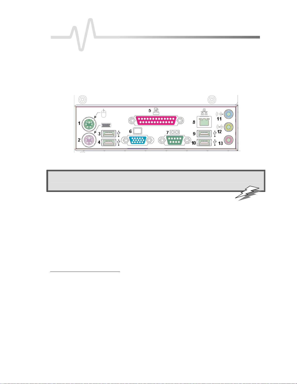
You can fully control your instrument remotely by using either the optional GPIB (General Purpose Interface
Bus) port, if available, or the LAN communication port on the scope's I/O panel, shown below (8). The only
actions for which you must use the front panel controls are to power up the scope and to set remote control
addresses.
Typical I/O panel, including the LAN port (8) used for remote control
: Use the instrument's Remote Control Assista nt to monitor all your remote control
TTIIPP:
operations. See the COMM_HELP command in Part Two of this manual.”
ST ANDARDS
LeCroy’s remote control commands conform to the GPIB IEEE 488.2
extension of the IEEE 488.1 standard, which deals mainly with electrical and mechanical issues.
*
standard. This may be considered an
COMPATIBILITY WITH OTHER LECROY SCOPES
Throughout LeCroy's history, the company has striven to maximize compatibility. This policy continues to
operate. But the X-Stream DSOs introduce a completely new philosophy in scope communication, enabling the
scopes to control powerful proprietary programs within the instrument and within the processing chain. You
may find that a few “GPIB” commands, used for the earlier scopes, do not work on X-Stream scopes. The
solution is to use the new Automation commands, which are described in Chapter 6. It is easy to integrate these
commands into a GPIB program, using the command VBS. But you should find that for the most frequently
used commands and queries, existing scopes and X-Stream scopes are compatible, apart from a few details.
*ANSI/IEEE Std. 488.2–1987, IEEE Standard Codes, Formats, Protocols, and Common Commands. The Institute of Electrical and Electronics Engineers, Inc., 345
East 47th Street, New York, NY 10017 USA
WM-RCM-E Rev C ISSUED: May 2004 5
Page 12

P ART O NE: ABOUT REMOTE CONTROL
PROGRAM MESSAGES
You control the oscilloscope remotely using program messages that consist of one or more commands or
queries. The program messages you send from the external controller to the X-Stream oscilloscope must
conform to precise format structures. The oscilloscope will execute all program messages sent in the correct
form, but will ignore those with errors.
You can use uppercase or lowercase characters, or both, in program messages; the scope does not distinguish
between them. But the MESSAGE command can faithfully transmit strings containing both lowercase and
uppercase letters.
Warning or error messages are normally not reported unless the controller explicitly examines the relevant status
register, or if the status-enable registers have been set so that the controller can be interrupted when an error
occurs. If you connect an external monitor to the instrument’s LAN port, however, you will be able to observe
all your remote control transactions, including error messages, as they happen. See the command
COMM_HELP in Part Two, “Commands.”
Program messages are separated by semicolons ; and end in a terminator:
<command/query>;.........;<command/query> <terminator>.
The oscilloscope will not decode an incoming program message before receiving its terminator. The exception is
when the program message is longer than the 256 byte input buffer; then the oscilloscope will start analyzing the
message when the buffer is full. Commands and queries are executed in the order in which they are transmitted.
In GPIB mode, the following are valid terminators:
<NL> New Line character (i.e., the ASCII new-line character, whose decimal value is 10)
<NL><EOI> New Line character with a simultaneous <EOI> signal
<EOI><EOI> Signal together with the last character of the program message
The <NL> <EOI> terminator is always used in response messages sent by the oscilloscope to the controller.
NNOOTTEE:
be set with a special call to the GPIB interface driver. Refer to the GPIB
interface manufacturer’s manual and support programs.
COMMANDS AND QUERIES
Program messages are made up of one or more commands or queries. While the command directs the
oscilloscope to change its state (for example, its timebase or vertical sensitivity) the query asks the oscilloscope
about that state. Very often, you will use the same characters for a command and a query, the query being
identified by a ? after the last character.
For example, to change the timebase to 2 ms/div, send this command to the oscilloscope:
TIME_DIV 2 M
Or, to ask the oscilloscope about its timebase, send this query: TIME_DIV?
: The <EOI> signal is a dedicated GPIB interface line, which can
6 ISSUED: May 2004 WM-RCM-E Rev C
Page 13

C HAPTER O NE:
Overview
A query causes the oscilloscope to send a response message. The control program should read this message with
a ‘read’ instruction to the GPIB or LAN interface of the controller.
The response message to the above query might be: TIME_DIV 10 NS
The portion of the query preceding the question mark is repeated as part of the response message. If desired,
this text can be suppressed with the command: COMM_HEADER.
Depending on the state of the oscilloscope and the computation to be done, several seconds may pass before a
response is received. Command interpretation does not have priority over other oscilloscope activities.
The general form of a command or a query consists of a command header, <header>, optionally followed by
one or several parameters, <data>, separated by commas:
<header>[?] <data>,...,<data>
The notation [?] shows that the question mark is optional (turning the command into a query).
There is a space between the header and the first parameter.
Use commas between parameters.
The terminator is not shown because usually it is automatically added by the interface driver routine writing to
GPIB.
: The response to a query can be a useful
TTIIPP:
way of generating a command that is known to
be correct, and the response can be copied
straight into your program.
Following are examples of how program messages are made up of commands and queries.
GRID DUAL This program message consists of a single command that instructs the oscilloscope to display a
dual grid.
BUZZ BEEP; DISPLAY OFF; DATE? This program message consists of two commands, followed by a
query. They instruct the oscilloscope to beep once, turn off the display, and then ask for the current date. Again,
the terminator is not shown.
DATE 15,JAN,1993,13,21,16 This command instructs the oscilloscope to set its date and time to 15 JAN 1993,
13:21:16. The command header DATE indicates the action, the 6 data values specify it in detail.
WM-RCM-E Rev C ISSUED: May 2004 7
: Set the controller I/O timeout conditions
TTIIPP:
to three or more seconds to give the scope time
to respond. An incorrect query will not get a
response; and, if Remote Control Assistant is
enabled, a beep will sound.
Page 14

P ART O NE: ABOUT REMOTE CONTROL
HEADERS
The header is the mnemonic form of the operation to be performed by the oscilloscope. Most command and
query headers have a long form, which allows them to be read more easily by people, and a short form for better
transfer and decoding speed. The two are fully equivalent and you can use them interchangeably. For example,
TRIG_MODE AUTO and TRMD AUTO are two separate but equivalent commands for switching to the
automatic trigger mode.
Some command or query mnemonics are imposed by the IEEE 488.2 standard. They are standardized so that
different oscilloscopes will present the same programming interface for similar functions. All these mnemonics
begin with an asterisk *. For example, the command *RST is the IEEE 488.2 imposed mnemonic for resetting
the oscilloscope, whereas *TST? instructs the oscilloscope to perform an internal self-test and report the
outcome.
HEADER PATHS
Certain commands or queries apply to a subsection of the oscilloscope; for example, a single input channel or a
trace on the display. In such cases, you must prefix the header by a path name that indicates the channel or trace
to which the command applies. The header path normally consists of a two-letter path name followed by a
colon : immediately preceding the command header. One of the waveform traces can usually be specified in the
header path:
Header Path Name Waveform Trace
C1, C2 Channels 1 and 2
C3, C4 Channels 3 and 4 (on four-channel models)
M1, M2, M3, M4 Memories 1, 2, and 3 and 4
F1, 2, F3, F4, F5, F6, F7, F8
TA, TB, TC, TD
EX, EX10, EX5 External trigger
LINE LINE source for trigger
Example: C1:OFST -300 MV Command to set the offset of Channel 1 to -300 mV.
You need only specify a header path once. Subsequent commands with header destinations not indicated are
assumed to refer to the last defined path. For example, the queries C2:VDIV?; C2:OFST? ask: What is the vertical
sensitivity and the offset of channel 2? While the queries C2:VDIV?; OFST? ask exactly the same questions
without repeating the path.
Traces F1 through F8
Equivalent to F1 through F4, for backward
compatibility with other LeCroy DSOs.
8 ISSUED: May 2004 WM-RCM-E Rev C
Page 15

C HAPTER O NE:
Overview
NNOOTTEE:
response from the scope uses the new label; for example, it substitutes
F3 for TC.
DATA
Whenever a command or query uses additional data values, the values are expressed as ASCII characters. There
is a single exception: the transfer of waveforms with the command/query WAVEFORM, where the waveform
can be expressed as a sequence of binary data values. See Chapter 4, “Wave f o r m Structu r e.” ASCII data can
have the form of character, numeric, string, or block data.
CHARACTER DATA
These are simple words or abbreviations to indicate a specific action.
Example: F3:TRA ON
In this example, the data value ON commands the trace F3 to be turned on (the data value OFF will have the
opposite effect).
However, this can become more complex. In some commands, where you can specify as many as a dozen
different parameters, or where not all the parameters are applicable at the same time, the format requires pairs
of data values. The first value names the parameter to be modified, while the second gives its value. Only those
parameter pairs that are to be changed need to be indicated.
Example: HARDCOPY_SETUP DEV,EPSON,PORT,GPIB
In this example, two pairs of parameters have been used. The first specifies the device as an EPSON (or
compatible) printer, while the second indicates the GPIB port. While the command HARDCOPY_SETUP
allows many more parameters, either they are not relevant for printers or they are left unchanged.
: If you use one of the older trace labels, for example "TC", any
NUMERIC DATA
The numeric data type is used to enter quantitative information. Numbers can be entered as integers or
fractions, or in exponential representation:
F1:VPOS -5 Move the display of Trace A downward by five divisions.
C2:OFST 3.56 Set the DC offset of Channel 2 to 3.56 V.
TDIV 5.0E-6 Adjust the timebase to 5 µsec/div.
Example: There are many ways of setting the timebase of the oscilloscope to 5 µsec/div:
TDIV 5E-6 Exponential notation, without any suffix.
TDIV 5 US
WM-RCM-E Rev C ISSUED: May 2004 9
Suffix multiplier U for 1E−6, with the (optional) suffix S for
seconds, or TDIV 5000 NS or TDIV 5000E-3 US
Page 16

P ART O NE: ABOUT REMOTE CONTROL
You can follow numeric values with multipliers and units to modify the value of the numerical expression. The
following mnemonics are recognized:
Multiplier Exp. Note. Suffix Multiplier Exp. Note. Suffix
EX 1E18 Exa- PE 1E15 Peta-
T 1E12 Tera- G 1E9 Giga-
MA 1E6 Mega- K 1E3 kilo-
M
N
F
STRING DA TA
This data type enables you to transfer a (long) string of characters as a single parameter. Simply enclose any
sequence of ASCII characters between single or double quotation marks:
MESSAGE ‘Connect probe to point J3’
The oscilloscope displays this message in the Message field above the grid.
BLOCK DATA
These are binary data values coded in hexadecimal ASCII: four-bit nibbles translated into the digits 0 through 9
or A through F, and transmitted as ASCII characters. They are used only for the transfer of waveforms from the
oscilloscope to the controller (WAVEFORM) and for instrument panel setups (PANEL_SETUP).
RESPONSE MESSAGES
The oscilloscope sends a response message to the controller in answer to a query. The format of such messages
is the same as that of program messages: individual responses in the format of commands, separated by
semicolons ; and ending in terminators. These messages can be sent back to the oscilloscope in the form in
which they were received, to be accepted as valid commands. In GPIB response messages, the <NL> <EOI>
terminator is always used.
Example: The controller sends the program message:
TIME_DIV?;TRIG_MODE NORM;C1:COUPLING? (terminator not shown).
1E−3
1E−9
1E−15
milli- U
nano- PI
femto- A
1E−6
1E−12
1E−18
micro-
pico-
atto-
The oscilloscope might respond to this with:
TIME_DIV 50 NS;C1:COUPLING D50 (terminator not shown).
The response message refers only to the queries: TRIG_MODE is left out. If this response is sent back to the
oscilloscope, it is a valid program message for setting its timebase to 50 ns/div and the input coupling of
Channel 1 to 50 Ω.
10 ISSUED: May 2004 WM-RCM-E Rev C
Page 17

C HAPTER O NE:
Whenever you expect a response from the oscilloscope, you must have the control program instruct the GPIB
or LAN interface to read from the oscilloscope. If the controller sends another program message without
reading the response to the previous one, the response message in the output buffer of the oscilloscope will be
discarded. The oscilloscope keeps to stricter rules for response messages than for acceptance of program
messages. While you can send program messages from the controller in uppercase or lowercase characters,
response messages are always returned in uppercase. Program messages may contain extraneous spaces or tabs
(white space), but response messages will not. And while program messages may contain a mixture of short and
long command or query headers, response messages always use short headers by default.
However, you can use the command COMM_HEADER to force the oscilloscope to use long headers, or none
at all. If the response header is omitted, the response transfer time will be minimized. But the response will not
be able to be sent back to the oscilloscope. Suffix units are also suppressed in the response. An advantage of
headerless operation is the ease with which programs can use the data, because they do not have to find and
remove the headers. But C1:PAVA? ALL will return a string like this - AMPL,292.3E-3,OK,DLY,-2.333E6,OK,FALL,95.121E-9,OK,MEAN,66E-6,OK,PER,332.8E-9,OK,PKPK,308E-3,OK,RISE,92.346E9,OK,RMS,106.1E-3,OK,SDEV,106.1E-3,OK,WID,166.3E-9,OK, even with CHDR OFF, because only the
header is removed. All other alphabetic information is always transmitted.
If you were to set the trigger slope of Channel 1 to negative, the query C1:TRSL? might yield the following
responses:
C1:TRIG_SLOPE NEG header format: long
C1:TRSL NEG header format: short
NEG header format: off
Overview
: Waveforms you obtain from the
TTIIPP:
oscilloscope using the query WAVEFORM?
are a special kind of response message.
Control their exact format by using the
COMM_FORMAT and COMM_ORDER
commands.
§ § §
WM-RCM-E Rev C ISSUED: May 2004 11
Page 18

C HAPTER T WO: Control by GPIB
In this chapter, see how to
¾ Address your X-Stream scope for GPIB
¾ Configure GPIB software
¾ Enable remote and local control
¾ Make transfers of data
¾ Make service requests
¾ Poll your X-Stream scope
¾ Set timing and synchronization
12 ISSUED: May 2004 WM-RCM-E Rev C
Page 19

C HAPTER TWO
Control by GPIB
Talk, Listen, or Control
You can control your X-Stream DSO remotely, using the General Purpose Interface Bus (GPIB). GPIB is
similar to a standard computer bus. But while the computer interconnects circuit cards by means of a
backplane bus, the GPIB interconnects independent devices (oscilloscopes and computers, for example) by
means of a cable bus. GPIB also carries both program and interface messages.
Program messages, often called device dependent messages, contain programming instructions, measurement
results, oscilloscope status and waveform data.
Interface messages manage the bus itself. They perform functions such as initialization, addressing and
“unaddressing” of devices, and the setting of remote and local modes.
On the one hand, devices connected by GPIB to your X-Stream DSO can be listeners, talkers, or controllers. A
talker sends program messages to one or more listeners, while a controller manages the flow of information on
the bus by sending interface messages to the devices. The host computer must be able to play all three roles.
For details of how the controller configures the GPIB for specific functions, refer to the GPIB interface
manufacturer’s manual.
On the other hand, the X-Stream DSO can be a talker or listener, but
Much of the material in this chapter is general to all GPIB systems, but where detailed instructions and
program fragments are provided in this manual, they are based on National Instruments hardware and
software, and on some form of BASIC language. Where INCLUDES are mentioned, this points to the need to
couple the programming language to the GPIB by including some drivers. The National Instruments manuals
explain this. Variables ending with % are integers, and variables ending with $ are strings, in accordance with
the practice in some BASIC languages. The entire system is of course compatible with any hardware and
software based on IEEE-488.2, and any programming language can be used if it can be linked to GPIB.
WM-RCM-E Rev C ISSUED: May 2004 13
NOT a controller.
Page 20

P ART O NE: ABOUT REMOTE CONTROL
INTERFACE
X-Stream DSO interface capabilities include the following IEEE 488.1 definitions:
AH1 Complete Acceptor Handshake DC1 Complete Device Clear Function
SH1 Complete Source Handshake DT1 Complete Device Trigger
L4 Partial Listener Function PP1 Parallel Polling: remote configurable
T5 Complete Talker Function C0 No Controller Functions
SR1 Complete Service Request Function E2 Tri-state Drivers
RL1 Complete Remote/Local Function
ADDRESS
Every device on the GPIB has an address. To address the X-Stream DSO, set the remote control port to GPIB
by means of the scope’s front panel UTILITIES button and on-screen menus.
If you address the X-Stream DSO to talk, it will remain in that state until it receives a universal untalk
command (UNT), its own listen address (MLA), or another oscilloscope’s talk address.
If you address the X-Stream DSO to listen, it will remain configured to listen until a universal unlisten
command (UNL), or its own talker address (MTA), is received.
To avoid conflicts, use the general Unlisten and Untalk commands before setting up the talker and listener
states.
The following characters are used in GPIB to control talking and listening:
ASCII 63 = ? General Unlisten
ASCII 95 = _ General Untalk
ASCII 32 = Space Base Listen Address
ASCII 64 = @ Base Talk Address
14 ISSUED: May 2004 WM-RCM-E Rev C
Page 21

C HAPTER T WO:
To make an actual talk address and listen address, we have to add the GPIB address to the ASCII values of the
base characters, to give the ASCII value of the new character. So a string of these commands looks like a
random set of characters. Using named variables makes programs easier to understand. For example, if we
have a DSO at GPIB address 4, and a PC at address 4, we construct the command strings as follows, for use
later in the program.
UnListen$ = Chr$ (63) : UnTalk$ = Chr$(95)
BaseListen% = 32 : BaseTalk% = 64 : DSOAddress% = 4
DSOListen$ = Chr$ (BaseListen% + DSOAddress%)
DSOTalk$ = Chr$ (BaseTalk% + DSOAddress%)
If the PC is at address 0, we can also write
PCTalk$ = Chr$ (BaseTalk%) : PCListen$ = Chr$(BaseListen%)
Finally:
DSOListenPCTalk$ = UnListen$ + UnTalk$ + PCTalk$ + DSOListen$
DSOTalkPCListen$ = UnListen$ + UnTalk$ + PCListen$ + DSOTalk$
These last two strings, once defined, can be used in programs for sending to the DSO.
GPIB SIGNALS
The GPIB system consists of 16 signal lines and eight ground or shield lines. The signal lines are divided into
three groups:
Control by GPIB
Data Lines: These eight lines, usually called DIO1 through DIO8, carry both program and interface messages.
Most of the messages use the 7-bit ASCII code, in which case DIO8 is unused.
Handshake Lines: These three lines control the transfer of message bytes between devices. The process is
called a three-wire interlocked handshake, and it guarantees that the message bytes on the data lines are sent
and received without transmission error.
Interface Management Lines: These five lines manage the flow of information across the interface:
• ATN (ATteNtion): The controller drives the ATN line true when it uses the data lines to send
interface messages such as talk and listen addresses or a device clear (DCL) message. When ATN is
false, the bus is in data mode for the transfer of program messages from talkers to listeners.
• IFC (InterFace Clear): The controller sets the IFC line true to initialize the bus.
• REN (Remote ENable): The controller uses this line to place devices in remote or local program
mode.
• SRQ (Service ReQuest): Any device can drive the SRQ line true to asynchronously request service
from the controller. This is the equivalent of a single interrupt line on a computer bus.
WM-RCM-E Rev C ISSUED: May 2004 15
Page 22

P ART O NE: ABOUT REMOTE CONTROL
• EOI (End Or Identify): This line has two purposes: The talker uses it to mark the end of a message
string. The controller uses it to tell devices to identify their response in a parallel poll (discussed later
in this section).
I/O BUFFERS
The oscilloscope has 256-byte input and output buffers. An incoming program message is not decoded before
a message terminator has been received. However, if the input buffer becomes full (because the program
message is longer than the buffer), the oscilloscope starts analyzing the message. In this case, data transmission
is temporarily halted, and the controller may generate a timeout if the limit was set too low.
USE IEEE 488.1 STANDARD MESSAGES
The IEEE 488.1 standard specifies not only the mechanical and electrical aspects of the GPIB, but also the
low-level transfer protocol. For instance, it defines how a controller addresses devices, turns them into talkers
or listeners, resets them, or puts them in the remote state. Such interface messages are executed with the
interface management lines of the GPIB, usually with ATN true.
All these messages except GET are executed immediately upon receipt.
The command list in Part Two of this manual does not contain a command for clearing the input or output
buffers or for setting the oscilloscope to the remote state.
NOTE: In addition to the IEEE 488.1 interface
message standards, the IEEE 488.2 standard
specifies certain standardized program messages,
i.e., command headers. They are identified with a
leading asterisk * and are listed in the System
Commands section.
This is because such commands are already specified as IEEE 488.1 standard messages. Refer to the GPIB
interface manual of the host controller as well as to its support programs, which should contain special calls for
the execution of these messages.
The following description covers those IEEE 488.1 standard messages that go beyond mere reconfiguration of
the bus and that have an effect on X-Stream DSO operation.
16 ISSUED: May 2004 WM-RCM-E Rev C
Page 23

C HAPTER T WO:
DEVICE CLEAR
In response to a universal Device CLear (DCL) or a Selected Device Clear message (SDC), the X-Stream DSO
clears the input or output buffers, cancels the interpretation of the current command (if any) and clears
pending commands. However, status registers and status-enable registers are not cleared. Although DCL will
have an immediate effect, it can take several seconds to execute if the oscilloscope is busy.
GROUP EXECUTE TRIGGER
The Group Execute Trigger message (GET) causes the X-Stream DSO to arm the trigger system, and is
functionally identical to the *TRG command.
REMOTE ENABLE
X-Stream DSOs do not lock out any local controls when placed in the remote state, or in RWLS. It always
accepts remote as well as local control inputs (unless you turn off remote control capability in UtilitiesÆ
Remote.)
INTERFACE CLEAR
The InterFace Clear message (IFC) initializes the GPIB but has no effect on the operation of the
X-Stream DSO.
Control by GPIB
NNOOTTEE:
: To illustrate the GPIB programming concepts, a number of examples are included here,
written in a similar way to BASIC. It is assumed that the controller is IBM-PC compatible, and that it
is equipped with a National Instruments GPIB interface card. Nevertheless, GPIB programming with
other languages such as C or Pascal is quite similar. If you’re using another type of computer or
GPIB interface, refer to the interface manual for installation procedures and subroutine calls.
This procedure refers to the installation and configuration of a GPIB card under the DOS operating
system. More recent operating systems (Windows 95, 98, ME, NT, 2000, XP, etc) generally use ‘Plug
‘n’ Play’ GPIB drivers, which are configured using an icon in the control panel.
CONFIGURE THE GPIB DRIVER SOFTWARE
Verify that the GPIB interface is properly installed in the computer. If it is not, follow the interface
manufacturer’s installation instructions. In the case of the National Instruments interface, it is possible to
modify the base I/O address of the board, the DMA channel number, and the interrupt line setting using
switches and jumpers. In the program examples below, default positions are assumed.
Connect the X-Stream DSO to the computer with a GPIB interface cable.
Set the GPIB address to the required value. The program examples assume a setting of 4.
WM-RCM-E Rev C ISSUED: May 2004 17
Page 24

P ART O NE: ABOUT REMOTE CONTROL
The host computer requires an interface driver that handles the transactions between the operator’s programs
and the interface board.
In the case of the National Instruments interface, the installation procedure will:
• Copy the GPIB handler GPIB.COM into the boot directory.
• Modify the DOS system configuration file CONFIG.SYS to declare the presence of the GPIB handler.
• Create a sub-directory called GPIB-PC, and install in GPIB-PC a number of files and programs useful for
testing and reconfiguring the system and for writing user programs.
The following files in the sub-directory GPIB-PC are particularly useful:
IBIC.EXE allows interactive control of the GPIB by means of functions entered at the keyboard. Use of this
program is highly recommended to anyone unfamiliar with GPIB programming or with the X-Stream DSO’s
remote commands.
IBCONF.EXE is an interactive program that allows inspection or modification of the current settings of the
GPIB handler. To run IBCONF.EXE or a later program version, refer to the National Instruments manual.
NNOOTTEE:
GPIB driver GPIB.COM is in its default state, i.e., that you have not modified it with IBCONF.EXE.
This means that the interface board can be referred to by the symbolic name ‘GPIB0’ and that devices
on the GPIB bus with addresses between 1 and 16 can be called by the symbolic names ‘DEV1’ to
‘DEV16’. If you have a National Instruments PC2 interface card rather than PC2A, you must run
IBCONF to declare the presence of this card rather than the default PC2A. Later boards from
National Instruments, and boards from other vendors, will require their own software, though NI has
achieved good compatibility with its earlier systems, and older software will often work with newer
boards.
: In the program examples in this section, it is assumed that the National Instruments (NI)
18 ISSUED: May 2004 WM-RCM-E Rev C
Page 25

C HAPTER T WO:
MAKE SIMPLE TRANSFERS
For a large number of remote control operations, it is sufficient to use just three different subroutines
(IBFIND, IBRD and IBWRT) provided by National Instruments. The following complete program reads the
timebase setting of the X-Stream DSO and displays it on the terminal:
Control by GPIB
GPIB:
Find: DEV$ = “DEV4” ‘ Because the DSO has been set at
CALL IBFIND (DEV$, SCOPE%) ‘ Find the DSO: label it “SCOPE%”.
Send: CMD$ = “TDIV?” ‘ Make a query string about the
CALL IBWRT (SCOPE%, CMD$) ‘ Send the string to the DSO.
Read: CALL IBRD (SCOPE%, RD$) ‘ Read the response from the DSO.
PRINT RD$ ‘ Print the response string.
END
Explanation
GPIB: This line or lines must hold the link between the programming language and the National Instruments
GPIB functions and drivers.
Find: Open the device DEV4 and associate with it the descriptor SCOPE%. All I/O calls after that will refer
to SCOPE%. The default configuration of the GPIB handler recognizes DEV4 and associates with it a device
with the GPIB address 4.
Send: Prepare the command string TDIV? and transfer it to the oscilloscope. The command instructs the
oscilloscope to respond with the current setting of the timebase.
Read: Read the response of the oscilloscope and place it into the character string RD$.
This line holds the INCLUDE for the GPIB routines
address 4.
time base speed.
WM-RCM-E Rev C ISSUED: May 2004 19
Page 26

P ART O NE: ABOUT REMOTE CONTROL
When running this sample program, the X-Stream DSO will automatically be set to the remote state when
IBWRT is executed, and will remain in that state. Here is a slightly modified version of the sample program
that checks if any error occurred during GPIB operation:
GPIB: ‘ This line should hold the INCLUDE for the GPIB routines
Address: DEV$ = “DEV4”
Find: CALL IBFIND (DEV$, SCOPE%) ‘ Find the DSO.
Send: CMD$ = “TDIV?” ‘ Time base query
CALL IBWRT (SCOPE%, CMD$) ‘ Send the string to the DSO.
ErrorS: IF IBSTA% < 0 THEN PRINT “WRITE ERROR =” ; IBERR% : END
Read: CALL IBRD (SCOPE%, RD$) ‘ Try to read a string from the
ErrorR: IF IBSTA% < 0 THEN PRINT “READ ERROR =” ; IBERR% : END
PRINT RD$
190 END
The GPIB status word IBSTA%, the GPIB error variable IBERR% and the count variable IBCNT% are
defined by the GPIB handler and are updated with every GPIB function call. IBSTA% is negative if there is an
error, while IBERR% shows what type of error has occurred. IBCNT% is the number of bytes transferred.
Refer to the National Instruments manual for details. The sample program above would report an error if the
GPIB address of the oscilloscope was set to a value other then 4. When you are sending remote commands to
the DSO, the IBSTA% and IBERR% don’t necessarily indicate that the scope accepted the string, but merely
that the string was correctly transmitted to the DSO to interpret. To ensure that commands were valid, and
weren’t rejected by the DSO, use the Remote Control Assistant.
DSO.
20 ISSUED: May 2004 WM-RCM-E Rev C
Page 27

C HAPTER T WO:
USE ADDITIONAL DRIVER CALLS
IBLOC is used to execute the IEEE 488.1 standard message Go To Local (GTL); i.e., it returns the
oscilloscope to the local state. The programming example above illustrates its use.
IBCLR executes the IEEE 488.1 standard message Selected Device Clear (SDC).
IBRDF and IBWRTF, respectively, allow data to be read from GPIB to a file, and written from a file to GPIB.
Transferring data directly to or from a storage device does not limit the size of the data block, but may be
slower than transferring to the computer memory.
IBRDI and IBWRTI allow data to be read from GPIB to an integer array, and written from integer array to
GPIB. Since the integer array allows storage of up to 64 kilobytes (in BASIC), IBRDI and IBWRTI should be
used for the transfer of large data blocks to the computer memory, rather than IBRD or IBWRT, which are
limited to 256 bytes by the BASIC string length. Note that IBRDI and IBWRTI only exist for BASIC, since for
more modern programming languages, such as C, the functions called IBRD and IBWRT are far less limited in
data block size.
IBTMO can be used to change the timeout value during program execution. The default value of the GPIB
driver is 10 seconds — for example, if the oscilloscope does not respond to an IBRD call, IBRD will return
with an error after the specified time.
IBTRG executes the IEEE 488.1 standard message Group Execute Trigger (GET), which causes the X-Stream
DSO to arm the trigger system.
Control by GPIB
National Instruments supplies a number of additional function calls. In particular, it is possible to use the socalled board level calls, which allow a very detailed control of the GPIB.
NOTE: The SRQ bit is latched until the controller reads the STatus Byte Register (STB). The action
of reading the STB with the command *STB? clears the register contents except the MAV bit (bit 4)
until a new event occurs. Service requesting can be disabled by clearing the SRE register with the
*SRE 0 command.
WM-RCM-E Rev C ISSUED: May 2004 21
Page 28

P ART O NE: ABOUT REMOTE CONTROL
MAKE SERVICE REQUESTS
When an X-Stream DSO is used in a remote application, events often occur asynchronously, i.e., at times that
are unpredictable for the host computer. The most common example of this is a trigger wait after the
oscilloscope is armed: the controller must wait until the acquisition is finished before it can read the acquired
waveform. The simplest way of checking if a certain event has occurred is by either continuously or
periodically reading the status bit associated with it until the required transition is detected. Continuous status
bit polling is described in more detail below. For a complete explanation of status bits, refer to Chapter 5.
Perhaps a more efficient way of detecting events occurring in the oscilloscope is the use of the Service
ReQuest (SRQ). This GPIB interrupt line can be used to interrupt program execution in the controller. The
controller can then execute other programs while waiting for the oscilloscope. Unfortunately, not all interface
manufacturers support the programming of interrupt service routines. In particular, National Instruments
supports only the SRQ bit within the ISTA% status word. This requires you to continuously or periodically
check this word, either explicitly or with the function call IBWAIT. In the absence of real interrupt service
routines, the use of SRQ may not be very advantageous.
In the default state, after power-on, the Service ReQuest is disabled. You enable SRQ by setting the Service
Request Enable register with the command “*SRE” and by specifying which event should generate an SRQ.
The X-Stream DSO will interrupt the controller as soon as the selected event(s) occur by asserting the SRQ
interface line. If several devices are connected to the GPIB, you may be required to identify which oscilloscope
caused the interrupt by serial polling the various devices.
Example: To assert SRQ in response to “new signal acquired.” This event is tracked by the INR register,
which is reflected in the SRE register as the INB summary bit in position 0. Since bit position 0 has the value 1,
the command *SRE 1 enables the generation of SRQ whenever the INB summary bit is set.
In addition, the events of the INR register that may be summarized in the INB bit must be specified. The
event “new signal acquired” corresponds to INE bit 0 (value 1) while the event “return-to-local” is assigned to
INE bit 2 (value 4). The total sum is 1 + 4 = 5. Thus the command INE 5 is needed:
CMD$ = “INE 5 ; *SRE 1”
CALL IBWRT (SCOPE%, CMD$)
22 ISSUED: May 2004 WM-RCM-E Rev C
Page 29

C HAPTER T WO:
Control by GPIB
Take Instrument Polls
You can regularly monitor state transitions within the oscilloscope by polling selected internal status registers.
There are four basic polling methods you can use to detect the occurrence of a given event: continuous, serial,
parallel, and *IST. By far the simplest of these is continuous polling. The others are appropriate only when
interrupt-service routines (servicing the SRQ line) are supported, or multiple devices on GPIB require constant
monitoring. To emphasize the differences between the methods, described below, the same example
(determining whether a new acquisition has taken place) is used in each case.
DO CONTINUOUS POLLING
A status register is continuously monitored until a transition is observed. This is the most straightforward
method for detecting state changes, but may not be practical in certain situations, especially with multiple
device configurations.
In the following example, the event “new signal acquired” is observed by continuously polling the INternal
state change Register (INR) until the corresponding bit (in this case bit 0, i.e., value 1) is non-zero, indicating
that a new waveform has been acquired. Reading INR clears this at the same time, so that there is no need for
an additional clearing action after a non-zero value has been detected. The command CHDR OFF instructs the
oscilloscope to omit any command headers when responding to a query, simplifying the decoding of the
response. The oscilloscope will then send “1” instead of “INR 1”:
CMD$ = “CHDR OFF”
CALL IBWRT (SCOPE%, CMD$)
MASK% = 1 ‘ New Signal Bit has value 1
DO
CMD$ = “INR?”
CALL IBWRT (SCOPE%, CMD$)
CALL IBRD (SCOPE%, RD$)
NEWSIG% = VAL (RD$) AND MASK%
LOOP UNTIL NEWSIG% = MASK%
WM-RCM-E Rev C ISSUED: May 2004 23
Page 30

P ART O NE: ABOUT REMOTE CONTROL
TAKE A SERIAL POLL
Serial polling takes place once the SRQ interrupt line has been asserted, and is only advantageous when you are
using several oscilloscopes at once. The controller finds which oscilloscope has generated the interrupt by
inspecting the SRQ bit in the STB register of each. Because the service request is based on an interrupt
mechanism, serial polling offers a reasonable compromise in terms of servicing speed in multiple-device
configurations.
In the following example, the command INE 1 enables the event “new signal acquired” to be reported in the
INR to the INB bit of the status byte STB. The command *SRE 1 enables the INB of the status byte to
generate an SRQ whenever it is set. The function call IBWAIT instructs the computer to wait until one of
three conditions occurs: &H8000 in the mask (MASK%) corresponds to a GPIB error, &H4000 to a timeout
error, and &H0800 to the detection of RQS (ReQuest for Service) generated by the SRQ bit.
Whenever IBWAIT detects RQS, it automatically performs a serial poll to find out which oscilloscope
generated the interrupt. It will only exit if there was a timeout or if the oscilloscope (SCOPE%) generated
SRQ. The additional function call IBRSP fetches the value of the status byte, which may be further interpreted.
For this to work properly, the value of “Disable Auto Serial Polling” must be set to “off” in the GPIB handler
(use IBCONF.EXE to check).
CMD$ = “*CLS ; INE 1;*SRE 1”
CALL IBWRT (SCOPE%, CMD$)
MASK% = &HC800
CALL IBWAIT (SCOPE%, MASK%)
IF (IBSTA% AND &HC000) <> 0 THEN PRINT “GPIB or Timeout Error” : STOP
CALL IBRSP (SCOPE%, SPR%)
PRINT “Status Byte =.”, SPR%
Board-level function calls can deal simultaneously with several oscilloscopes attached to the same interface
board. Refer to the National Instruments manual.
NOTE: After the serial poll is completed, the RQS bit in the STB status register is cleared. Note that
the other STB register bits remain set until they are cleared by means of a “*CLS” command or the
oscilloscope is reset. If these bits are not cleared, they cannot generate another interrupt
DO A PARALLEL POLL
Like serial polling, this is only useful when several oscilloscopes are connected. The controller simultaneously
reads the Individual STatus bit (IST) of all oscilloscopes to determine which one needs service. This method
allows up to eight different oscilloscopes to be polled at the same time.
When a parallel poll is initiated, each oscilloscope returns a status bit over one of the DIO data lines. Devices
may respond either individually, using a separate DIO line, or collectively on a single data line. Data-line
assignments are made by the controller using a Parallel Poll Configure (PPC) sequence.
.
24 ISSUED: May 2004 WM-RCM-E Rev C
Page 31

C HAPTER T WO:
Control by GPIB
In the following example, the command INE 1 enables the event “new signal acquired” in the INR to be
reported to the INB bit of the status byte STB. The PaRallel poll Enable register (PRE) determines which
events will be summarized in the IST status bit. The command *PRE 1 enables the INB bit to set the IST bit
whenever it is itself set. Once parallel polling has been established, the parallel-poll status is examined until a
change on data bus line DIO2 takes place.
Stage 1
1. Enable the INE and PRE registers
2. Configure the controller for parallel poll
3. Instruct the X-Stream DSO to respond on data line 2 (DIO2) with these commands:
CMD1$ = DSOListenPCTalk$ ‘ As defined earlier
CALL IBCMD (BRD0%, CMD1$)
CMD$ = “INE 1;*PRE 1”
CALL IBWRT (BRD0%, CMD$)
PPE$ = Chr$ (&H5) ‘ GPIB Parallel Poll Enable
MSA9$ = Chr$ (&H69) ‘ GPIB Secondary Address 9
CMD4$ = PPE$ + MSA9$ + UnListen$
CALL IBCMD (BRD0%, CMD4$)
Stage 2
4. Parallel poll the oscilloscope until DIO2 is set with these commands:
Do
CALL IBRPP (BRD0%, PPR%)
Loop Until (PPR% AND &H2) = 2
Stage 3
5. Disable parallel polling (hex 15) and clear the parallel poll register with these commands:
PPU$ = Chr$ (&H15) ‘ GPIB Parallel Poll
Unconfigure
CALL IBCMD (BRD0%, PPU$)
CALL IBCMD (BRD0%, CMD1$) ‘ As defined earlier
CMD$ = “*PRE 0” : CALL IBWRT(BRD0%,CMD$):
In the above example, board-level GPIB function calls are used. It is assumed that the controller (board) and
the X-Stream DSO (device) are located at addresses 0 and 4, respectively.
WM-RCM-E Rev C ISSUED: May 2004 25
Page 32

P ART O NE: ABOUT REMOTE CONTROL
The listener and talker addresses for the controller and the X-Stream DSO are:
LOGIC DEVICE LISTENER ADDRESS TALKER ADDRESS
External Controller 32 (ASCII<space>) 64 (ASCII @)
X-Stream DSO 32 + 4 = 36 (ASCII $) 64 + 4 = 68 (ASCII D)
PERFORM AN *IST POLL
You can also read the state of the Individual STatus bit (IST) returned in parallel polling by sending the *IST?
query. To enable this poll mode, you must initialize the X-Stream DSO as for parallel polling by writing into the
PRE register. Since *IST emulates parallel polling, apply this method wherever parallel polling is not supported
by the controller. In the following example, the command INE 1 enables the event “new signal acquired” in the
INR to be reported to the INB bit of the status byte STB. The command *PRE 1 enables the INB bit to set
the IST bit whenever it is set. The command CHDR OFF suppresses the command header in the
oscilloscope’s response, simplifying the interpretation. The status of the IST bit is then continuously monitored
until set by the oscilloscope:
CMD$ = “CHDR OFF; INE 1; *PRE 1”
CALL IBWRT (SCOPE%, CMD$)
DO
CMD$ = “*IST?”
CALL IBWRT (SCOPE%, CMD$)
CALL IBRD (SCOPE%, RD$)
LOOP UNTIL VAL (RD$) = 1
26 ISSUED: May 2004 WM-RCM-E Rev C
Page 33

C HAPTER T WO:
Control by GPIB
Timing and Synchronization
Depending on how your remote program is written, it may be affected by timing changes between different
DSO series, even between Waverunner DSOs and WavePro DSOs. In X-Stream DSOs, these effects may be
even more pronounced than in previous scopes, for several reasons. Firstly, X-Stream DSOs are faster than our
earlier scopes. Secondly, X-Stream DSOs support faster interfaces. That is, the standard network interface is
100Base-T instead of 10Base-T. Secondly, and more significantly, for the most part our earlier scope series
processed remote commands sequentially. That is, they would not start executing any command until execution
of the previous one had finished. This meant that many operations were automatically synchronous by default,
and remote control programs which did not use status bytes or *OPC?, may have worked "by luck." That is not
the case in X-Stream DSOs. Since they use multitasking , you must be much more diligent in programming.
Most timing and synchronization problems are related to changing acquisitions, or the completion of analysis
after an acquisition occurs. For example, if you change the offset of channel 1 while the scope is in Auto
trigger mode, and then you use the PAVA? query to read a parameter computed on channel 1, in the older
scopes, you would almost always get the results after the data has been acquired with the new offset. However,
in X-Stream DSOs, the processing is overlapped with the next acquisition and, as a consequence, the PAVA?
result may have come from the acquisition prior to the offset change.
There are several ways of ensuring that your program gives the correct results when controlling the scope
remotely. To simplify the synchronization issue, in most cases you can put the scope into single trigger mode.
Then you can use either the status registers available in the scope, or the *OPC? query and the WAIT
command to detect completion when the acquisition and any processing are done.
Note that when you arm the scope by sending the TRMD SINGLE command, the scope will automatically
perform any necessary calibrations before actually starting to acquire data. These calibrations may take several
seconds, so if you query the status immediately after sending TRMD SINGLE, you need to have the GPIB (or
remote) timeout set to be at least 10 seconds to prevent a timeout before getting the correct results.
Calibrations are performed if your program changes some control settings (e.g., volts/div, number of active
channels, etc.) or if the temperature of the scope has changed significantly. You can disable the calibrations by
sending the AUTO_CALIBRATE OFF command. However, the scope performance may be degraded if the
temperature changes and it does not get a chance to self calibrate. A calibration of the X-Stream DSO can be
"forced" by issuing a *CAL? command. This technique allows you to control the timing of calibrations so that
they will not interfere with the acquisition of important data.
One case when you may need to use "normal" or "auto" trigger mode is the accumulation of many acquisitions
for functions such as averaging or histogramming. In this case, it is best to stop the acquisitions, set up the
scope, and then set the trigger mode to NORMAL to acquire the data. (A possible alternative is to use
sequence mode. It is faster, but does require that you know how many acquisitions to accumulate. That number
can be specified and captured in sequence mode).
WM-RCM-E Rev C ISSUED: May 2004 27
Page 34

P ART O NE: ABOUT REMOTE CONTROL
STATUS REGISTERS
Status registers store a record of events and conditions that occur inside the DSO. Some of the events
recorded are: New data has been acquired; Processing has completed; Hardcopy has completed; An error has
occurred; etc. The programmer can use the registers to sense the condition of the instrument by polling them
until the desired status bit has been set. A status register can be polled by querying its associated remote
command (e.g., *STB, INR?, *ESR, etc.). Alternatively, with GPIB, the scope can request service from the
controller by using the mask registers to select the events of interest.
The following diagram (Figure 1) shows the steps necessary to acquire data using the status registers for
synchronization.
28 ISSUED: May 2004 WM-RCM-E Rev C
Page 35

C HAPTER T WO:
If the data have already been acquired and you want to do further analysis (math, parameters, cursors) on it,
you can proceed as shown in Figure 2:
Control by GPIB
For more details on Status registers, see Chapter 5.
SYNCHRONZING WITH *OPC? AND WAIT
The *OPC? query returns a 1 when the previous commands have finished. Therefore, you can use this query
with the WAIT command to synchronize the scope with your controller, using the steps shown in Figure 3
below. The WAIT command waits for the acquisition to complete, but it does not wait for the processing. The
WAIT command allows you to specify an optional timeout so that if the scope does not trigger, your program
will not hang. However, if you use the timeout, it is strongly advised to subsequently check the status registers
to ensure that the scope actually triggered and that any processing has completed.
WM-RCM-E Rev C ISSUED: May 2004 29
Page 36

P ART O NE: ABOUT REMOTE CONTROL
§ § §
30 ISSUED: May 2004 WM-RCM-E Rev C
Page 37

C HAPTER T WO:
BLANK PAGE
Control by GPIB
WM-RCM-E Rev C ISSUED: May 2004 31
Page 38

C HAPTER T HREE: Control by LAN
In this chapter, see how to
¾ Control X-Stream by LAN
¾ Simulate GPIB messages using LAN
32 ISSUED: May 2004 WM-RCM-E Rev C
Page 39

C HAPTER THREE
Control by LAN
Introduction
¾ The Ethernet connection (10Base-T and 100Base-T) allows you to control the instrument over a network,
or through a direct connection between the oscilloscope and a computer. The connection is made through
the Ethernet port located at the rear of the oscilloscope.
¾ This chapter introduces the basic capabilities for control of the instrument over the Ethernet interface.
This manual gives a complete description of the remote control commands. The commands apply to control
of the oscilloscope via Ethernet and GPIB.
Implementation Standard
1
To the greatest extent possible, these remote commands conform to the IEEE 488.2
considered an extension of the IEEE 488.1 standard, dealing mainly with electrical and mechanical issues.
When using LAN, the strings of data that are to be sent to the instrument must be preceded by the requisite
header.
Connections
The oscilloscope can be connected to the computer via Ethernet, using a TCP/IP network protocol.
standard, which may be
This connection can be made through a network (using a hub, switch, etc,) with a straight through network
cable, or between the oscilloscope’s Ethernet interface and a computer using a crossover network cable.
Connecting the Instrument to its Host
This section describes connecting the instrument to the host PC or network over the standard
10Base-T/100Base-T Ethernet. Windows NT and Windows 95 operating systems are supported.
1
ANSI/IEEE Std. 488.2–1987, IEEE Standard Codes, Formats, Protocols, and Common Commands. The Institute of Electrical and
Electronics Engineers Inc., 345 East 47th Street, New York, NY 10017, USA.
WM-RCM-E Rev C ISSUED: May 2004 33
Page 40

P ART O NE: ABOUT REMOTE CONTROL
Scope Rear Panel
The LAN connector is shown in the illustration above (item 8).
• Supports IEEE 802.3 Ethernet standards
• Supports 10Base-T and 100Base-T
Ethernet Connection
The instrument operates over a standard 10Base-T/100Base-T Ethernet connection. The instrument can be
plugged into a network or operated from a direct connection to a host computer. A different type of cable is
required for each of these connections. For a direct connection to the PC, a crossover cable is required,
whereas the network connection is made using a straight cable.
Headers for LAN Data Transfers
The format of the header sent before each data block, both to and from the instrument, is set out in the
following table:
Byte #
0 Operation
1 Header Version
2 Spare (reserved for future expansion)
3 Spare (reserved for future expansion)
4 Block Length, (bytes of data), MSB
5 Block Length (bytes of data)
6 Block Length (bytes of data)
7 Block Length, (bytes of data), LSB
Purpose
34 ISSUED: May 2004 WM-RCM-E Rev C
Page 41

C HAPTER T HREE:
Control by LAN
The ‘Operation’ bits and meanings are:
D7 D6 D5 D4 D3 D2 D1 D0
DATA REMOTE LOCKOUT CLEAR SRQ Reserved Reserved EOI
DATA
MNEMONIC PURPOSE
BIT
D7 DATA Data block (D0 indicates termination with/without EOI)
D6 REMOTE Remote Mode
D5 LOCKOUT Local Lockout (Lockout front-panel)
D4 CLEAR Device Clear (if sent with data, clear occurs before data block is passed to parser)
D3 SRQ SRQ (Device to PC only)
D2..D1 Reserved Reserved for future expansion
D0 EOI Block terminated in EOI
Logic "1" = use
Logic "0" = no EOI terminator
Note:
The following examples assume that the host PC operates from Windows™ 95. The
→ EOI terminator
connection procedure for Windows NT is similar.
WM-RCM-E Rev C ISSUED: May 2004 35
Page 42

P ART O NE: ABOUT REMOTE CONTROL
Manual Setting of LAN Address
If you do need to set an address for the instrument, go into Windows and perform the usual operations for
setting an address. Before establishing a direct connection between the oscilloscope and the host
computer, the PC must first be properly configured. A specific TCP/IP address must be assigned —
cannot
known as "static addressing." But this means that the PC
from a DHCP server. To set the host PC’s static address with Windows 95:
1. Select Start → Settings → Control Panel.
2. Double-click the Network icon in the Control Panel. A network dialog box similar to this one appears:
be set up to obtain its IP address
36 ISSUED: May 2004 WM-RCM-E Rev C
Page 43

C HAPTER T HREE:
3. If the TCP/IP protocol is not listed, you will have to add it. Follow your operating system user guide to
add the TCP/IP protocol and bind it to the Ethernet adapter.
Control by LAN
4. Double-click the
line. A dialog box similar to the one below appears. Select
5. If this has already been selected, the computer’s static address is set and nothing more needs to be done.
Cancel out of the TCP/IP and network dialog boxes, and close the control panel.
6. If the address has not already been selected, fill in the IP address and subnet mask as shown above. The
subnet mask for 172.25.x.x is 255.255.0.0. If the computer will not be plugged into a network, the above
WM-RCM-E Rev C ISSUED: May 2004 37
Page 44

P ART O NE: ABOUT REMOTE CONTROL
address (or almost any address within the chosen subnet) will suffice. The only address that will not work
is the same one as that of the oscilloscope to be controlled.
7. Now click
version, you may need to reboot the computer. If so, a dialog box should alert you to this.
Making Physical Connection
To make the physical connection between the oscilloscope and the host computer:
1. Connect the oscilloscope to the PC using a crossover cable (for direct connection).
2. Power the oscilloscope unit on.
Note:
If your PC does not have TCIP/IP, see your computer’s User’s Manual for installation
in the TCP/IP Properties dialog box. Depending on the operating system and
instructions.
Note:
If you are making connection using the VCIP protocol, use this syntax:
VICP::<scope’s IP address>
For example, VICP::172.28.15.16
Verifying Connection
The physical connection and the PC’s TCP/IP configuration can be verified using the “ping” command,
available on both Windows™ 95 and Windows™ NT with TCP/IP network protocol installed. In order to
check the network connection between the PC and the oscilloscope:
1. Start MS-DOS Prompt
2. Type ping <ip_address>, where <ip_address> is the static address assigned to the oscilloscope. The
Command Prompt window on the next page illustrates the result of a successful “ping,” with the Ethernet
connection shown established. The ping command has sent a message to the instrument and waited
for a response. If a timeout occurs, the IP address used for the destination (the oscilloscope) is
incorrect
or not within the subnet mask of the PC’s IP.
38 ISSUED: May 2004 WM-RCM-E Rev C
Page 45

C HAPTER T HREE:
Network Connection
Check with your network administrator before connecting the oscilloscope to a network. Incorrect addresses
on a network can cause both the network and the oscilloscope to behave strangely. However, a network
connection ought to be as simple as plugging the oscilloscope into the network. Proper connection can be verified by
following the verification instructions in the previous section.
Control by LAN
not
If you are concerned mainly with system throughput, network connection is
because the network traffic will slow down the oscilloscope’s data transfer rate.
recommended
Note: The default Gateway is assigned as "172.25.0.1". Unless your network has this Gateway
available, you must ensure that the computer and the oscilloscope are on the same subnet.
Changing IP Address Once the IP address is changed, the unit will no longer respond to the original address.
If the network settings are unknown or accidentally set to invalid values, they can be recovered by following the
procedure above.
WM-RCM-E Rev C ISSUED: May 2004 39
Page 46

P ART O NE: ABOUT REMOTE CONTROL
Introduction to Software Tools
The instrument software tools allow you to develop your own application specific programs quickly
and easily. These tools are based on
be found on the CD-ROM and on LeCroy’s Web site at http://www.lecroy.com/tm/library/software/
ActiveDSO™.
The files for all the software described here are to
.
ActiveDSO
Microsoft software tools, and makes programming within the Microsoft environment easier. ActiveDSO
simplifies the computer’s interface with the instrument, and simplifies programming within Visual C++, Visual
Basic, or any other ActiveX compatible applications. For example, Microsoft Excel can even be used to control
and retrieve data directly from the instrument. This tool becomes part of the target application and provides
seamless access to the full power of the instrument.
Based on Microsoft’s ActiveX control technology, ActiveDSO gives leverage to widely available
Using ActiveDSO
ActiveDSO is highly suitable for fast program development in the Microsoft environment. This
program is a control of ActiveX, the software technology developed by Microsoft as a subset of its
COM model.
ActiveDSO facilitates programming with the instrument by providing a ready interface between the instrument
and the host computer. Programs such as Visual C++, Visual Basic, or Visual Basic for Applications (VBA) can
be used under remote control without concern for interfacing complications. ActiveDSO acts as the key design
structure allowing effective integration of software from the different manufacturers supporting ActiveX
containment.
CONTROL INSTANTIA T ION
This ActiveX component can be instantiated more than once by using the Visual Basic function CreateObject.
Once the object is created, invoking the connection method will initialize it. ActiveDSO enables control of the
instrument from a variety of PC desktop applications. The complexities of programming with Ethernet are
fully encapsulated in this control. For example, with less than 10 lines of VBA code in an Excel macro the
spreadsheet can recover pre-scaled waveform data from the X-Stream DSO (see the on-line Excel example in
ActiveDSO).
ActiveDSO control can be used in two fundamental ways:
1. As a visible object embedded in an OLE automation compatible client (PowerPoint, for example) showing
a captured instrument display image. See the Embedded Control example below for more details.
2. As an invisible object accessed through a scripting language (VBA, for example) to remotely control the
instrument. See VBA example below for more details.
The ActiveDSO control may be embedded in any ActiveX containment-capable client, and may be used
manually without need of any programming or scripting.
Example:
waveform captured by the instrument can be easily imported into PowerPoint with just a few mouse clicks:
PowerPoint This example shows the control being embedded in a Microsoft PowerPoint slide. The
40 ISSUED: May 2004 WM-RCM-E Rev C
Page 47

C HAPTER T HREE:
1. Ensure that the ActiveDSO files from the CD-ROM are installed on the PC.
2. Verify that the PC and instrument are properly connected to the Ethernet.
3. Open a new blank presentation in PowerPoint.
Control by LAN
Note: This example assumes that PowerPoint 2002 is being used. Earlier (or Later) versions may not
behave in the same manner.
4. Select Insert, then Object, as shown here:
WM-RCM-E Rev C ISSUED: May 2004 41
Page 48

P ART O NE: ABOUT REMOTE CONTROL
5. From the pop-up window, select LeCroy ActiveDSO Control, as shown here:
42 ISSUED: May 2004 WM-RCM-E Rev C
Page 49

C HAPTER T HREE:
6. From the Edit menu, select LeCroy ActiveDSO Control Object, then Edit::
7. Right-click the object and select Make Connection.
8. Select Network TCP/IP connection, as shown here (“scope” = WaveMaster):
Control by LAN
WM-RCM-E Rev C ISSUED: May 2004 43
Page 50

P ART O NE: ABOUT REMOTE CONTROL
9. Enter the instrument’s IP address and click OK.
The address can also be specified in URL form, or 127.0.0.1 if you are running the controlling application
on the instrument.
44 ISSUED: May 2004 WM-RCM-E Rev C
Page 51

C HAPTER T HREE:
Control by LAN
10. Right-click the object again and select the Refresh Image menu item. A captured waveform will be
displayed similar to the one shown here:
Instrument’s captured waveform imported into PowerPoint
Once the ActiveDSO object has been properly set within the application, a macro script can be created,
utilizing an object method such as WriteString() to send DISP ON, C1:TRA ON, TRMD. Then RefreshImage()
method can be used to update the screen.
WM-RCM-E Rev C ISSUED: May 2004 45
Page 52

P ART O NE: ABOUT REMOTE CONTROL
Example:
VBA
VBA is the programming language built in to many of the more recent Windows applications. It is a subset of
Visual Basic that makes using OLE Automation Servers and ActiveX Controls very simple. The following VBA
subroutine demonstrates how easy it is to connect to an instrument and send remote commands to it.
_______________________________________________________
Sub LeCroyDSOTest()
Dim dso As Object
Set dso = CreateObject("LeCroy.ActiveDSO.1")
Call dso.AboutBox ‘ Present the control's About box
Call dso.MakeConnection("IP:172.25.1.2") ‘ Connect to the unit
Call dso.WriteString("C1:VDIV 2", 1) ‘ Setup C1 for 2 Volts/Div
Call dso.WriteString("TRMD AUTO", 1) ‘ Set the trigger mode to AUTO
End Sub
_____________________________________________________
To enter the VBA editor in members of the Microsoft Office suite:
1. Select Tools → Macro → Visual Basic Editor menu item.
2. When the VBA window appears, select the Insert → Module menu item.
3. Copy the above example into the editor window that appears.
To execute:
4. Position the text cursor within the subroutine.
5. Either select the Run → Run Sub/UserForm or press function key F5.
Note: For more information, see the ActiveDSO on-line Help. On-line Help contains VisualC++
examples, and explanations of ActiveDSO Methods and Properties.
ActiveDSO
This ActiveX
TM
control enables LeCroy oscilloscopes to be controlled by, and to exchange
data with, a variety of Windows applications that support the ActiveX standard. MS Office programs, Internet
Explorer, Visual Basic, Visual C++, Visual Java, and MATLAB (V5.3 and later) are a few of the many
applications that support ActiveX controls. ActiveDSO is available on CD-ROM or on the internet at
www.lecroy.com
•
With ActiveDSO you can develop your test program using standard GPIB commands. For easy integration
of your scope data with your Windows Application (through GPIB or Ethernet 10Base-T or 100Base-T),
ActiveDSO helps you with the following tasks:
• Generate a report by importing scope data right into Excel or Word.
46 ISSUED: May 2004 WM-RCM-E Rev C
Page 53

C HAPTER T HREE:
Control by LAN
• Archive measurement results on the fly in a Microsoft Access Database.
• Automate tests using Visual Basic, Java, C++, Excel (VBA).
• The ActiveDSO control hides the intricacies of programming and provides a simple and consistent
interface to the controlling application. With less than 10 lines of VBA (Visual Basic for Applications)
code in an Excel macro the spreadsheet can recover pre-scaled waveform data from a remote instrument.
• The ActiveDSO control can also be embedded visually in any OLE automation compatible client, and can
be used manually without any need for programming. It will run on any PC running Windows 95,
Windows 98, or Windows NT.
• There are two fundamental ways to use the control:
o As a visible object embedded in an OLE Automation compatible Client (PowerPoint for example)
showing a captured display image. See Embedded Control Example for more details.
o As an invisible object accessed via a scripting language (Visual Basic for Applications, for example) to
remotely control an instrument. See Accessing from VBA for more details.
• VBA (Visual Basic for Applications) is the programming language built into many of the more recent
Windows applications. It is a subset of Visual Basic that makes it very simple to utilize the services of
OLE Automation Servers and ActiveX Controls.
• The following VBA subroutine demonstrates how easy it is to connect to an instrument and send remote
commands to it.
Sub LeCroyDSOTest()
Dim o As Object
Set o = CreateObject("LeCroy.ActiveDSOCtrl.1")
Call o.AboutBox ' Present the control's About box
Call o.MakeConnection("IP: 172.28.11.26) 'Connect to device on LAN
Call o.WriteString("BUZZ BEEP", True) ' Make the DSO beep
End Sub
Example Syntax:
• Boolean controlName.WriteString
• The WriteString method has the following arguments.
Argument Description
• controlname The name of the ActiveDSO control object.
• textString String, Text string to send to the device.
• EOI Boolean, TRUE = terminate with EOI
WM-RCM-E Rev C ISSUED: May 2004 47
Page 54

P ART O NE: ABOUT REMOTE CONTROL
• Returns: True on success, False on failure.
• Remarks: This method sends a string command to the instrument.
• If EOI is set to TRUE, the device will start to interpret the command immediately. This is normally the
desired behavior.
• If EOI is set to FALSE, a command may be sent in several parts with the device starting to interpret the
command only when it receives the final part, which should have EOI set to TRUE.
§ § §
48 ISSUED: May 2004 WM-RCM-E Rev C
Page 55

C HAPTER T HREE:
BLANK PAGE
Control by LAN
WM-RCM-E Rev C ISSUED: May 2004 49
Page 56

C HAPTER F OUR: Understanding and Managing Waveforms
In this chapter, see how to
¾ Structure Waveforms
¾ Inspect waveform contents
¾ Transfer waveforms rapidly
50 ISSUED: May 2004 WM-RCM-E Rev C
Page 57

C HAPTER FOUR
Understanding and Managing Waveforms
Know Your Waveform
A waveform can be said to have two main parts. One is its basic data array: raw data values from the
oscilloscope’s ADCs (Analog-to-Digital Converters) obtained in the waveform’s capture. The other is the
description that accompanies this raw data: the vertical and horizontal scale or time of day, for example,
necessary for a full understanding of the information contained in the waveform. When these parts are
transmitted together, the descriptor comes first.
You can access this descriptive information by remote control using the INSPECT? query, which interprets it
in an easily understood ASCII text form. And you can rapidly transfer the waveform data using the
WAVEFORM? query. You can write it back into the oscilloscope with the WAVEFORM command.
Your instrument contains a data structure (template, see Appendix II) that provides a detailed description of
how waveform information is organized. Although a sample template is provided with this manual, we suggest
you use the TEMPLATE? query to access the instrument template in the oscilloscope itself (the template may
change as your oscilloscope’s firmware is enhanced).
Using the STORE and STORE_SETUP commands, you can also store waveforms in preformatted ASCII
output for popular spreadsheet and math processing packages.
LOGICAL DATA BLOCKS
Each of your waveforms will normally contain at least a waveform descriptor and data array block. However,
other blocks may also be present in more complex waveforms.
Waveform Descriptor block (WAVEDESC): This includes all the information necessary to reconstitute the
display of the waveform from the data, including: hardware settings at the time of acquisition, the exact time
of the event, kinds of processing performed, your oscilloscope name and serial number, the encoding format
used for the data blocks, and miscellaneous constants.
Sequence Acquisition Times block (TRIGTIME): This is needed for sequence mode acquisitions to
record the exact timing information for each segment. It contains the time of each trigger relative to the trigger
of the first segment, as well as the time of the first data point of each segment relative to its trigger.
Random Interleaved Sampling times block (RISTIME): This is required for RIS acquisitions to record the
exact timing information for each segment.
First Data Array block (SIMPLE or DATA_ARRAY_1): This is the basic integer data of the waveform. It
can be raw or corrected ADC data or the integer result of waveform processing.
WM-RCM-E Rev C ISSUED: May 2004 51
Page 58

P ART O NE: ABOUT REMOTE CONTROL
Second Data Array block (DATA_ARRAY_2): This is a second data array, needed to hold the results of
processing functions such as Extrema or FFT math functions:
EXTREMA FFT
NOTE: The instrument template
also describes an array named DUAL.
DATA_ARRAY_1 Roof trace Real part
DATA_ARRAY_2 Floor trace Imaginary part
INSPECT WAVEFORM CONTENTS
Use the INSPECT? query to examine the contents of your waveform. You can use it on both of the main
waveform parts. Its most basic form is: INSPECT? “name”, the template giving you the name of a descriptor
item or data block. You may use single quotation marks or double ones in the command (or none at all) but the
reply will always use double quotes. The answer is returned as a single string, but may cover many lines. Some
typical dialogue follows:
Question C1:INSPECT? “VERTICAL_OFFSET”
Response “VERTICAL_OFFSET: -4.0000e-002”
Question C1:INSPECT? “TRIGGER_TIME”
Response “TRIGGER_TIME: Date = APR 8, 2004, Time = 10:29: 0.311462573”
You can also use INSPECT? to provide a readable translation of the full waveform descriptor block using
INSPECT? “WAVEDESC”. Again, the template will give you the details for interpretation of each of the
parameters. Also use INSPECT? “SIMPLE” to examine the measured data values of a waveform. For example,
for an acquisition with 52 points:
INSPECT? “SIMPLE”
C1:INSP “
0.0005225 0.0006475 -0.00029 -0.000915 2.25001E-05 0.000835
0.0001475 -0.0013525 -0.00204 -4E-05 0.0011475 0.0011475
-0.000915 -0.00179 -0.0002275 0.0011475 0.001085 -0.00079
-0.00179 -0.0002275 0.00071 0.00096 -0.0003525 -0.00104
0.0002725 0.0007725 0.00071 -0.0003525 -0.00129 -0.0002275
0.0005225 0.00046 -0.00104 -0.00154 0.0005225 0.0012725
0.001335 -0.0009775 -0.001915 -0.000165 0.0012725 0.00096
-0.000665 -0.001665 -0.0001025 0.0010225 0.00096 -0.0003525
-0.000915 8.50001E-05 0.000835 0.0005225
“
But this is simply a way to allow the
INSPECT? command to examine the
two data arrays together.
The numbers in the table above are the fully converted measurements in volts. When the data block contains
thousands of items the string will contain a great many lines.
Depending on the application, you may prefer the data in its raw form, with either a BYTE (8 bits) or a
WORD (16 bits) for each data value. In that case, use the relations INSPECT? “SIMPLE”,BYTE with
52 ISSUED: May 2004 WM-RCM-E Rev C
Page 59

C HAPTER F OUR:
WAVEFORM?. The examination of data values for waveforms with two data arrays can be performed as
follows:
INSPECT? “DUAL” to get pairs of data values on a single line
INSPECT? “DATA_ARRAY_1” to get the values of the first data array
INSPECT? “DATA_ARRAY_2” to get the values of the second data array
INSPECT? has its limitations; it is useful, but also wordy. INSPECT? cannot be used to send a waveform back
to the oscilloscope. If you want to do this, or you want the information quickly, you should instead use
WAVE FORM . Wi th WAVEFO RM_S ETU P it i s po ssib le to examine just a part of the waveform or a sparsed
form of it. See the following pages.
If you’re a BASIC user you might also find it convenient to use INSPECT? and WAVEFORM? together to
construct files containing a version of the waveform descriptor that both you and BASIC can read. Using a
stored waveform, this can be done in a format suitable for retransfer to the instrument with MC:INSPECT?
“WAVEDESC”;WAVEFORM?, and then placing the response directly into a disk file.
Understanding and Managing Waveforms
WM-RCM-E Rev C ISSUED: May 2004 53
Page 60

P ART O NE: ABOUT REMOTE CONTROL
USE THE WAVEFORM QUERY
Use the WAVEFORM? query to transfer waveform data in block formats defined by the IEEE 488.2 standard.
You can then download the response back to your instrument by using the WAVEFORM command. All your
waveform’s logical blocks can be read with the query C1:WAVEFORM? Completeness, as well as good use of
time and space are the advantages of this approach when you have to read many waveforms with the same
acquisition conditions, or when you are interested only in large amounts of raw integer data. Moreover, you can
choose any single block for reading with a query such as C1:WAVEFORM? DAT1. See Part Two for the
various block names.
You can place the binary response to a query of the form C1:WAVEFORM? or C1:WAVEFORM? ALL in a
disk file, then dump it using the GPIB bus. Do this with default settings to show the hexadecimal and ASCII
form, as on the following page.
: A waveform query response can easily be
NNOOTTEE:
a block containing over 16 million bytes if it is in
binary format, and twice as much if the HEX
option is used.
54 ISSUED: May 2004 WM-RCM-E Rev C
Page 61

a
BYTE OFFSET
NUMBER
0
11
27
43
59
75
91
0
1
17
33
49
65
81
97
0
16
32
48
64
80
96
112
128
144
160
176
192
208
224
240
256
272
288
304
320
336
352
367
368
384
400
416
432
448
464
107
123
139
155
171
187
203
219
235
251
267
283
299
315
331
C HAPTER F OUR:
Understanding and Managing Waveforms
BINARY CONTENTS IN HEXADECIMAL
43 31 3A 57 46 20 41 4C 4C 2C 23 39 30 30 30 30
30 30 34 35 30
57 41 56 45 44 45 53 43 00 00 00
00 00 00 00 00 4C 45 43 52 4F 59 5F 32 5F 32 00
00 00 00 00 00 00 01 00 00 00 00 01 5A 00 00 00
00 00 00 00 00 00 00 00 00 00 00 00 00 00 00 00
00 00 00 00 68 00 00 00 00 00 00 00 00 00 00 00
00 4C 45 43 52 4F 59 39 33 37 34 4C 00 00 00 00
00 37 84 09 40 00 00 00 00 00 00 00 00 00 00 00
00 00 00 00 00 00 00 00 34 00 00 00 34 00 00 00
32 00 00 00 00 00 00 00 33 00 00 00 00 00 00 00
01 00 00 00 00 00 00 00 01 00 00 00 01 00 00 00
00 34 83 12 6F 3A 0D 8E C9 46 FE 00 00 C7 00 00
00 00 08 00 01 32 2B CC 77 BE 6B A4 BB 51 A0 69
BB BE 6A D7 F2 A0 00 00 00 56 00 00 00 00 00 00
00 00 00 00 00 00 00 00 00 00 00 00 00 00 00 00
00 00 00 00 00 00 00 00 00 00 00 00 00 00 00 00
00 00 00 00 00 00 00 00 00 53 00 00 00 00 00 00
00 00 00 00 00 00 00 00 00 00 00 00 00 00 00 00
00 00 00 00 00 00 00 00 00 00 00 00 00 00 00 00
00 00 00 00 00 00 00 00 00 00 00 00 00 40 3B 00
00 00 00 00 00 17 0A 05 02 07 C8 00 00 00 00 00
00 00 00 00 00 00 00 00 01 00 0E 00 04 3F 80 00
00 00 0A 00 00 3F 80 00 00 3A 0D 8E C9 00 00
11
00 13 00 04 00 FA 00 09 00 16 00 0B 00 F3 00 E8
00 08 00 1B 00 1B 00 FA 00 EC 00 05 00 1B 00 1A
00 FC 00 EC 00 05 00 14 00 18 00 03 00 F8 00 0D
00 15 00 14 00 03 00 F4 00 05 00 11 00 10 00 F8
00 F0 00 11 00 1D 00 1E 00 F9 00 EA 00 06 00 1D
00 18 00 FE 00 EE 00 07 00 19 00 18 00 03 00 FA
00 0A 00 16 00 11 00
ASCII TRANSLATION
(.... = UNINTERESTING)
C1:WFALL,#900000
0450
WAVEDESC...
.....LECROY_2_2.
................
................
................
.LECROYLT344....
471
(Termin
or)
0A
Above: To illustrate the contents of the logical blocks, the relevant parts have
been separated. To make counting easier, the corresponding Byte Offset
numbering has been restarted each time a new block begins. The ASCII
translation, only part of which is shown, has been similarly split and highlighted,
showing how its parts correspond to the binary contents.
WM-RCM-E Rev C ISSUED: May 2004 55
Page 62

P ART O NE: ABOUT REMOTE CONTROL
On the previous page...
The first 10 bytes translate into ASCII and resemble the simple beginning of a query response. These are
followed by the string #9000000450, the beginning of a binary block in which nine ASCII integers are used to
give the length of the block (450 bytes). The waveform itself starts immediately after this, at Byte 21. The very
first byte is at zero byte count, as it is for the first byte in each block.
The first object is a DESCRIPTOR_NAME, a string of 16 characters with the value WAVEDESC.
Then, 16 bytes after the beginning of the descriptor, at Byte 37, we find the beginning of the next string: the
TEMPLATE_NAME with the value LECROY_2_2.
Several other parameters follow. The INSTRUMENT_NAME, LECROYLT344, 76 bytes from the descriptor
start (Byte 97), is easily recognizable.
A very important byte is found at position 34 after the descriptor start. This is the value COMM_ORDER,
which gives the order of subsequent bytes in the file. This byte is of enum type, taking the possible values 0 for
high byte first, and 1 for low byte first. All subsequent readings of the file must use the information given by
this byte.
On the preceding line, 36 bytes after the descriptor start (Byte 57), a four
descriptor: WAVE_DESCRIPTOR = 00 00 01 5A (hex) = 346.
At 60 bytes from the descriptor start (Byte 81) we find another four
array: WAVE_ARRAY_1 = 00 00 00 68 (hex) = 104.
And at 116 bytes after the descriptor (Byte 137), yet another four-byte integer gives the number of data points:
WAVE_ARRAY_COUNT = 00 0000 34 (hex) = 52.
Now we know that the data will start at 346 bytes from the descriptor’s beginning (Byte 367), and that each of
the 52 data points will be represented by two bytes. The waveform has a total length of 346 + 104, which is the
same as the ASCII string indicated at the beginning of the block. The final 0A at Byte 471 is the NL character
associated with the GPIB message terminator <NL><EOI>.
Because the example was taken using an oscilloscope with an eight-bit ADC, we see the eight bits followed by a
0 byte for each data point. However, for many other kinds of waveform this second byte will not be zero and
will contain significant information. The data is coded in signed form (two’s complement) with values ranging
from -32768 = 8000 (hex) to 32767 = 7FFF (hex). If we had chosen to use the BYTE option for the data
format, the values would have been signed integers in the range -128 = 80 (hex) to 127 = 7F (hex). The ADC
values are mapped to the display grid in the following way:
• 0 is located on the grid’s center axis
• 127 (BYTE format) or 32767 (WORD format) is located at the top of the grid
• -128 (BYTE format) or -32768 (WORD format) is located at the bottom of the grid.
From bottom to top of the screen we have 80 , 81, 82 . . . . FD, FE, FF, 0, 1, 2 . . . . 7D, 7E, 7F.
To convert from these byte values to actual numerical values, or vice versa, we can use the following formula,
for eight bit values: - New value = [Old value + 80 (hex) ] AND 255.
-byte integer gives the length of the
-byte integer giving the length of the data
56 ISSUED: May 2004 WM-RCM-E Rev C
Page 63

C HAPTER F OUR:
Understanding and Managing Waveforms
INTERPRET VERTICAL DATA
Knowing now how to decipher the data, you may wish to convert it to the appropriate measured values. The
vertical reading for each data point depends on the vertical gain and the vertical offset given in the descriptor.
For acquisition waveforms, this corresponds to the volts/div and voltage offset selected after conversion for
the data representation being used. The template tells us that the vertical gain and offset can be found at Bytes
156 and 160 and that they are stored as floating point numbers in the IEEE 32
-bit format. An ASCII string
giving the vertical unit is to be found in VERTUNIT, Byte 196. The vertical value is given by the relationship:
value = VERTICAL_GAIN x data - VERTICAL_OFFSET, where:
VERTICAL_GAIN 2.44141e-07 from the floating point number 3483 126f at Byte 156
VERTICAL_OFFSET 0.00054 from the floating point number 3A0D 8EC9 at Byte 160
VERTICAL_UNIT V = volts from the string 5600 ... at Byte 196
Therefore:
since data[4] = FA00 = 64000 from the hexadecimal word FA00 at byte 373. Overflows the maximum. 16
bit value of 32767, so must be a negative value. Using the two’s complement conversion
16
64000-2
= -1536
value[4] = -0.000915 V as stated in the inspect command
If the computer or the software available is not able to understand the IEEE floating point values, use the
description in the template.
The data values in a waveform may not all correspond to measured points. FIRST_VALID_PNT and
LAST_VALID_PNT give the necessary information. The descriptor also records the SPARSING_FACTOR,
the FIRST_POINT, and the SEGMENT_INDEX to aid interpretation if the options of the
WAVEFORM_SETUP command have been used.
For sequence acquisitions, the data values for each segment are given in their normal order and the segments
are read out one after the other. The important descriptor parameters are the WAVE_ARRAY_COUNT and
the SUBARRAY_COUNT, giving the total number of points and the number of segments.
For waveforms such as the extrema and the complex FFT there will be two arrays (one after the other) for the
two of the result.
WM-RCM-E Rev C ISSUED: May 2004 57
Page 64

P ART O NE: ABOUT REMOTE CONTROL
CALCULATE A DATA POINT’S HORIZONTAL POSITION
Each vertical data value has a corresponding horizontal position, usually measured in time or frequency units.
The calculation of this position depends on the type of waveform. Each data value has a position, i, in the
original waveform, with i = 0 corresponding to the first data point acquired. The descriptor parameter
HORUNIT gives a string with the name of the horizontal unit.
Single Sweep waveforms: x[i] = HORIZ_INTERVAL x i + HORIZ_OFFSET. For acquisition waveforms
this time is from the trigger to the data point in question. It will be different from acquisition to acquisition
since the HORIZ_OFFSET is measured for each trigger. In the case of the data shown above this means:
HORIZ_INTERVAL = 1e-08 from the floating point number 322b cc77 at Byte 194
HORIZ_OFFSET = -5.149e-08 from the double precision floating point number be6b a4bb 51a0 69bb
at Byte 198
HORUNIT = S = seconds from the string 5300 ... at Byte 262
This gives: x[0] = -5.149e-08 S
x[1] = -4.149e-08 S.
58 ISSUED: May 2004 WM-RCM-E Rev C
Page 65

C HAPTER F OUR:
Understanding and Managing Waveforms
Sequence waveforms: are really many independent acquisitions, so each segment will have its own horizontal
offset. These can be found in the TRIGTIME array.
For the nth segment:
x[i,n] = HORIZ_INTERVAL x i + TRIGGER_OFFSET[n].
The TRIGTIME array can contain up to 200 segments of timing information with two eight-byte double
precision floating point numbers for each segment.
RIS (Random Interleaved Sampling) waveforms: are composed of many acquisitions interleaved together.
th
The descriptor parameter, RIS_SWEEPS gives the number of acquisitions. The i
point will belong to the mth
segment where:
m = i modulo (RIS_SWEEPS) will have a value between 0 and RIS_SWEEPS -1.
Then with: j = i - m
x[i] = x[j,m] = HORIZ_INTERVAL x j + RIS_OFFSET[m],
where the RIS_OFFSETs can be found in the RISTIME array. There can be up to 100 eight
-byte double
precision floating point numbers in this block. The instrument tries to get segments with times such that:
RIS_OFFSET[i] ≅ PIXEL_OFFSET + (i - 0.5) x HORIZ_INTERVAL.
Thus, taking as an example a RIS with RIS_SWEEPS = 10, HORIZ_INTERVAL = 1 ns, and
PIXEL_OFFSET = 0.0, we might find for a particular event that:
RIS_OFFSET[0] = -0.5 ns RIS_OFFSET[1] = 0.4 ns
RIS_OFFSET[2] = 1.6 ns RIS_OFFSET[3] = 2.6 ns
RIS_OFFSET[4] = 3.4 ns RIS_OFFSET[5] = 4.5 ns
RIS_OFFSET[6] = 5.6 ns RIS_OFFSET[7] = 6.4 ns
RIS_OFFSET[8] = 7.6 ns RIS_OFFSET[9] = 8.5 ns
and therefore:
x[0] = RIS_OFFSET[0] = -0.5 ns
x[1] = RIS_OFFSET[1] = 0.4 ns
...
x[9] = RIS_OFFSET[9] = 8.5 ns
x[10] = 1 ns x 10 + (-0.5) = 9.5 ns
x[11] = 1 ns x 10 + 0.4 = 10.4 ns
...
x[19] = 1 ns ´ 10 + 8.5 = 18.5 ns
x[20] = 1 ns ´ 20 + (-0.5) = 19.5 ns.
...
WM-RCM-E Rev C ISSUED: May 2004 59
Page 66

P ART O NE: ABOUT REMOTE CONTROL
USE THE WAVEFORM COMMAND
Waveforms you read with the WAVEFORM? query can be sent back into your instrument using WAVEFORM
and related commands. Since the descriptor contains all of the necessary information, you need not be
concerned with any of the communication format parameters. The oscilloscope will learn all it needs to know
from the waveform.
: Because waveforms can only be sent
TTIIPP:
back to the instrument memory traces
(M1, M2, M3, M4), consider removing or
changing the prefix (C1 or
CHANNEL_1) in the response to the
WF? query. See Part Two for examples.
To ensure that the descriptor is coherent, however, when you synthesize waveforms for display or comparison
read out a waveform of the appropriate size and then replace the data with the desired values.
Here are among the many ways to use WAVEFORM and its related commands to simplify or speed up work:
Partial Waveform Readout: Use WAVEFORM_SETUP to specify a short part of a waveform for readout, as
well as to select a sparsing factor for reading every nth data point only.
Byte Swapping: The COMM_ORDER command allows you to swap two bytes of data presented in 16
word format, in the descriptor or in the data/time arrays, when sending the data via GPIB or LAN ports.
Depending on the computer system used, this will allow easier data interpretation. For Intel
you should send the data with the LSB first; the command should be CORD LO. For Motorola
computers, send the data with the MSB first (CORD HI), the default at power-up.
NNOOTTEE:
: Data written to the instrument’s hard disk or floppy will always remain in the format LSB
-based computers,
-based
-bit
first, the default DOS format. Thus you cannot use the CORD command in these cases, as it is only
for data sent via the GPIB and LAN ports.
Data Length, Block Format, and Encoding: COMM_FORMAT gives you control over these parameters.
If you do not need the extra precision of the lower order byte of the standard data value, the BYTE option
will enable you to save by a factor of two the amount of data transferred or stored. If the computer you are
using cannot read binary data, the HEX option allows a response form in which the value of each byte is given
by a pair of hexadecimal digits.
Data-Only Transfers: COMM_HEADER OFF enables a response to WF? DAT1 with data only (the C1:WF
DAT1 will disappear). If you have also specified COMM_FORMAT OFF,BYTE,BIN, the response will be
data bytes only (the #90000nnnnn will disappear; see page 55).
60 ISSUED: May 2004 WM-RCM-E Rev C
Page 67

C HAPTER F OUR:
Understanding and Managing Waveforms
T ransfer W aveforms at High S peed
You must take several important factors into account if you wish to achieve maximum, continuous data
transfer rates from your instrument to the external controller. The single most important of these is to limit the
amount of work done in the computer. This means that you should avoid writing data to disk wherever
possible, minimize operations such as per-data-point computations, and reduce the number of calls to the I/O
system. To do this, you can try the following:
¾ Reduce the number of points to be transferred and the number of data bytes per point. The pulse
parameter capability and the processing functions can save a great deal of computing and a lot of data
transfer time if employed creatively.
¾ Attempt to overlap waveform acquisition with waveform transfer. The oscilloscope is capable of
transferring an already acquired or processed waveform after a new acquisition has been started. The total
time that the instrument takes to acquire events will be considerably increased if it is obliged to wait for
triggers (live time).
¾ Minimize the number of waveform transfers by using Sequence mode to accumulate many triggers
for each transfer. This is preferable to using WAVEFORM_SETUP to reduce the number of data points
for transfer. It also significantly reduces oscilloscope transfer overhead. For example, you could use
ARM; WAIT;C1:WF? (wait for the event, transfer the data, and then start a new acquisition). You could
also “loop” this line in the program as soon as it has finished reading the waveform.
§ § §
WM-RCM-E Rev C ISSUED: May 2004 61
Page 68

C HAPTER F IVE: Checking Waveform Status
In this chapter, see how to
¾ Use status registers
62 ISSUED: May 2004 WM-RCM-E Rev C
Page 69

C HAPTER FIVE
Checking Waveform Status
Use St atus Registers
A wide range of status registers allows you to quickly determine the instrument's internal processing status at
any time. These registers and the oscilloscope’s status reporting system, which group related functions together,
are designed to comply with IEEE 488.2 recommendations. Some, such as the Status Byte Register (STB) or
the Standard Event Status Register (ESR), are required by the IEEE 488.2 Standard. Others are device specific,
including the Command Error Register (CMR) and Execution Error Register (EXR). Those commands
associated with IEEE 488.2 mandatory status registers are preceded by an asterisk (*).
OVERVIEW
The Standard Event Status Bit (ESB) and the Internal Status Change Bit (INB) in the STB are summary bits of
the ESR and the Internal State Change Register (INR). The Message Available Bit (MAV) is set whenever there
are data bytes in the output queue. The Value Adapted Bit (VAB) indicates that a parameter value was adapted
during a previous command interpretation. For example, if the command TDIV 2.5 US was received, the
timebase would be set to 2 ms/div along with the VAB bit.
The Master Summary Status bit (MSS) indicates a request for service from the oscilloscope. You can only set
the MSS bit if you have enabled one or more of the other STB bits with the Service Request Enable Register
(SRE).
All Enable registers (SRE, ESE, and INE) are used to generate a bit-wise AND with their associated status
registers. The logical OR of this operation is reported to the STB register. At power-on, all Enable registers are
zero, inhibiting any reporting to the STB.
The ESR primarily summarizes errors, whereas the INR reports internal changes to the instrument. Additional
details of errors reported by ESR can be obtained with the queries CMR?, DDR?, EXR?, and URR?.
The register structure contains one additional register, not shown on the next page (Fig.1). This is the Parallel
Poll Enable Register (PRE), which behaves exactly like the SRE but sets the “ist” bit used in the Parallel Poll.
Read the “ist” bit with the *IST? query.
Example: If you were to send the erroneous command TRIG_MAKE SINGLE to your instrument, the
oscilloscope would reject it and set the Command Error Register (CMR) to the value 1 (unrecognized
command/query header). The non-zero value of CMR would be reported to Bit 5 of the Standard Event
Status Register (ESR), which is then set. Nothing further would occur unless the corresponding Bit 5 of the
Standard Event Status Enable Register (ESE) was set with the command *ESE 32, enabling Bit 5 of ESR to be
set for reporting to the summary bit ESB of the STB.
WM-RCM-E Rev C ISSUED: May 2004 63
Page 70

P ART O NE: ABOUT REMOTE CONTROL
Power ON
User request ( )
Command error found ( )
Execution error detected ( )
Device specific error ( )
Query error
Request control (unused)
Operation complete
7
5
6
4
2
3
0
1
URR?
CMR?
DDR?
EXR?
&
Logical OR
7
Service
Request
Generation
Logical OR
Standard Event
&
0
1
&
&
Status Register
*ESR?
Read by
Internal State
Change Register
INR?
Read by
Logical OR
15
Status Byte Register
Read by Serial Poll
*STB?
Read by
Service Request
Enable Register
*SRE n
Set by
*SRE?
Read by
See command for the interpretation of the bits.
INR
&
&
&
&
&
&
&
&
12 11
10 9
3
4
2
Inter nal State Change
Enable Register
INE n
Set by
INE?
Read by
012315 12 11 10 9 4
&
0
1
&
&
&
&
&
&
56
RQS
7
MSS
&
3
Standard Event
Status Enable Register
*ESE n
Set by
Read by
ESB
MAV VAB INB
&
124
*ESE?
3
&
&
7
5
4
2
3
0
1
Status Register Structure
64 ISSUED: May 2004 WM-RCM-E Rev C
Page 71

C HAPTER F IVE:
If you enabled the setting of the ESB summary bit in STB, again nothing would occur unless you enabled
further reporting by setting the corresponding bit in the SRE register with the command *SRE 32. The
generation of a non-zero value of CMR would ripple through to MSS, generating a Service Request (SRQ).
You can read the value of CMR and simultaneously reset to zero at any time with the command CMR?. The
occurrence of a command error can also be detected by analyzing the response to *ESR?. However, if you
must survey several types of potential errors, it is usually far more efficient to enable propagation of the errors
of interest into the STB with the enable registers ESE and INE.
To summarize: a command error (CMR) sets Bit 5 of ESR if
a. Bit 5 of ESE is set, ESB of STB is also set, or
b. Bit 5 of SRE is set, MSS/RQS (Request for Service) of STB is also set and a Service Request is generated.
STATUS BYTE REGISTER (STB)
STB is the instrument’s central reporting structure. It is made up of eight single-bit summary messages, three
of which are unused, that reflect the current status of the oscilloscope’s associated data structures:
¾ Bit 0 is the INB summary bit of the Internal State Change Register. It is set if any INR bits are set,
provided they are enabled by the corresponding bit of the INE register.
¾ Bit 2 is the VAB bit, indicating that a parameter value was adapted during a previous command
interpretation.
C
HECKING WAVEFORM STATU S
¾ Bit 4 is the MAV bit, indicating that the interface output queue is not empty.
¾ Bit 5 is the summary bit ESB of the ESR. It is set if any of the bits of the ESR are set, provided they are
enabled by the corresponding bit of the ESE register.
¾ Bit 6 is either the MSS or RQS bit.
You can read the STB using the *STB? query. It reads and clears the STB, in which case Bit 6 is the MSS bit,
and it indicates whether the oscilloscope has any reason to request service. The response to the query
represents the binary weighted sum of the register bits. The register is cleared by *STB?, ALST?, *CLS, or
when power is applied to the instrument.
Another way to read the STB is using the serial poll (see Chapter 2). In this case, Bit 6 is the RQS bit, indicating
that the instrument has activated the SRQ line on the GPIB. The serial poll clears only the RQS bit. And the
STB’s MSS bit, and any other bits which caused MSS to be set, will remain set after the poll. These bits must be
reset.
STANDARD EVENT STATUS REGISTER (ESR)
ESR is a 16-bit register reflecting the occurrence of events. ESR bit assignments have been standardized by
IEEE 488.2. Only the lower eight bits are currently in use.
Read ESR using *ESR?. The response is the binary weighted sum of the register bits. The register is cleared
with *ESR? or ALST?, with *CLS, or when power is applied to the scope.
WM-RCM-E Rev C ISSUED: May 2004 65
Page 72

P ART O NE: ABOUT REMOTE CONTROL
Example:
The response message *ESR 160 tells you that a command error occurred and that the ESR is being read for
the first time after power-on. The value 160 can be broken down into 128 (Bit 7) plus 32 (bit 5). See the table
with the ESR command description in Part Two for the conditions corresponding to the bits set.
The Power ON bit appears only on the first *ESR? query after power-on, as the query clears the register. You
can determine this type of command error by reading the CMR with CMR?. It is not necessary that you read,
or simultaneously clear, this register in order to set the CMR bit in the ESR on the next command error.
STANDARD EVENT STATUS ENABLE REGISTER (ESE)
This register allows you to report one or more events in the ESR to the ESB summary bit in the STB.
Modify ESE with *ESE and clear it with *ESE 0, or with power-on. Read it with *ESE?.
Example: Use *ESE 4 to set bit 2 (binary 4) of the ESE Register, and to enable query errors to be reported.
SERVICE REQUEST ENABLE REGISTER (SRE)
SRE specifies which Status Byte Register summary bit or bits will bring about a service request. This register
consists of eight bits. Setting a bit allows the summary bit located at the same bit position in the SBR to
generate a service request, provided that the associated event becomes true. Bit 6 (MSS) cannot be set and is
always reported as zero in response to *SRE?.
Modify SRE with *SRE and clear it with *SRE 0, or with power-on. Read it using *SRE?.
PARALLEL POLL ENABLE REGISTER (PRE)
This specifies which Status Byte Register summary bit or bits will set the “ist” individual local message. PRE is
similar to SRE, but is used to set the parallel poll “ist” bit rather than MSS.
The value of the “ist” may also be read without a Parallel Poll via the query *IST?. The response indicates
whether or not the “ist” message has been set (values are 1 or 0).
Modify PRE with *PRE and clear it with *PRE 0, or with power-on. Read this register with *PRE?.
Example: Use *PRE 5 to set the register’s bits 2 and 0 (decimal 4 and 1).
INTERNAL STATE CHANGE STATUS REGISTER (INR)
INR reports the completion of a number of internal operations (the events tracked by this 16-bit-wide register
are listed with the INR? description in Part Two).
Read the register using INR?. The response is the binary weighted sum of the register bits. Clear the register
with INR? or ALST?, a *CLS command, or with power-on.
66 ISSUED: May 2004 WM-RCM-E Rev C
Page 73

C HAPTER F IVE:
INTERNAL STATE CHANGE ENABLE REGISTER (INE)
INE allows one or more events in the Internal State Change Status Register to be reported to the INB
summary bit in the STB.
Modify INE with INE and clear it with INE 0, or after power-on. Read it with INE?.
COMMAND ERROR STATUS REGISTER (CMR)
This register contains the code of the last command error detected by the oscilloscope. List these error codes
using CMR?.
Read CMR with CMR?. The response is the error code. Clear the register with a CMR? or ALST? query, a *CLS
command, or with power-on.
DEVICE DEPENDENT ERROR STATUS REGISTER (DDR)
DDR indicates the type of hardware errors affecting your instrument. Individual bits in this register report
specific hardware failures. List them using DDR?.
Also read this register using the DDR? query. The response is the binary weighted sum of the error bits. Clear
it with another DDR? or with ALST?, a *CLS command, or with power-on.
EXECUTION ERROR STATUS REGISTER (EXR)
C
HECKING WAVEFORM STATU S
EXR contains the code of the last execution error detected by the oscilloscope. List these error codes with
EXR?.
Read the register, again using the EXR? query. The response is the error code. Clear with another EXR? or
with ALST?, a *CLS command, or with power-on.
USER REQUEST STATUS REGISTER (URR)
Finally, URR contains the identification code of the last menu button pressed. List these codes with URR?.
Read URR using the same query. The response is the decimal code associated with the selected menu button.
And clear the register with another URR?, or with ALST?, a *CLS command, or with power-on.
§ § §
WM-RCM-E Rev C ISSUED: May 2004 67
Page 74

C HAPTER S IX: Linking with Automation
In this chapter, discover
¾ What Automation is
¾ How to use the VBS command
68 ISSUED: May 2004 WM-RCM-E Rev C
Page 75

C HAPTER SIX
Linking With Automation
What is Automation ?
OVERVIEW
Automation enables you to control programs from your own applications as if you were using a keyboard and a
mouse. For example, if you want to use Excel, Mathcad, MATLAB, or other proprietary programs, you can do
so within the chain of operations of the oscilloscope, without having to go outside the X-Stream software to
instantiate the proprietary software. Here we offer a simple introduction.
SOME DETAILS
Here is the start of a typical instrument setup file. You don’t necessarily have to know about this to use the
instrument, but any setup file is a convenient source of examples to illustrate the workings of Automation in
the instrument.
' WaveMaster ConfigurationVBScript ...
On Error Resume Next
set WaveMaster = CreateObject("LeCroy.WaveMasterApplication")
' AladdinPersona ...
WaveMaster.HideClock = False
WaveMaster.TouchScreenEnable = True
Set Display = WaveMaster.Display
' Display ...
Display.GridMode = "Dual" ' The scope variables are
Display.TraceStyle = "Line" ' in groups, such as Display,
Display.GridIntensity = 70 ' Acquisition, Horizontal,
Display.GridOnTop = False ' and Trigger.
Display.AxisLabels = False
Display.NumSegmentsDisplayed = 1 ' The dot notation is well
Display.StartSegment = 1 ' known in object-oriented
Display.SegmentMode = "Adjacent" ' programming. It makes
Display.ScreenSaveEnable = True ' hierarchies easy to create.
Display.ScreenSaveTimeout = 60 ' Properties can be handed down
Display.LockPersistence = "AllLocked" ' through a hierarchy.
Display.PersistenceStyle = "ColorGraded"
Display.Persisted = False
Display.PersistenceMonoChrome = True ' To save a lot of typing, you
Display.Persistence3d = False ' can write statements like
Display.Persist3DQuality = "Solid" ' Set Display = WaveMaster.Display
Display.AxisXRotation = 45 ' as a kind of shorthand.
WM-RCM-E Rev C ISSUED: May 20043 69
Page 76

P ART O NE: ABOUT REMOTE CONTROL
Display.AxisYRotation = 20
Display.PersistenceSaturation = 50 ' Automation remote control
Display.PersistenceTime = "Infinite" ' commands are merely copies of
Display.PersistenceLastTrace = False ' statements like these.
Set Acquisition = WaveMaster.Acquisition
' Acquisition ... ' Automation queries are merely
Acquisition.TriggerMode = "Stopped" ' the same things reversed.
' To find out the state of the
Set C1 = Acquisition.C1 ' grid you can write
' C1 ... ' GM = Display.GridMode
C1.View = True ' Where you have already defined
C1.UseGrid = "YT1" ' GM as a string variable.
C1.UseDotJoin = True
C1.Persisted = False
C1.PersistenceSaturation = 50
C1.PersistenceMonoChrome = True
The complete setup file shows that the variables are grouped as follows.
• Acquisition
• Cursors
• Display
• Math
• Measure
• Memory
• PassFail
• SaveRecall
• Utility
The X-Stream DSO differs from earlier scopes in that this same language and structure can be employed by the
scope user to send commands from external computers; to send commands from programs inside the
instrument, using ActiveDSO; to write scripts; and to run many other applications.
The setup file is a means of setting the scope very quickly into a given state. Individual commands can be sent
as required, to make changes during the running of an application. Because the setup files are in ASCII text
format, they can be edited very simply, using a program such as Notepad. This makes your system very much
less vulnerable to changes in the scope system. It also enables people to share information very easily.
70 ISSUED: May 2004 WM-RCM-E Rev C
Page 77

C HAPTER S IX:
HOW TO USE THE VBS COMMAND
The key to using automation commands in an existing GPIB program is the VBS command. This is described
in detail in Part Two of this manual. Please note that “app” refers to the instrument application program. It can
be defined by a statement like this:
Set WaveMaster = CreateObject(“LeCroy.WaveMasterApplication”)
Here are some examples of VBS, with the older GPIB equivalents. The command syntax is
VBS <automation command>.
CMD$=“VBS ‘app.Acquisition.C1.VerScale=0.05’
CMD$ “C1:VDIV 50 MV” (Earlier equivalent)
CMD$=“VBS ‘app.Horizontal.HorScale = 500e-9’
CMD$ “TDIV 0.5e-6” (Earlier equivalent)
CMD$=“VBS ‘app.Display.GridMode=”Dual”’
CMD$ “GRID DUAL” (Earlier equivalent)
Note that where the command includes double quotation marks, you may have to split up the string and use a
code to replace the quotation marks. In QuickBasic you would use Chr$(34). In Visual Basic you would use
Chr(34).
L
INKING WITH AUTOMATION
Here is an example of setting up the Amplitude parameter:
VBS “Measure.P1.View = True”
VBS “Measure.P1.ParamEngine = "AMPL"”
VBS “Measure.P1.Source1 = "C1"”
VBS “Measure.P1.GateStart = 1.667”
VBS “Measure.P1.GateStop = 3.333”
WM-RCM-E Rev C ISSUED: May 2004 71
Page 78

P ART O NE: ABOUT REMOTE CONTROL
HOW TO USE X-STREAM BROWSER
The number of different variables and methods in a complete setup is obviously large. To facilitate the job of
creating control statements, LeCroy has produced the program XStreamBrowser. Using this program, you can
quickly find the information that corresponds to any part of the instrument.
On opening XStreamBrowser, you will see three icons at the top left of the screen.
The first one makes the connection between XstreamBrowser and the instrument:
The second icon makes the connection by means of Microsoft’s distributed component object model
(DCOM):
72 ISSUED: May 2004 WM-RCM-E Rev C
Page 79

C HAPTER S IX:
DCOM permits the distribution of different components for a single application across two or more
networked computers, running an application distributed across a network and remotely displaying an
application.
The third icon refreshes the connection. If you make changes to the instrument setup, you must click on this
icon if you want XStreamBrowser to capture the changes:
L
INKING WITH AUTOMATION
WM-RCM-E Rev C ISSUED: May 2004 73
Page 80

P ART O NE: ABOUT REMOTE CONTROL
Here is an example of the selection of a line to go into the clipboard:
The statement at the bottom of the screen is the one that will be placed in the clipboard when the icon is
clicked. The column labeled F contains Flags and Status values. For example, R means read and W means
write. HorScale is equivalent to the older-style command TDIV. The Range/Help column provides short
form information about the possible values that the variable can take.
You can, for example, write app.Acquisition.Horizontal.HorScale = 0.001 to set the
timebase.
You can also, for example, write HS = app.Acquisition.Horizontal.HorScale to read the
timebase setting.
74 ISSUED: May 2004 WM-RCM-E Rev C
Page 81

C HAPTER S IX:
L
INKING WITH AUTOMATION
Typical variable types are as follows:
Single Single precision floating point number
Double Double precision floating point number
Integer Integer
Long Long integer
Enum Member of list
String String
In the case of enum variables, you may specify the value using the actual values (for example, “INT” or
“EXT”) for Reference source in the example already given. You may also give the position in the list for the
th
value you want to use (for example, 0 or 1 in the given example). All lists begin with the zero
element. In the
next figure we see that the variable for SampleMode is an enum type, and that the scope is currently running in
real time mode.
The following inputs are allowed.
Real Time Mode app.Acquisition.Horizontal.SampleMode = 0
Real Time Mode app.Acquisition.Horizontal.SampleMode = “RealTime”
Sequence Mode app.Acquisition.Horizontal.SampleMode = 1
Sequence Mode app.Acquisition.Horizontal.SampleMode = “Sequence”
Were you to se lec t Edit, Copy at this point the line app.Acquisition.Horizontal.SampleMode
would be copied into the clipboard for use in your own application program.
WM-RCM-E Rev C ISSUED: May 2004 75
Page 82

P ART O NE: ABOUT REMOTE CONTROL
You will see that some lines in XStreamBrowser are classified as “Action” rather than as a variable type. These
actions are performed simply by sending the Action name with no argument, for example:
app.InternalCollection("Display").ClearSweeps
This would clear all the data from a persistence trace, for example. You can often reduce the amount of typing
by the following kind of statements:
Set Acquisition = WaveMaster.Acquisition
Set Horizontal = Acquisition.Horizontal
Horizontal.SampleClock = "Internal"
Horizontal.ExternalClockRate = 1
Horizontal.HorScale = 0.0000005
Horizontal.HorOffset = 0
Horizontal.HorOffsetOrigin = 5
Horizontal.SampleMode = "Sequence"
etc.
You could of course choose a much shorter word than Horizontal. For example, you could write:
Set Horiz = WaveMaster.Acquisition.Horizontal
Horiz.HorScale = 0.000001
ACTIONS
Besides the Control Variables, automation also provides for Actions. For example, we might want to Clear
Sweeps on a particular trace. The XStreamBrowser example below shows the command for clearing a
persistence trace.
76 ISSUED: May 2004 WM-RCM-E Rev C
Page 83

C HAPTER S IX:
L
INKING WITH AUTOMATION
The statement in your script or program would be as follows –
VBS 'app.InternalCollection("Display").ClearSweeps'
Other examples of actions are as follows:
app.Display.FactoryDefault
app.Acquisition.Horizontal.ZeroDelay
app.Acquisition.Trigger.ZeroLevel
app.Measure.SetGateToDefault
app.Memory.ClearAllMem
§ § §
WM-RCM-E Rev C ISSUED: May 2004 77
Page 84

P ART O NE: ABOUT REMOTE CONTROL
BLANK PAGE
78 ISSUED: May 2004 WM-RCM-E Rev C
Page 85

P
AARRTT
P
C
O
C
O
Part Two describes the commands and queries you will need to operate your
instrument remotely.
Important Note for users of other LeCroy instruments with existing remote control software.
Trace labels TA, TB, TC and TD have been replaced by traces F1, F2, F3 and F4, respectively. Existing
software that includes the old trace labels will work with X-Stream scopes, but new software should use the
new labels unless it will also be used on an earlier instrument. In addition to these four traces, the instrument
includes F5, F6, F7, and F8. Responses to queries will always use the new labels, even if the old labels are used
in the query, however. Traces F1 through F8 are completely equivalent in ability to perform zooms or
processing.
Parameter labels have also changed. These are now P1 through P8, but the older labels Cust1 through Cust5,
etc. will still work. Responses to queries will always use the new labels, even if the old labels are used.
M
M
M
M
T
T
A
A
O
WWO
N
N
DSS
D
WM-RCM-E Rev C ISSUED: May 2004 79
Page 86

P ART T WO: COMMANDS
In this part of the manual, you will find the commands and queries to run the
instrument remotely.
80 ISSUED: May 2004 WM-RCM-E Rev C
Page 87

P ART T WO: COMMANDS
Use Commands and Queries
This part of the manual describes the remote control commands and queries recognized by the instrument. All
of them can be executed in either local or remote state.
The commands and queries are listed in alphabetical order according to the long form of their name. For
example, the description of ATTENUATION, whose short form is ATTN, is listed before that of AUTO
SETUP, whose short form is ASET. Each command or query description starts on a new page. The name
(header) is given in both long and short form at the top of the first page of each description.
Queries perform actions such as obtaining information. They are recognized by ? following their headers.
Many commands can be used as queries simply by adding the question mark. In order to find out the correct
form of a command, it is very useful to set up the scope manually to the exact condition that you require, and
then to send a query which corresponds to the required command. The reply from the scope can be copied
into your program as a command.
A brief explanation of the operation performed by the command or query is followed by the formal syntax,
with the full-name header given in lowercase characters and the short form derived from it in uppercase
characters (e.g., DoT_JoiN gives DTJN). Where applicable, the syntax of the query is given with the format
of its response. For each command, a short GPIB example illustrating a typical use is also provided. The GPIB
examples assume that the controller is equipped with a National Instruments interface board, which calls to the
related interface subroutines in BASIC, though the principles will be similar in other languages. The device
name of the oscilloscope is defined as SCOPE% in the examples, but you can substitute any valid device
name.
Use the two tables that precede the descriptions to quickly find a command or query. The first of these lists the
commands and queries in alphabetical order according to their long form. The second table groups them
according to the subsystem or category they belong to.
COMMAND NOTATION
The following notation is used in the commands:
Angular brackets enclose words that are used as placeholders, of which there are two types: the header
>
<< >
:: =
{{ }
[[ ]
…
…
WM-RCM-E Rev C ISSUED: May 2004 81
path and the data parameter of a command.
A colon followed by an equals sign separates a placeholder from the description of the type and range
=
of values that can be used in a command instead of the placeholder.
Braces enclose a list of choices, one of which must be made.
}
Square brackets enclose optional items.
]
An ellipsis indicates that the items left and right of it can be repeated any number of times.
Page 88

P ART T WO: COMMANDS
Example: consider the syntax notation for the command to set the vertical input sensitivity:
1. <channel> : VOLT_DIV <v_gain>
2. <channel> : = {C1, C2}
3. <v_gain> : = 5.0 mV to 2.5 V
The first line shows the formal appearance of the command: <channel> denotes the placeholder for the
header path; <v_gain> is the placeholder for the vertical gain value.
The second line indicates that either C1 or C2 must be chosen for the header path.
The third line means that the actual vertical gain can be set to any value from 5 mV to 2.5 V.
82 ISSUED: May 2004 WM-RCM-E Rev C
Page 89

Remote Control Commands and Queries
Table of Commands and Queries — By Short Form
SHORT
LONG FORM SUBSYSTEM
FORM
ALST? ALL_STATUS?
ARM ARM_ACQUISITION
ASET AUTO_SETUP
ATTN ATTENUATION
ACAL AUTO_CALIBRATE
BUZZ BUZZER
BWL BANDWIDTH_LIMIT
*CAL? *CAL?
CFMT COMM_FORMAT
CHDR COMM_HEADER
CHLP COMM_HELP
CHL COMM_HELP_LOG
CLM CLEAR_MEMORY
*CLS *CLS
CLSW CLEAR_SWEEPS
CMR? CMR?
COMB COMBINE_CHANNELS
CORD COMM_ORDER
COUT CAL_OUTPUT
CPL COUPLING
CRMS CURSOR_MEASURE
CRST CURSOR_SET
CRVA? CURSOR_VALUE?
CRS CURSORS
DATE DATE
DDR? DDR?
DEF DEFINE
DELF DELETE_FILE
DIR DIRCTORY
DISP DISPLAY
DTJN DOT_JOIN
MAIL EMAIL
*ESE *ESE
*ESR? *ESR?
EXR? EXR?
FCR FIND_CENTER_RANGE
FRTR FORCE_TRIGGER
WHAT THE COMMAND OR QUERY DOES
(CATEGORY)
STATUS Reads and clears the contents of all status registers.
ACQUISITION Changes acquisition state from “stopped” to “single.”
ACQUISITION Adjusts vertical, timebase and trigger parameters.
ACQUISITION Selects the vertical attenuation factor of the probe.
MISCELLANEOUS Enables and disables automatic calibration
MISCELLANEOUS Controls the buzzer in the instrument.
ACQUISITION Enables/disables bandwidth-limiting low-pass filter.
MISCELLANEOUS Performs a complete internal calibration of the DSO.
COMMUNICATION Selects the format for sending waveform data.
COMMUNICATION Controls formatting of query responses.
COMMUNICATION Controls operational level of the RC Assistant.
COMMUNICATION Returns the contents of the RC Assistant log.
FUNCTION Clears the specified memory.
STATUS Clears all status data registers.
FUNCTION Restarts the cumulative processing functions.
STATUS Reads and clears the CoMmand error Register (CMR).
ACQUISITION Controls the channel interleaving function.
COMMUNICATION Controls the byte order of waveform data transfers.
MISCELLANEOUS Sets signal type put out at the CAL connector.
ACQUISITION Selects the specified input channel’s coupling mode.
CURSOR Specifies the type of cursor/parameter measurement.
CURSOR Allows positioning of any cursor.
CURSOR Returns trace values measured by specified cursors.
CURSOR Sets the cursor type.
MISCELLANEOUS Changes the date/time of the internal real-time clock.
STATUS Reads, clears the Device Dependent Register (DDR).
FUNCTION Specifies math expression for function evaluation.
MISCELLANEOUS Deletes a file from the currently selected directory.
MISCELLANEOUS Creates or deletes directories, or changes current one.
DISPLAY Controls the display screen.
DISPLAY Controls the interpolation lines between data points.
MISCELLANEOUS Sets up email protocol and addresses.
STATUS Sets the Standard Event Status Enable register (ESE).
STATUS Reads, clears the Event Status Register (ESR).
STATUS Reads, clears the EXecution error Register (EXR).
FUNCTION Automatically sets the center and width of a histogram.
ACQUISITION Forces the instrument to make one acquisition.
WM-RCM-E Rev C ISSUED: May 2004 83
Page 90

P ART T WO: COMMANDS
SHORT
FORM
FRST FUNCTION_RESET
GRID GRID
HCSU HARDCOPY_SETUP
HMAG HOR_MAGNIFY
HPOS HOR_POSITION
*IDN? *IDN?
INE INE
INR? INR?
INSP? INSPECT?
ILVD INTERLEAVED
INTS INTENSITY
IST? IST?
MSG MESSAGE
MSIZ MEMORY_SIZE
OFST OFFSET
OFCT OFFSET_CONSTANT
*OPC *OPC
*OPT? *OPT?
PNSU PANEL_SETUP
PARM PARAMETER
PACL PARAMETER_CLR
PACU PARAMETER_CUSTOM
PADL PARAMETER_DELETE
PAST? PARAMETER_STATISTICS?
PAVA? PARAMETER_VALUE?
PF PASS_FAIL
PFDO PASS_FAIL_DO
PERS PERSIST
PECL PERSIST_COLOR
PECS PER_CURSOR_SET
PELT PERSIST_LAST
PESA PERSIST_SAT
PESU PERSIST_SETUP
*PRE *PRE
*RCL *RCL
RCPN RECALL_PANEL
RCLK REFERENCE_CLOCK
*RST *RST
*SAV *SAV
LONG FORM SUBSYSTEM
(CATEGORY)
FUNCTION Resets a waveform-processing function.
DISPLAY Specifies single-, dual- or quad-mode grid display.
HARD COPY Configures the hard-copy driver.
DISPLAY Horizontally expands the selected expansion trace.
DISPLAY Horizontally positions intensified zone’s center.
MISCELLANEOUS For identification purposes.
STATUS Sets the INternal state change Enable register (INE).
STATUS Reads, clears INternal state change Register (INR).
WAVEFORM
TRANSFER
ACQUISITION Enables/disables Random Interleaved Sampling (RIS).
DISPLAY Controls the brightness of the grid.
STATUS Reads the current state of the IEEE 488.
DISPLAY Displays a character string on the instrument screen.
ACQUISITION Selects max. memory length.
ACQUISITION Allows output channel vertical offset adjustment.
CURSOR Sets offset to be fixed in either divisions or volts.
STATUS Sets the OPC bit in the Event Status Register (ESR).
MISCELLANEOUS Identifies oscilloscope options.
SAVE/RECALL Complements the *SAV/*RST commands.
CURSOR Controls the parameter mode.
CURSOR Clears all current parameters in Custom, Pass/Fail.
CURSOR Controls parameters with customizable qualifiers.
CURSOR Deletes a specified parameter in Custom, Pass/Fail.
CURSOR Returns parameter statistics results.
CURSOR Returns current parameter, mask test values.
CURSOR Sets up pass fail system.
CURSOR Defines outcome and actions for Pass/Fail
DISPLAY Enables or disables the persistence display mode.
DISPLAY Controls color rendering method of persistence traces.
CURSOR Positions one of the six independent cursors.
DISPLAY Shows the last trace drawn in a persistence data map.
DISPLAY Sets the color saturation level in persistence.
DISPLAY Selects display persistence duration.
STATUS Sets the PaRallel poll Enable register (PRE).
SAVE/RECALL Recalls one of five non-volatile panel setups.
SAVE/RECALL Recalls a front panel setup from mass storage.
SAVE/RECALL Toggles between internal clock and external clock.
SAVE/RECALL Initiates a device reset.
SAVE/RECALL Stores current state in non-volatile internal memory.
WHAT THE COMMAND OR QUERY DOES
Allows acquired waveform parts to be read.
84 ISSUED: May 2004 WM-RCM-E Rev C
Page 91

SHORT
LONG FORM SUBSYSTEM
FORM
SCLK SAMPLE_CLOCK
SCDP SCREEN_DUMP
SEQ SEQUENCE
*SRE *SRE
*STB? *STB?
STOP STOP
STO STORE
STPN STORE_PANEL
STST STORE_SETUP
TDIV TIME_DIV
TMPL? TEMPLATE?
TRA TRACE
TRFL TRANSFER_FILE
*TRG *TRG
TRCP TRIG_COUPLING
TRDL TRIG_DELAY
TRLV TRIG_LEVEL
TRMD TRIG_MODE
TRPA TRIG_PATTERN
TRSE TRIG_SELECT
TRSL TRIG_SLOPE
VBS VBS
VDIV VOLT_DIV
VMAG VERT_MAGNIFY
VPOS VERT_POSITION
*WAI *WAI
WAIT WAIT
WF WAVEFORM
WFSU WAVEFORM_SETUP
Remote Control Commands and Queries
WHAT THE COMMAND OR QUERY DOES
(CATEGORY)
ACQUISITION Toggles between internal clock and external clock.
HARD COPY Initiates a screen dump.
AQUISITION Controls the sequence mode of acquisition.
STATUS Sets the Service Request Enable register (SRE).
STATUS Reads the contents of the IEEE 488.
ACQUISITION Immediately stops signal acquisition.
WAVEFORM
TRANSFER
SAVE/RECALL Stores front panel setup to mass storage.
WAVEFORM
TRANSFER
ACQUISITION Modifies the timebase setting.
WAVEFORM
TRANSFER
DISPLAY Enables or disables the display of a trace.
WAVEFORM
TRANSFER
ACQUISITION Executes an ARM command.
ACQUISITION Sets the coupling mode of the specified trigger source.
ACQUISITION Sets the time at which the trigger is to occur.
ACQUISITION Adjusts the trigger level of the specified trigger source.
ACQUISITION Specifies the trigger mode.
ACQUISITION Defines a trigger pattern.
ACQUISITION Selects the condition that will trigger acquisition.
ACQUISITION Sets the trigger slope of the specified trigger source.
AUTOMATION Sends an automation command
ACQUISITION Sets the vertical sensitivity.
DISPLAY Vertically expands the specified trace.
DISPLAY Adjusts the vertical position of the specified trace.
STATUS WAIt to continue - required by the IEEE 488.
ACQUISITION Prevents new analysis until current is completed.
WAVEFORM
TRANSFER
WAVEFORM
TRANSFER
Stores a trace in internal memory or mass storage.
Sets up waveform storage.
Produces a complete waveform template copy.
Transfers ASCII files to and from storage media, or
between scope and computer.
Transfers a waveform from controller to scope.
Specifies amount of waveform data to go to controller.
WM-RCM-E Rev C ISSUED: May 2004 85
Page 92

P ART T WO: COMMANDS
Table of Commands and Queries — By Subsystem
SHORT
LONG FORM WHAT THE COMMAND OR QUERY DOES
FORM
ACQUISITION — TO CONTROL WAVEFORM CAPTURE
ARM ARM_ACQUISITION
ASET AUTO_SETUP
ATTN ATTENUATION
BWL BANDWIDTH_LIMIT
COMB COMBINE_CHANNELS
CPL COUPLING
FRTR FORCE_TRIGGER
ILVD INTERLEAVED
MSIZ MEMORY_SIZE
OFST OFFSET
RCLK REFERENCE_CLOCK
SCLK SAMPLE_CLOCK
SEQ SEQUENCE
STOP STOP
TDIV TIME_DIV
*TRG *TRG
TRCP TRIG_COUPLING
TRDL TRIG_DELAY
TRLV TRIG_LEVEL
TRMD TRIG_MODE
TRPA TRIG_PATTERN
TRSE TRIG_SELECT
TRSL TRIG_SLOPE
VDIV VOLT_DIV
WAIT WAIT
AUTOMATION — TO SEND AUTOMATION COMMANDS
VBS VBS
COMMUNICATION — TO SET COMMUNICATION CHARACTERISTICS
CFMT COMM_FORMAT
CHDR COMM_HEADER
CHLP COMM_HELP
CHL COMM_HELP_LOG
CORD COMM_ORDER
Changes acquisition state from “stopped” to “single.”
Adjusts vertical, timebase and trigger parameters for signal display.
Selects the vertical attenuation factor of the probe.
Enables or disables the bandwidth-limiting low-pass filter.
Controls the channel interleaving function.
Selects the specified input channel’s coupling mode.
Forces the instrument to make one acquisition.
Enables or disables Random Interleaved Sampling (RIS).
Allows selection of maximum memory length.
Allows vertical offset adjustment of the specified input channel.
Toggles between internal clock and external clock.
Toggles between internal clock and external clock.
Controls the sequence mode of acquisition.
Immediately stops signal acquisition.
Modifies the timebase setting.
Executes an ARM command.
Sets the coupling mode of the specified trigger source.
Sets the time at which the trigger is to occur.
Adjusts the level of the specified trigger source.
Specifies Trigger mode.
Defines a trigger pattern.
Selects the condition that will trigger acquisition.
Sets the slope of the specified trigger source.
Sets the vertical sensitivity in volts/div.
Prevents new command analysis until current acquisition completion.
Send Automation commands.
Selects the format to be used for sending waveform data.
Controls formatting of query responses.
Controls operational level of the RC Assistant.
Returns the contents of the RC Assistant log.
Controls the byte order of waveform data transfers.
86 ISSUED: May 2004 WM-RCM-E Rev C
Page 93

SHORT
FORM
CRMS CURSOR_MEASURE
CRST CURSOR_SET
CRVA? CURSOR_VALUE?
CRS CURSORS
OFCT OFFSET_CONSTANT
PARM PARAMETER
PACL PARAMETER_CLR
PACU PARAMETER_CUSTOM
PADL PARAMETER_DELETE
PAST? PARAMETER_STATISTICS
PAVA? PARAMETER_VALUE?
PF PASS_FAIL
PFDO PASS_FAIL_DO
PECS PER_CURSOR_SET
DISP DISPLAY
DTJN DOT_JOIN
GRID GRID
HMAG HOR_MAGNIFY
HPOS HOR_POSITION
INTS INTENSITY
MSG MESSAGE
PERS PERSIST
PECL PERSIST_COLOR
PELT PERSIST_LAST
PESA PERSIST_SAT
PESU PERSIST_SETUP
TRA TRACE
VMAG VERT_MAGNIFY
VPOS VERT_POSITION
CLM CLEAR_MEMORY
CLSW CLEAR_SWEEPS
DEF DEFINE
FCR FIND_CENTER_RANGE
FRST FUNCTION_RESET
LONG FORM WHAT THE COMMAND OR QUERY DOES
CURSOR — TO PERFORM MEASUREMENTS
FUNCTION — TO PERFORM WAVEFORM MATHEMATICAL OPERATIONS
Remote Control Commands and Queries
Specifies the type of cursor or parameter measurement for display.
Allows positioning of any cursor.
Returns the values measured by the specified cursors for a given trace.
Sets the cursor type.
Sets offset to be constant in divisions or volts.
Controls the parameter mode.
Clears all current parameters in Custom and Pass/Fail modes.
Controls parameters with customizable qualifiers.
Deletes a specified parameter in Custom and Pass/Fail modes.
Returns parameter statistics results.
Returns current value(s) of parameter(s) and mask tests.
Sets up the Pass / Fail system.
Defines outcome and actions for the Pass/Fail system.
Positions one of the six independent cursors.
DISPLAY — TO DISPLAY WAVEFORMS
Controls the oscilloscope display screen.
Controls the interpolation lines between data points.
Specifies grid display in single, dual or quad mode.
Horizontally expands the selected expansion trace.
Horizontally positions the intensified zone’s center on the source trace.
Controls the brightness of the grid on the instrument screen.
Displays a string of characters on the instrument screen for a short time.
Enables or disables the Persistence Display mode.
Controls color rendering method of persistence traces.
Shows the last trace drawn in a persistence data map.
Sets the color saturation level in persistence.
Selects display persistence duration in Persistence mode.
Enables or disables the display of a trace.
Vertically expands the specified trace.
Adjusts the vertical position of the specified trace.
Clears the specified memory.
Restarts the cumulative processing functions.
Specifies math expression for function evaluation.
Automatically sets the center and width of a histogram.
Resets a waveform processing function.
WM-RCM-E Rev C ISSUED: May 2004 87
Page 94

P ART T WO: COMMANDS
SHORT
FORM
HCSU HARDCOPY_SETUP
SCDP HARDCOPY_SETUPSCREEN_
ACAL AUTO_CALIBRATE
BUZZ BUZZER
*CAL? *CAL?
COUT CAL_OUTPUT
DATE DATA
DELF DELETE_FILE
DIR DIRECTORY
MAIL EMAIL
*IDN? *IDN?
*OPT? *OPT?
SAVE/RECALL SETUP — TO PRESERVE AND RESTORE FRONT PANEL SETTINGS
PNSU PANEL_SETUP
*RCL *RCL
RCPN RECALL_PANEL
*RST *RST
*SAV *SAV
STPN STORE_PANEL
STATUS — TO OBTAIN STATUS INFORMATION AND SET UP SERVICE REQUESTS
ALST? ALL_STATUS?
*CLS *CLS
CMR? CMR?
DDR? DDR?
*ESE *ESE
*ESR? *ESR?
EXR? EXR?
INE INE
INR? INR?
IST? IST?
*OPC *OPC
*PRE *PRE
*SRE *SRE
*STB? *STB?
*WAI *WAI
LONG FORM WHAT THE COMMAND OR QUERY DOES
HARD COPY — TO PRINT THE CONTENTS OF THE DISPLAY
Configures the hard-copy driver.
Initiates a screen dump.
DUMP
MISCELLANEOUS
Enables or disables automatic calibration
Controls the buzzer in the instrument.
Performs a complete internal calibration
Sets the type of signal put out at the CAL connector.
Changes the date/time of the internal real-time clock.
Deletes a file from the currently selected directory.
Creates or deletes directories, or changes the current directory.
Sets up email protocol and addresses.
Used for identification purposes.
Identifies the installed oscilloscope options.
Complements the *SAV/*RST commands.
Recalls one of five non-volatile panel setups.
Recalls a front panel setup from mass storage.
Initiates a device reset.
Stores the current state in non-volatile internal memory.
Stores the complete front panel setup on a mass-storage file.
Reads and clears the contents of all (but one) of the status registers.
Clears all the status data registers.
Reads and clears the contents of the CoMmand error Register (CMR).
Reads and clears the Device-Dependent error Register (DDR).
Sets the standard Event Status Enable (ESE) register.
Reads and clears the Event Status Register (ESR).
Reads and clears the EXecution error Register (EXR).
Sets the INternal state change Enable register (INE).
Reads and clears the INternal state change Register (INR).
Individual STatus reads the current state of IEEE 488.
Sets to true the OPC bit (0) in the Event Status Register (ESR).
Sets the PaRallel poll Enable register (PRE).
Sets the Service Request Enable register (SRE).
Reads the contents of IEEE 488.
WAIt to continue (required by IEEE 488)
88 ISSUED: May 2004 WM-RCM-E Rev C
Page 95

SHORT
FORM
INSP? INSPECT?
STO STORE
STST STORE_SETUP
TMPL? TEMPLATE?
TRFL TRANSFER_FILE
WF WAVEFORM
WFSU WAVEFORM_SETUP
LONG FORM WHAT THE COMMAND OR QUERY DOES
WAVEFORM TRANSFER — TO PRESERVE AND RESTORE WAVEFORMS
Remote Control Commands and Queries
Allows acquired waveform parts to be read.
Stores a trace in one of the internal memories M1–4 or mass storage.
Sets up waveform storage
Produces a copy of the template describing a complete waveform.
Transfers ASCII files to and from storage media, or between scope and
computer.
Transfers a waveform from the controller to the oscilloscope.
Specifies amount of waveform data for transmission to controller.
WM-RCM-E Rev C ISSUED: May 2004 89
Page 96

P ART T WO: COMMANDS
STATUS
ALL_STATUS?, ALST?
Query
DESCRIPTION
The query is useful to obtain a complete overview of the state of
QUERY SYNTAX
RESPONSE FORMAT
<value> : = 0 to 65535
EXAMPLE (GPIB) The following instruction reads the contents of all the status
CMD$=“ALST?”: CALL IBWRT(SCOPE%,CMD$):
CALL IBRD(SCOPE%,RSP$): PRINT RSP$
Response message:
ALST
The ALL_STATUS? query reads and clears the contents of all
status registers: STB, ESR, INR, DDR, CMR, EXR and URR except
for the MAV bit (bit 6) of the STB register. For an interpretation of
the contents of each register, refer to the appropriate status register.
your oscilloscope.
ALl_STatus?
ALl_STatus STB,<value>,ESR,<value>,INR,<value>,
DDR,<value>,CMR,<value>,EXR,<value>,URR,<value>
registers:
F2,000000,ESR,000052,INR,000005,DDR,000000,
CMR,000004,EXR,000024,URR,000000
RELATED COMMANDS
*CLS, CMR?, DDR?, *ESR?, EXR?, *STB?, URR?
90 ISSUED: May 2004 WM-RCM-E Rev C
Page 97

ACQUISITION
Remote Control Commands and Queries
ARM_ACQUISITION, ARM
Command
DESCRIPTION
COMMAND SYNTAX
EXAMPLE The following instruction enables signal acquisition:
CMD$=“ARM”: CALL IBWRT(SCOPE%,CMD$)
RELATED COMMANDS
The ARM_ACQUISITION command arms the scope and forces a
single acquisition if it is already armed.
ARM_acquisition
STOP, *TRG, TRIG_MODE, WAIT, FRTR
WM-RCM-E Rev C ISSUED: May 2004 91
Page 98

P ART T WO: COMMANDS
r
ACQUISITION
ATTENUATION, ATTN
Command/Query
DESCRIPTION
COMMAND SYNTAX
QUERY SYNTAX
RESPONSE FORMAT
AVAILABILITY <channel> : {C3, C4} available only on four-channel oscilloscopes.
EXAMPLE (GPIB) The following instruction sets to 100 the attenuation factor of
CMD$=“C1:ATTN 100”: CALL IBWRT(SCOPE%,CMD$)
The ATTENUATION command selects the vertical attenuation facto
of the probe. Values up to 10000 can be specified.
The ATTENUATION? query returns the attenuation factor of the
specified channel.
<channel> : ATTeNuation <attenuation>
<channel> : = {C1, C2, C3, C4, EX, EX10}
<attenuation> : = {1, 2, 5, 10, 20, 25, 50, 100, 200,
500, 1000, 10000}
<channel> : ATTeNuation?
<channel> : ATTeNuation <attenuation>
Channel 1:
92 ISSUED: May 2004 WM-RCM-E Rev C
Page 99

MISCELLANEOUS
DESCRIPTION
Remote Control Commands and Queries
AUTO_CALIBRATE, ACAL
Command/Query
The AUTO_CALIBRATE command is used to enable or disable
the automatic calibration of your X-Stream oscilloscope. At powerup, auto-calibration is turned ON, i.e. all input channels are
periodically calibrated for the current input amplifier and timebase
settings, whether the instrument has been adjusted or not.
Whenever you adjust a gain or offset, however, the instrument will
perform a calibration. This action occurs whatever the current state
of ACAL, and it does not change the state of ACAL.
Automatic calibration can be disabled by means of the command
ACAL OFF. But whenever convenient, you can issue a *CAL?
query to fully calibrate the oscilloscope. When the oscilloscope is
returned to local control, periodic calibrations are resumed if the
last ACAL value was ON. That is, the command *CAL? has no
effect on the ACAL status.
The response to the AUTO_CALIBRATE? query indicates
whether auto-calibration is enabled or disabled.
Auto_CALibrate <state>
COMMAND SYNTAX
QUERY SYNTAX
RESPONSE FORMAT
EXAMPLE (GPIB)
RELATED COMMANDS
WM-RCM-E Rev C ISSUED: May 2004 93
<state> : = {ON, OFF}
Auto_CALibrate?
Auto_CALibrate <state>
The following instruction disables auto-calibration:
CMD$=“ACAL OFF”: CALL IBWRT(SCOPE%,CMD$)
*CAL?
Page 100

P ART T WO: COMMANDS
ACQUISITION
AUTO_SETUP, ASET
Command
DESCRIPTION
If signals are detected on several channels, the lowest numbered
If only one input channel is turned on, the timebase will be adjusted
COMMAND SYNTAX
If the FIND keyword is present, gain and offset adjustments will be
AVAILABILITY <channel> : = {C3, C4} only on four-channel oscilloscopes.
The AUTO_SETUP command attempts to display the input signal(s)
by adjusting the vertical, timebase and trigger parameters.
AUTO_SETUP operates only on the channels whose traces are
currently turned on. If no traces are turned on, AUTO_SETUP
operates on all channels.
channel with a signal determines the selection of the timebase and
trigger source.
for that channel.
The <channel> : AUTO_SETUP FIND command adjusts gain and
offset only for the specified channel.
<channel> : Auto_SETup [FIND]
<channel> : = {C1, C2, C3, C4}
performed only on the specified channel. If no <channel> prefix is
added, an auto-setup will be performed on the channel used on the
last ASET FIND remote command. In the absence of the FIND
keyword, the normal auto-setup will be performed, regardless of the
<channel> prefix.
EXAMPLE The following instructs the oscilloscope to perform an auto-setup:
CMD$=“ASET”: CALL IBWRT(SCOPE%,CMD$)
94 ISSUED: May 2004 WM-RCM-E Rev C
 Loading...