

Page 1
Operator’s
Manual
WaveStation
Function/Arbitrary
Waveform Generator
Page 2

WaveStation
Function/Arbitrary Waveform Generator
March, 2012
Page 3

LeCroy Corporation
700 Chestnut Ridge Road
Chestnut Ridge, NY, 10977-6499
Tel: (845) 578-6020, Fax: (845) 578 5985
Warranty
NOTE: THE WARRANTY BELOW REPLACES ALL OTHER WARRANTIES, EXPRESSED OR IMPLIED, INCLUDING BUT NOT LIMITED TO ANY IMPLIED
WARRANTY OF MERCHANTABILITY, FITNESS, OR ADEQUACY FOR ANY PARTICULAR PURPOSE OR USE. LECROY SHALL NOT BE LIABLE FOR ANY
SPECIAL, INCIDENTAL, OR CONSEQUENTIAL DAMAGES, WHETHER IN CONTRACT OR OTHERWISE. THE CUSTOMER IS RESPONSIBLE FOR THE
TRANSPORTATION AND INSURANCE CHARGES FOR THE RETURN OF PRODUCTS TO THE SERVICE FACILITY. LECROY WILL RETURN ALL PRODUCTS
UNDER WARRANTY WITH TRANSPORT PREPAID.
The instrument is warranted for normal use and operation, within specifications, for a period of one year from shipment. LeCroy will either repair
or, at our option, replace any product returned to one of our authorized service centers within this period. However, in order to do this we must
first examine the product and find that it is defective due to workmanship or materials and not due to misuse, neglect, accident, or abnormal
conditions or operation.
LeCroy shall not be responsible for any defect, damage, or failure caused by any of the following: a) attempted repairs or installations by personnel
other than LeCroy representatives or b) improper connection to incompatible equipment, or c) for any damage or malfunction caused by the use of
non-LeCroy supplies. Furthermore, LeCroy shall not be obligated to service a product that has been modified or integrated where the modification
or integration increases the task duration or difficulty of servicing the instrument. Spare and replacement parts, and repairs, all have a 90-day
warranty.
The instrument firmware has been thoroughly tested and is presumed to be functional. Nevertheless, it is supplied without warranty of any kind
covering detailed performance. Products not made by LeCroy are covered solely by the warranty of the original equipment manufacturer.
Internet: www.lecroy.com
© 2012 by LeCroy Corporation. All rights reserved.
Unauthorized duplication of LeCroy documentation materials other than for internal sales and distribution
purposes is strictly prohibited. However, clients are encouraged to distribute and duplicate LeCroy
documentation for their own internal educational purposes.
LeCroy and other product or brand names are trademarks or requested trademarks of their respective
holders. Information in this publication supersedes all earlier versions. Specifications are subject to change
without notice.
Manufactured under an ISO 9000
Registered Quality Management
System.
Visit www.lecroy.com to
view the certificate.
This electronic product is subject to disposal and recycling
regulations that vary by country and region. Many countries
prohibit the disposal of waste electronic equipment in
standard waste receptacles.
For more information about proper disposal and recycling
of your LeCroy product, please visit
www.lecroy.com/recycle.
WSta-OM-E RevA
920551-00 RevA
Page 4

Page 5

Operator's Manual
WSta-OM-E RevA
iii
TABLE OF CONTENTS
Welcome ........................................................................ 6
Contact LeCroy for Support ........................................... 6
Thank You ...................................................................... 7
Package Contents ............................................................ 8
Safety Requirements ....................................................... 8
Safety Symbols ............................................................... 8
Operating Environment ............................................... 10
Cooling ......................................................................... 11
AC Power Source.......................................................... 11
Power Consumption .................................................... 11
Calibration.................................................................... 11
Cleaning ....................................................................... 11
Abnormal Conditions ................................................... 11
Hardware and I/O ......................................................... 12
Adjusting the Handle ................................................... 12
Front Panel ................................................................... 13
Back Panel .................................................................... 14
Getting Started with WaveStation ................................. 15
The WaveStation Interface .......................................... 15
Waveform Types and Default Parameters .................. 21
Initial Function Settings ............................................... 22
Waveform Signal Conditioning Buttons ...................... 22
Save/Recall, Utility, and Help Buttons ......................... 23
Main Waveform Buttons ............................................. 23
Waveform Signal Conditioning Function Buttons ....... 23
Save/Recall, Utility, and Help Function Buttons .......... 24
Digital Input Front Panel Controls ............................... 27
Page 6

WaveStation
iv
WSta-OM-E RevA
Creating Waveforms ..................................................... 27
Creating Waveforms Overview .................................... 27
Creating a Sine Wave ................................................... 28
Frequency/Period......................................................... 28
Amplitude/HLevel ........................................................ 29
Offset/LLevel ................................................................ 30
Phase/EqPhase ............................................................. 31
Creating a Square Wave ............................................... 31
Duty Cycle .................................................................... 32
Creating a Ramp Wave ................................................. 33
Symmetry ..................................................................... 34
Creating a Pulse Wave ................................................. 34
PulWidth/Duty ............................................................. 35
Delay............................................................................. 36
Creating a Noise Wave ................................................. 36
Variance/Mean ............................................................ 37
Creating an Arbitrary Waveform .................................. 37
Load Wform ................................................................. 38
Generating Modulated Waveforms ............................... 41
Generating Sweep Waveforms ...................................... 47
Generating Burst Waveforms ........................................ 51
Save/Recall ................................................................... 56
Save/Recall Overview ................................................... 56
Main Save/Recall Operations ....................................... 57
Operation Menu Selections and Parameters ............... 58
Utility ........................................................................... 62
Utility Overview............................................................ 62
Main Utility Operations ................................................ 62
Common Util Menu Controls and Considerations ....... 62
Page 7

Operator's Manual
WSta-OM-E RevA
v
Utility Operation Menu Selections and Parameters .... 63
Restoring the Default Settings ..................................... 73
Using WaveStation Help ................................................ 75
Controlling WaveStation with USB-GPIB and/or USBTMC 76
The USB-GPIB Adapter ................................................. 76
Connecting Your Adapter ............................................ 77
WaveStation PC Software.............................................. 78
WaveStation PC Software Overview ............................ 78
Installing the WaveStation PC Drivers and Software ... 79
Making the WaveStation - PC Software Connection ... 80
Reference ..................................................................... 89
Specifications ............................................................... 89
CERTIFICATIONS ........................................................... 89
CE Declaration of Conformity ...................................... 89
China RoHS Compliance ............................................... 91
China RoHS Compliance (English Version) ................... 92
Contact LeCroy for Support ......................................... 93
Index ............................................................................ 96
Page 8

WaveStation
6
WSta-OM-E RevA
Welcome
Thank you for purchasing a LeCroy WaveStation.
The WaveStation is a function/arbitrary waveform generator that allows you to customize
settings on waveforms you create while seeing them graphically at the same time.
Controlling WaveStation with USB-GPIB and/or USBTMC (on page 76) is possible, and
you can even transfer waveforms to and from your WaveStation using the WaveStation
PC Software. See WaveStation PC Software Overview (on page 78).
This WaveStation Operator's Manual covers how to use the following models and their
system requirements:
WaveStation 2012 10 MHz
WaveStation 2022 25 MHz
WaveStation 2052 50 MHz
This material is organized in the following manner:
1. Package Contents and Safety Requirements are first provided along with the
Hardware and I/O Section familiarize you with the WaveStation hardware.
2. The Getting Started with WaveStation section provides explanations of the
interface and a general overview of the standard controls on the front panel and
how they correspond with the screen displays.
3. Sections then provide more detail covering the creation of Waveform Types,
Modulated Waveforms, Sweep Waveforms, and Burst Waveforms. Additional
sections explain how to use Save/Recall, Utility, and Help sections.
4. Another section explains how to Control WaveStation with USB-GPIB (using the
The USB-GPIB Adapter) and/or USBTMC.
5. As previously mentioned, we then show you how to use the WaveStation
Software to send and receive waveforms over a PC connection with your
WaveStation.
6. Finally a Reference section is provided for details on where to find regularly
updated Specifications and other details.
Contact LeCroy for Support
When your WaveStation is delivered, verify that all items on the packing list or invoice
copy have shipped correctly. Contact your nearest LeCroy customer service center or
national distributor if anything is missing or damaged. If you do not contact us
immediately, we cannot be responsible for replacement. If you have any problems with
your product, please Contact LeCroy for Support (on page 93).
Page 9

Operator's Manual
WSta-OM-E RevA
7
Thank You
We truly hope these materials provide increased comprehension when using LeCroy's
fine products.
Sincerely,
David C. Graef
LeCroy Corporation
Vice President and Chief Technology Officer
Page 10
WaveStation
8
WSta-OM-E RevA
Package Contents
The standard WaveStation package includes the following:
WaveStation Function/Arbitrary Waveform Generator
Power Cord
Standard USB 2.0 Type A to Type B Cable, 1 m
USB to GPIB Converter Cable
WaveStation Operator's Manual
Performance/Calibration Certificate
Installation CD containing the WaveStation PC Software
Product Registration Card
Safety Requirements
This section contains information and warnings that must be observed to
keep the instrument operating in a correct and safe condition. You are
required to follow generally accepted safety procedures in addition to
the safety precautions specified in this section.
Safety Symbols
Where the following symbols appear on the instrument's front or rear
panels, or in this manual, they alert you to important safety
considerations.
This symbol is used where caution is required. Refer to the accompanying
information or documents in order to protect against personal injury or
damage to the instrument.
This symbol warns of a potential risk of shock hazard.
Page 11
Operator's Manual
WSta-OM-E RevA
9
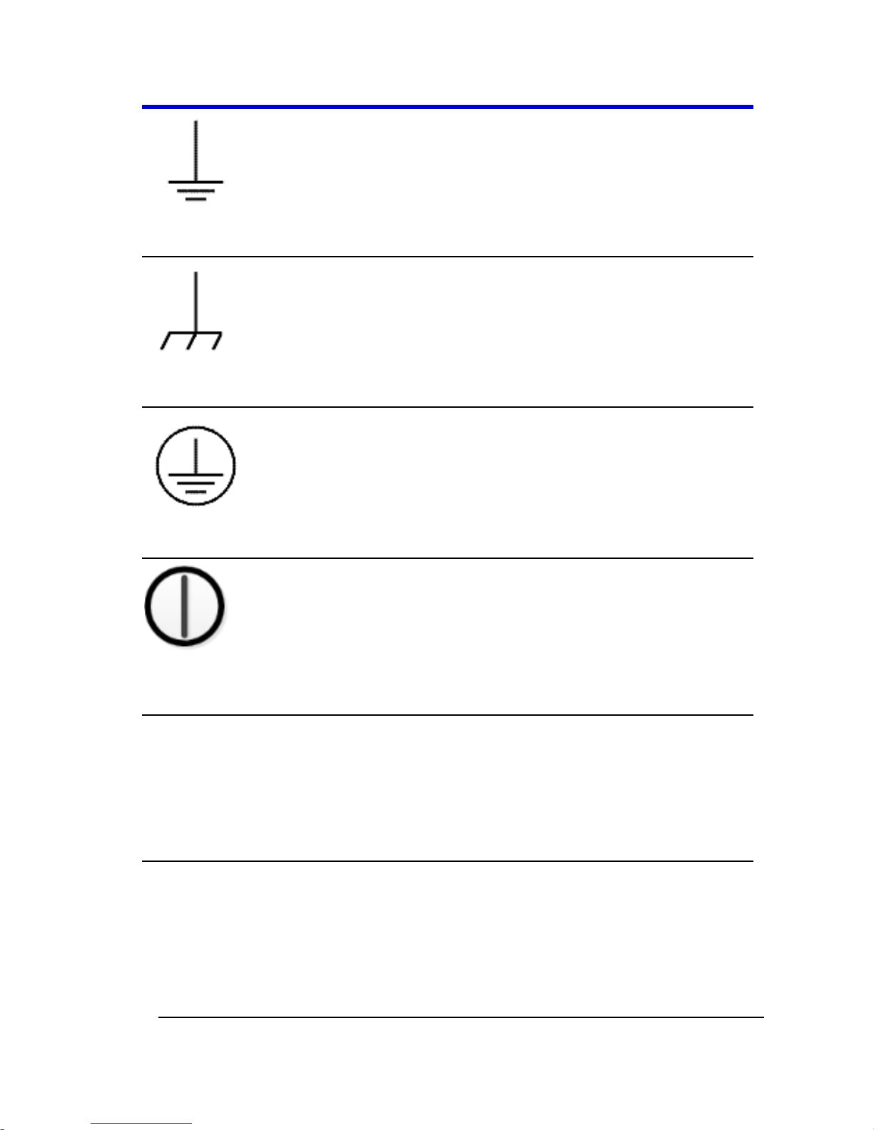
This symbol is used to denote the measurement ground connection.
This symbol is used to denote a frame or chassis connection.
This symbol is used to denote a safety ground connection.
This symbol is used to denote Power. It is located on the front panel and
denotes Power On/Off status of the instrument.
CAUTION
The CAUTION sign indicates a potential hazard. It calls attention to a
procedure, practice or condition which, if not followed, could possibly
cause damage to equipment. If a CAUTION is indicated, do not proceed
until its conditions are fully understood and met.
WARNING
The WARNING sign indicates a potential hazard. It calls attention to a
procedure, practice or condition which, if not followed, could possibly
cause bodily injury or death. If a WARNING is indicated, do not proceed
until its conditions are fully understood and met.
Page 12

WaveStation
10
WSta-OM-E RevA
CAT I
Installation (Overvoltage) Category rating per EN 61010-1 safety standard
and is applicable for the instrument front panel measuring terminals. CAT
I rated terminals must only be connected to source circuits in which
measures are taken to limit transient voltages to an appropriately low
level.
Operating Environment
The instrument is intended for indoor use and should be operated in a
clean, dry environment. Before using this product, ensure that its
operating environment is maintained within these parameters:
Temperature: 0 °C to 40 °C
Humidity: Maximum relative humidity 80% (non-condensing) for
temperatures up to 30 °C decreasing linearly to 50 % relative humidity at
40 °C.
Altitude: Up to 10,000 ft (3,048 m) at or below 30 °C.
Note: Direct sunlight, radiators, and other heat sources should be taken
into account when assessing the ambient temperature.
WARNING
The instrument must not be operated in explosive, dusty, or wet
atmospheres.
CAUTION
Do not exceed the maximum specified front panel terminal voltage
levels. Refer to Specifications for more details.
Page 13
Operator's Manual
WSta-OM-E RevA
11
Cooling
The instrument relies on forced air cooling with an internal fan and
ventilation openings. Care must be taken to avoid restricting the airflow
around the apertures (fan holes) at the side of the instrument.
CAUTION
Do not allow any foreign matter to enter the instrument through the
ventilation holes, etc.
AC Power Source
100-240 VAC (±10%) at 50/60 Hz (±5%) or 100-120 VAC at 400 Hz (±5%)
Automatic AC voltage selection
No manual voltage selection is required because the instrument
automatically adapts to line voltage.
Power Consumption
50 VA (50 W) Max
WARNING - Electrical Shock Hazard
Only use the power cord provided with your instrument.
Calibration
The recommended calibration interval is one year. Calibration should be
performed by qualified personnel only.
Cleaning
Clean only the exterior of the instrument, using a damp, soft cloth. Do
not use chemicals or abrasive elements. Under no circumstances allow
moisture to penetrate the instrument.
Abnormal Conditions
Operate the instrument only as intended by the manufacturer.
Page 14

WaveStation
12
WSta-OM-E RevA
If you suspect the instrument's protection has been impaired, disconnect
the power cord and secure the instrument against any unintended
operation.
The instrument's protection is likely to be impaired if, for example, the
instrument shows visible damage or has been subjected to severe
transport stresses.
Proper use of the instrument depends on careful reading of all
instructions and labels.
WARNING
Any use of the instrument in a manner not specified by the manufacturer
may impair the instrument's safety protection.
Hardware and I/O
Adjusting the Handle
The construction of the handle on your WaveStation can be adjusted to
bridge the front panel and fully-support the weight of the generator
during transport.
Note: Adjust the while gently pulling outward on the two arms where
they attach to the sides of your WaveStation.
Page 15
Operator's Manual
WSta-OM-E RevA
13
You can also move the handle into a tucked position under the generator
for different viewing positions.
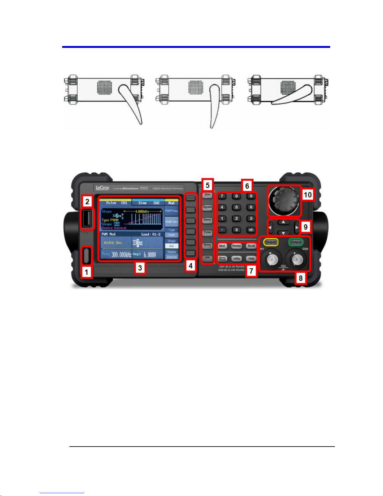
Front Panel
Numbered callouts on this image correspond with the following
descriptions.
1. Power Button
2. USB Connector - USB 2.0 connector which is used for making USB-
GPIB or Memory Stick connections as explained in Controlling
WaveStation with USB-GPIB and/or USBTMC (on page 76) and
Main Save/Recall Operations (on page 57), respectively.
3. LCD Display
4. Display Menu Operation Buttons
5. Waveform Buttons - These buttons control the selection of
Waveform Types and Default Parameters (on page 21).
6. Number Buttons
7. Function Buttons - When pressed, these buttons setup
corresponding Initial Function Settings (on page 22).
Page 16
WaveStation
14
WSta-OM-E RevA
Specifically, the top three buttons are Waveform Signal
Conditioning buttons and apply Mod, Sweep, or Burst functions to
the waveform you've selected. Meanwhile, the lower three,
Save/Recall, Utility, and Help, are for various WaveStation tools
and configurations along with some Help information.
8. BNC Channel Outputs and Corresponding Control Buttons - The
buttons above the BNC connectors control the
activation/deactivation of corresponding channel outputs.
9. Direction Buttons
10. Adjustment Control Knob
Note: When using WaveStation (or any signal generator) it's important
to understand the relationship between the Main Waveform Type
buttons, the Waveform Signal Conditioning function buttons, and the
Save/Recall, Utility, and Help function buttons. See Combined Use of
Waveform, Function, and Configuration Buttons (on page 23).
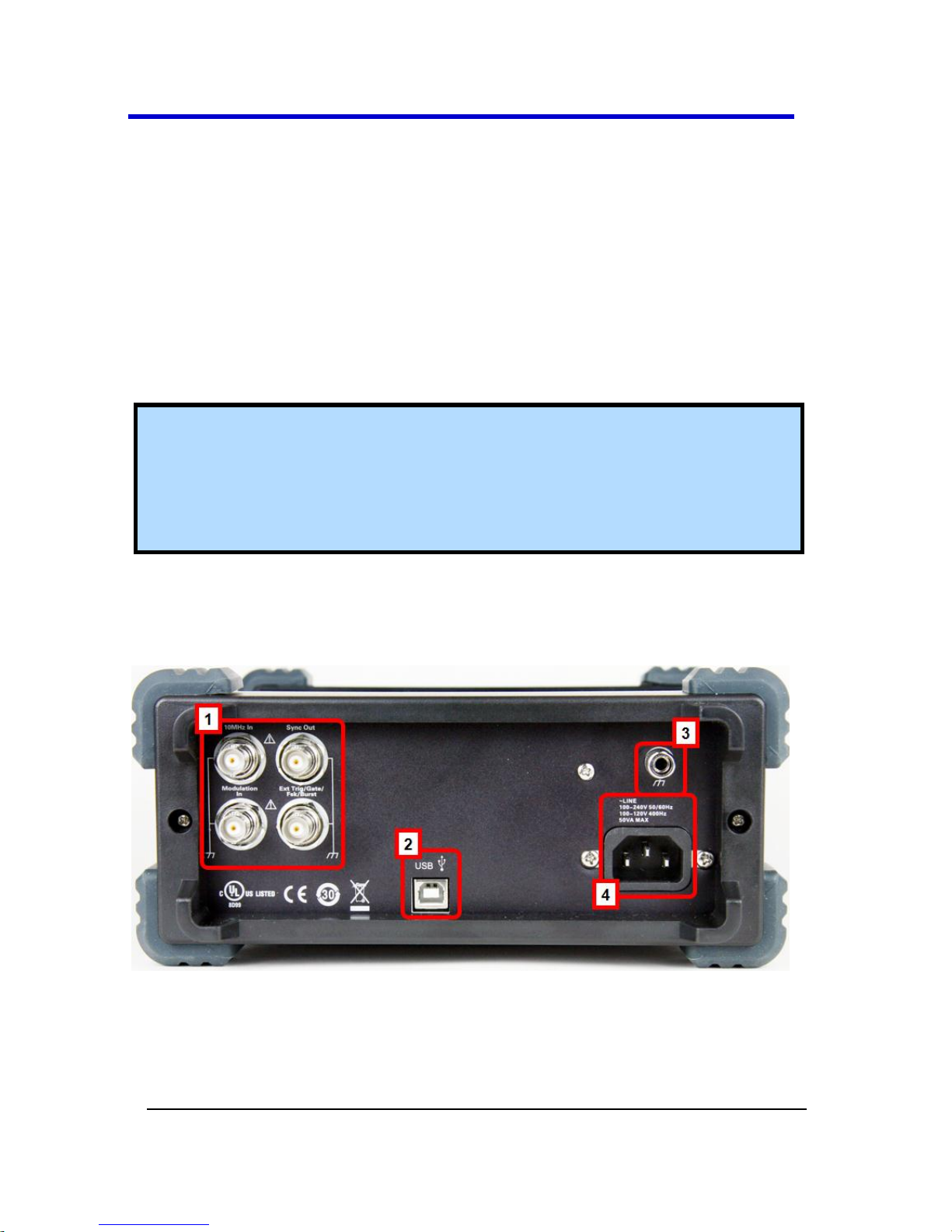
Back Panel
Numbered callouts on this image correspond with the following
descriptions.
1. Input and Output BNC Connectors - Four BNC Connectors provide
10 MHz In, Modulation In, Synch Out, Ext Trig/Gate/Fsk/Burst
Out.
Page 17
Operator's Manual
WSta-OM-E RevA
15
2. USB Connector - USB 2.0 connector which is used for making
USBRAW or USBTMC connections as explained in WaveStation PC
Software Overview (on page 78) and Controlling WaveStation
with USB-GPIB and/or USBTMC (on page 76), respectively.
3. Ground Connector
4. AC Power Connector
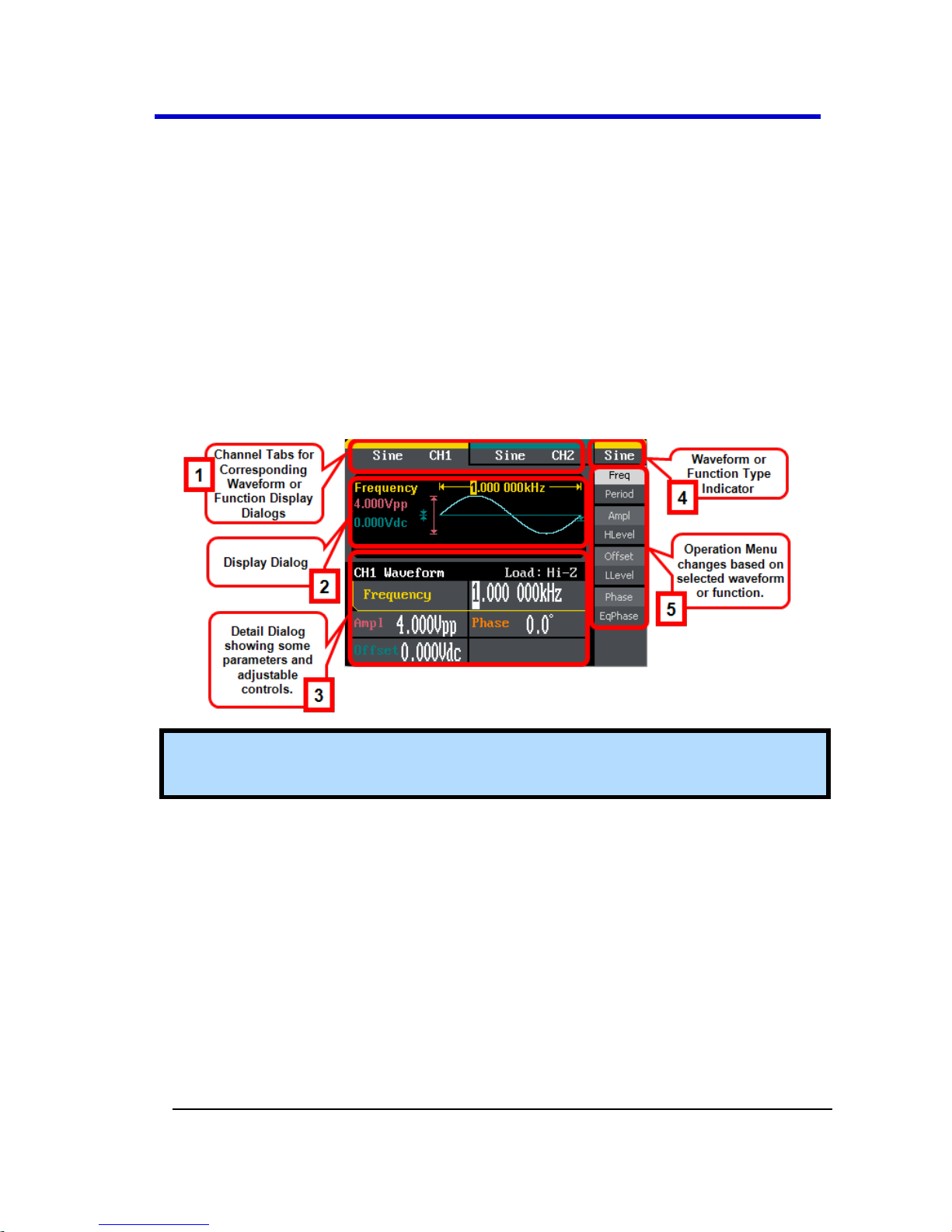
Getting Started with WaveStation
The WaveStation Interface
Numbered callouts on this image of the WaveStation interface
correspond with the following descriptions.
Note: The default signal is a Sine wave as each channel tab and in the
upper-right corner of the display show.
1. Channel Tabs - The channel tabs display the currently chosen
Waveform or Function type and, when selected, show their
corresponding Display and Detail dialog.
2. Display Dialog - Shows a rendered waveform or modulated
waveform display of your generated signal and some additional
waveform details .
3. Detail Dialog - Shows even more data regarding specific
parameters for your selected Waveform or Function.
4. Waveform/Function Type Indicator - When using the Waveform
buttons, shows the waveform type for the corresponding
waveform channel selected.
Page 18

WaveStation
16
WSta-OM-E RevA
Waveform types include Sine, Square, Ramp, Pulse, Noise, and
Arb. When using the Function buttons, shows the selected
function from Modulate, Sweep, Burst, Save/Recall, Utility, and
Help.
5. Operation Menu - This menu changes based on the selected
Waveform or Function chosen. Refer to more detailed
corresponding coverage later in this manual for more information.
Navigating Interfaces, Adjusting Parameters, and
Making Selections
Specific waveform types may be used as carrier waveforms for specific
functions as explained in Initial Function Settings (on page 22).
Note: Default values for most modulated waveform parameters may be
set using certain options available from the Utility menu. Learn more in
Main Utility Operations (on page 62).
Subsequent sections go into more detail when using specific Waveform
and Function buttons and adjusting specific parameters - all of which
vary based on the specific waveform, function, and/or carrier waveform
selections made. This particular topic covers some common navigation,
parameter adjustments, and making selections when using the
WaveStation interfaces.
1. Typically, the first step when using interfaces is to make specific
Waveform or Function button selections on the Front Panel (on
page 13) in order to make specific parameter adjustments or other
selections.
Note: If you've selected a Function button, you now choose a
desired carrier waveform type using the Display Menu
Operation buttons. The waveform is shown on the Waveform
Display.
Page 19
Operator's Manual
WSta-OM-E RevA
17
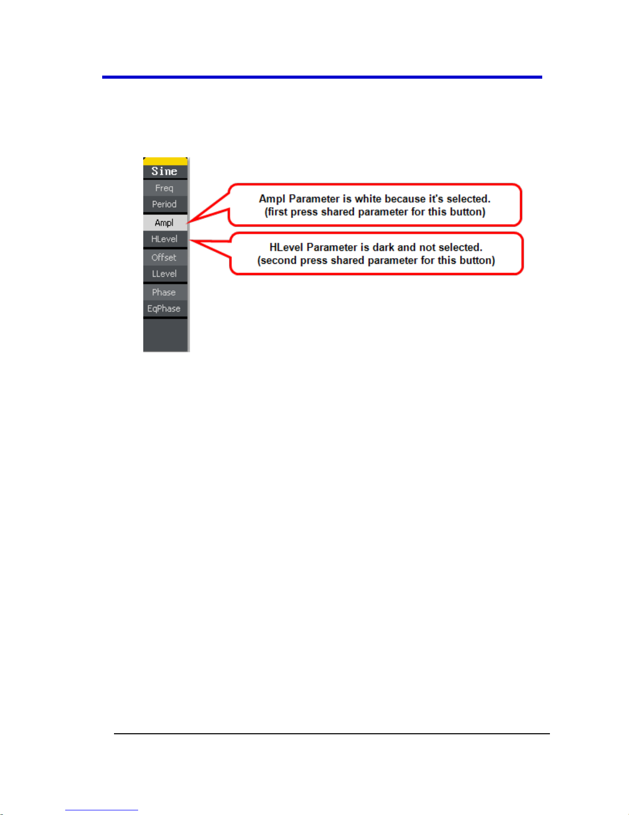
2. At this point, the Display Menu Operation buttons are used to
select applicable parameters and make adjustments as desired.
The operation menu's currently selected parameter is shown in
white.
While navigating, you'll come across the following interfaces and
button type combinations.
First/Second Press Shared Buttons - A good portion of the
operation buttons control two separate parameters.
Operation buttons controlling two parameters have
additional, lighter shaded control labels on them; press the
button once to adjust the top control parameter; twice to
adjust the bottom one. Second operation button press
parameters are shown in reverse color on some interface
dialogs to provide a visual indication as to which parameter
is being adjusted.
Page 20
WaveStation
18
WSta-OM-E RevA
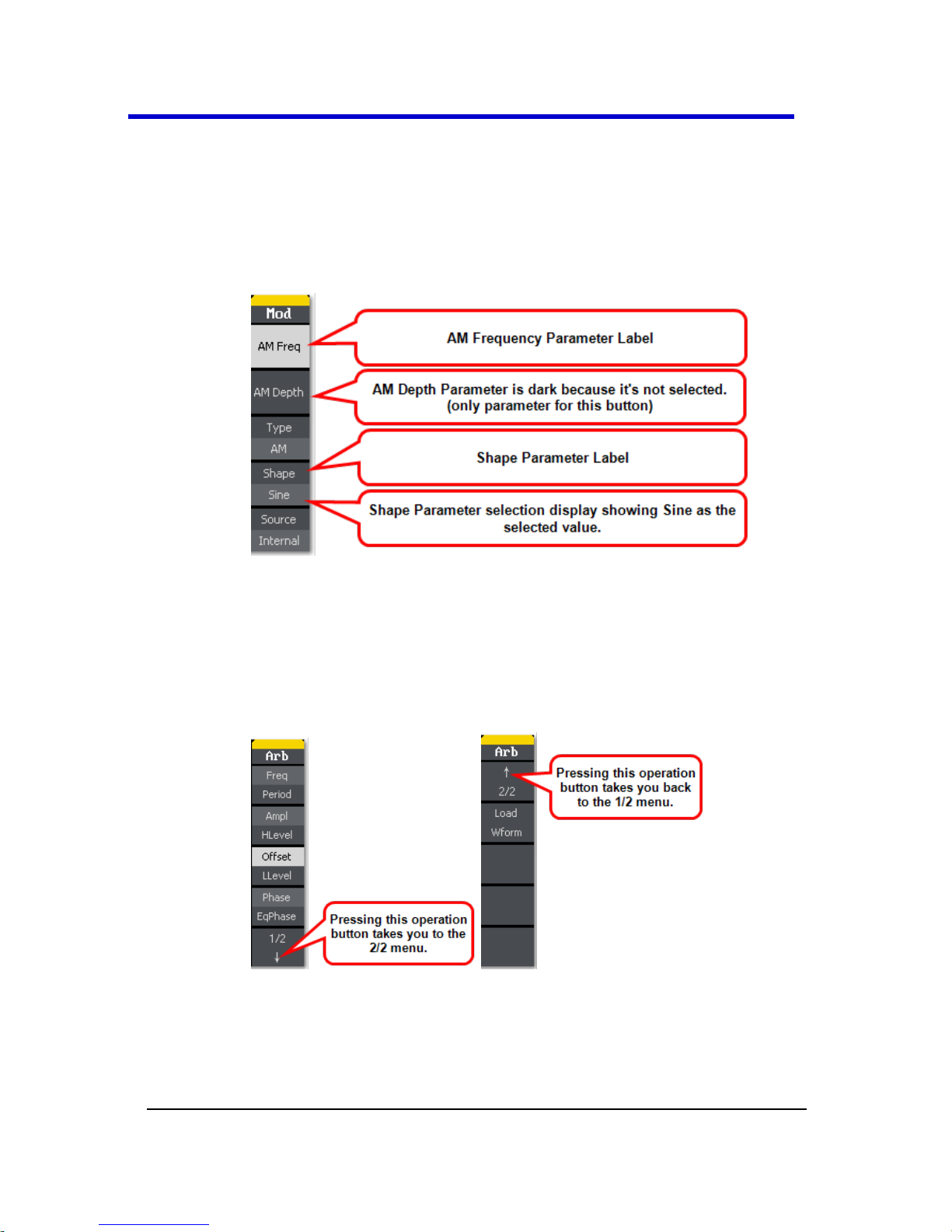
Parameter Label and Selection Display Button - However,
some parameters look like they're first/second press shared
buttons, and really are not. Instead, the parameter title is
shown in the top portion and the lower portion displays the
particular parameter selection as the following Shape
parameter shows.
Additional Menus - Operation menus containing more
parameters than the ones showing on the first menu have a
1/X ↓ final selection. The additional menu(s) therefore
have a 2/X ↑ first selection. Press the adjacent operation
button to navigate additional menu(s) and parameter(s) as
desired.
3. Making the actual parameter adjustments or other selection is
made a few different ways. Most are done by selecting a specific
parameter using a corresponding operation menu button,
changing the value or selection using Digital Input Front Panel
Page 21
Operator's Manual
WSta-OM-E RevA
19
Controls (on page 27), and then pressing the same corresponding
operation menu button again to preserve the
adjustment/selection. The only variation includes where the
interface shows the adjustment/selection choices.
Inside the Operation Menu - Some adjustment/selection
choices are shown right on the Operation menu.
On the Display Dialog - Some adjustment/selection choices
are shown right on the Display dialog.
Page 22
WaveStation
20
WSta-OM-E RevA
On the Detail Dialog - Some adjustment/selection choices
are shown right on the Detail dialog.
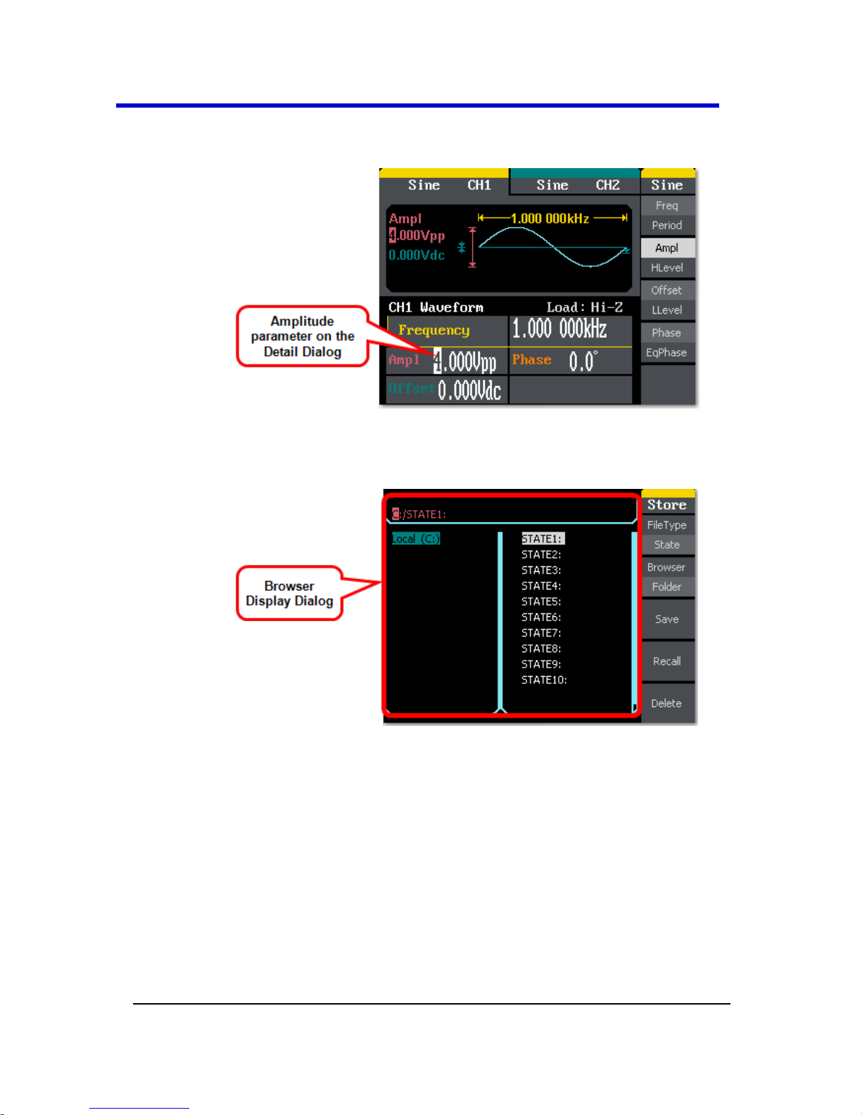
On the Browser Display Dialog - Some interfaces are
provided using file explorer-like screens for saving and
recalling a variety of folders and file types.
Page 23

Operator's Manual
WSta-OM-E RevA
21
Waveform Types and Default Parameters
Provided your WaveStation is powered on, a single waveform type is
always selected and only one waveform type is selected at a time. Each
waveform type (Sine, Square, Ramp, Pulse, Noise, and Arb) contains
default parameters when initially selected.
Note: When using WaveStation (or any signal generator) it's important
to understand the relationship between the Main Waveform Type
buttons, the Waveform Signal Conditioning function buttons, and the
Save/Recall, Utility, and Help function buttons. See Combined Use of
Waveform, Function, and Configuration Buttons (on page 23).
Select waveform types by pressing the corresponding waveform button
on the Front Panel (on page 13).
1. Sine - The default Sine waveform is set to 1 kHz frequency, 4.0 Vpp
amplitude and a 0V dc offset. The WaveStation can produce 1 μHz
up to 50 MHz (WaveStation 2052) Sine waves.
2. Square - The default Square waveform is set to 1 kHz frequency,
4.0 Vpp amplitude, 0V dc offset with a 50% duty cycle. The
WaveStation can produce 1 μHz to 25 MHz with variable duty
cycle Square waves.
3. Ramp - The default Ramp waveform is set to 1 kHz frequency, 4.0
Vpp amplitude, 0V dc offset with a 50% symmetry. The
WaveStation can produce 1 μHz to 300 kHz with variable
symmetry Ramp waves.
4. Pulse - The default Pulse waveform is set to 1 kHz frequency, 4.0
Vpp amplitude, 0V dc offset, 200 μs pulse width. The WaveStation
can produce 500 μHz to 5 MHz with variable pulse width and delay
Pulse waves.
5. Noise - The default Noise waveform is set to 2.0V Variance and 10
mV Mean. The WaveStation can produce signal bandwidth up to
50 MHz for Noise waves.
6. Arb - The default Arb waveform is set to 1 kHz frequency, 4.0 Vpp
amplitude and 0mV dc offset. The WaveStation can produce
repeatable arbitrary waveform signals with a 16K point maximum
and a 5 MHz frequency.
Page 24

WaveStation
22
WSta-OM-E RevA
Initial Function Settings
Each function (Modulate, Sweep, Burst, Save/Recall, Utility, and Help)
contains default settings when initially selected.
Specifically, the top three buttons are Waveform Signal Conditioning
buttons and apply Mod, Sweep, or Burst functions to the waveform
you've selected. Meanwhile, the lower three, Save/Recall, Utility, and
Help, are for various WaveStation tools and configurations along with
some Help information.
Note: When using WaveStation (or any signal generator) it's important
to understand the relationship between the Main Waveform Type
buttons, the Waveform Signal Conditioning function buttons, and the
Save/Recall, Utility, and Help function buttons. See Combined Use of
Waveform, Function, and Configuration Buttons (on page 23).
Select a function by pressing the corresponding function button on the
Front Panel (on page 13).
Waveform Signal Conditioning Buttons
Modulate - Press the Mod button and the modulated waveforms
you've created using the WaveStation are generated. Waveforms
are modulated using AM, FM, ASK, FSK, and PM.
Note: Sine, Square, Ramp, or Arb waveforms may be modulated,
while Pulse, Noise, and DC cannot.
Sweep - Press the Sweep button and the WaveStation produces a
signal with variable frequencies.
Note: Sine, Square, Ramp, or Arb waveforms may be swept,
while Pulse, Noise, and DC cannot.
Page 25

Operator's Manual
WSta-OM-E RevA
23
Burst - Press the Burst button and the waveforms you've created
using the WaveStation are generated for either N-Cycle Burst (a
specified number of waveform cycles) or Gated Burst (controlled
by an external gated signal).
Note: Sine, Square, Ramp, or Arb waveforms may be set to an
N-Cycle Burst, while Noise is the only waveform type available
for a Gated Burst.
Save/Recall, Utility, and Help Buttons
Save/Recall - Press the Save/Recall button to store or arrange
waveform data either on the WaveStation itself or on an external
memory device. This function is also used for retrieving data
previously stored on internal or external memory as well.
Utility - Press the Utility button to set Auxiliary System Functions,
Output Parameters, Interface Settings, and to View System
Setting Information.
Help - Press the Help button and the WaveStation help system is
pertaining to the current function or operation is shown.
Combined Use of Waveform, Function, and
Configuration Buttons
When using WaveStation (or any signal generator) it's important to
understand the relationship between the Main Waveform Type buttons,
the Waveform Signal Conditioning function buttons, and the
Save/Recall, Utility, and Help function Front Panel (on page 13) buttons.
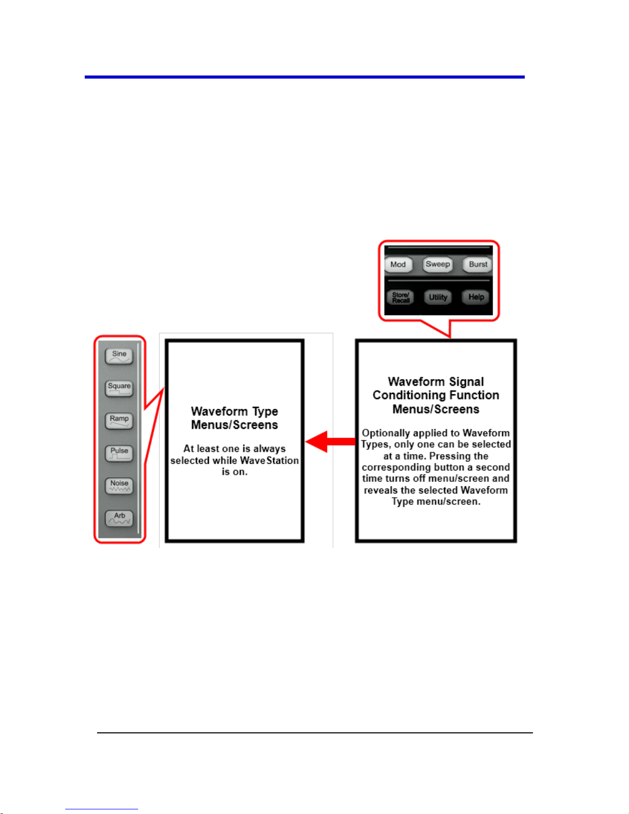
Main Waveform Buttons
As mentioned in Waveform Types and Default Parameters (on page 21),
provided your WaveStation is powered on, a single waveform type is
always selected and only one waveform type is selected at a time.
Waveform Signal Conditioning Function Buttons
As mentioned in Initial Function Settings (on page 22), you apply one of
the three signal conditioning function buttons to your selected waveform
type for specific Mod, Sweep, or Burst functionality.
Page 26
WaveStation
24
WSta-OM-E RevA
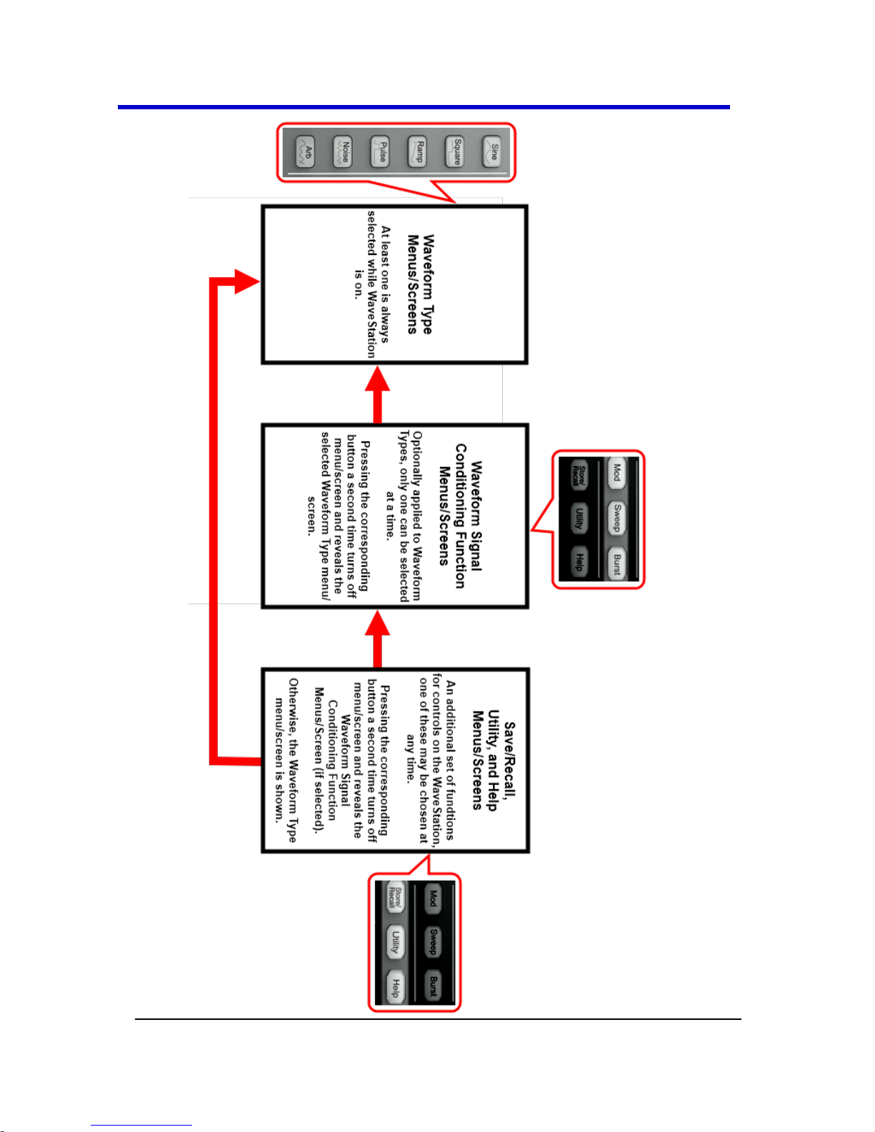
Menus are therefore displayed in a prioritized order of Waveform Type
(one of which is always selected) and a second level of Mod, Sweep, or
Burst (one of the three at a time). However, it is not mandatory to apply
Mod, Sweep, or Burst functionality to your selected waveform.
Therefore, a second press of the Mod, Sweep, or Burst button turns the
LED and function off to reveal the originally selected waveform type
menu.
The menu behavior/relationship looks like the following:
Save/Recall, Utility, and Help Function Buttons
Also mentioned in Initial Function Settings (on page 22), while the
waveform type and an optional signal conditioning function is (or is
not) applied to your signal, you can also use one of the Save/Recall,
Utility, or Help function buttons.
Page 27

Operator's Manual
WSta-OM-E RevA
25
So, at any given time, you can press the Save/Recall, Utility, or Help
function button, and the corresponding menu is shown. Similar to Mod,
Sweep, or Burst these buttons are optional and a second press turns off
their corresponding LED and function to reveal either the the Mod,
Sweep, or Burst menu if applied to the selected waveform, otherwise,
the selected waveform type menu is shown.
The menu behavior/relationship looks like the following:
Page 28
WaveStation
26
WSta-OM-E RevA
Page 29

Operator's Manual
WSta-OM-E RevA
27
Digital Input Front Panel Controls
Three sets of buttons - The Number Buttons, The Direction Buttons, and
the Adjustment Control Knob - all provide unique means to provide
digital input from the Front Panel (on page 13) in the following ways:
1. The Number Buttons are used to set parameter and input values.
2. Up and Down Direction Buttons select through different
parameters while the Left and Right ones are used to
decrease/increase, respectively, preset value increments for a
selected parameter. Also used to navigate the Path, Folder, File
sections of the Browser display dialog in Main Save/Recall
Operations (on page 57).
TIP: Combine Number and Direction buttons to edit a parameter
by using the left direction button to more the cursor backward
and delete or change values entered using the number buttons.
3. The Adjustment Control Knob allows you to decrease/increase
more precise value increments for a selected parameter or select
items from listings when by turning the knob
counterclockwise/clockwise, respectively.
Creating Waveforms
Creating Waveforms Overview
The first step in creating your waveform is to press the corresponding
Waveform button on the Front Panel.
PLEASE NOTE THE FOLLOWING:
When using WaveStation (or any signal generator) it's important
to understand the relationship between the Main Waveform Type
buttons, the Waveform Signal Conditioning function buttons, and
the Save/Recall, Utility, and Help function buttons. See Combined
Use of Waveform, Function, and Configuration Buttons (on page
23).
Default values for many controls can be set using certain options
available on the Utility menu. Learn more in Main Utility
Operations (on page 62).
Page 30
WaveStation
28
WSta-OM-E RevA
This section covers details around creating waveforms and making
specific adjustment/selection parameter choices - all of which vary based
on the specific waveform selection made.
For more information on getting to this point, see Navigating Interfaces,
Adjusting Parameters, and Making Selections (on page 16).
Creating a Sine Wave
When first pressing this waveform button on the Front Panel, the
WaveStation shows the Sine Operation menu and corresponding Display
and Detail dialogs.
Press adjacent Operation buttons and use the Digital Input Front Panel
Controls (on page 27) to make specific adjustment/selection parameter
choices. For more information on getting to this point, see Navigating
Interfaces, Adjusting Parameters, and Making Selections (on page 16).
Sine Operation menu selections and parameters include
Frequency/Period, Amplitude/HLevel, Offset/LLevel, Phase, and Duty
Cycle as explained in the remainder of this topic.
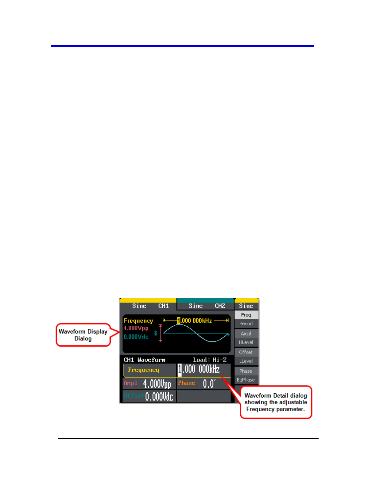
Frequency/Period
With the Sine waveform and the Frequency/Period operation button
pressed once to select Frequency, a Sine waveform is shown on the
Waveform Display and the Frequency is shown on the Waveform Detail
dialog.
Page 31

Operator's Manual
WSta-OM-E RevA
29
PLEASE NOTE THE FOLLOWING:
Press the Frequency/Period operation button a second time to
select and adjust the Period parameter in the same manner.
While editing certain parameters using the Number Buttons,
applicable unit(s) are shown on the Operation menu. Press an
adjacent Operation button to select a desired Unit for your entry.
Provide your desired Frequency or Period using the Digital Input
Front Panel Controls (on page 27).
Amplitude/HLevel
With the Sine waveform and the Amplitude/HLevel operation button
pressed once, a Sine waveform is shown on the Waveform Display and
Amplitude is shown on the Waveform Detail dialog.
PLEASE NOTE THE FOLLOWING:
Page 32

WaveStation
30
WSta-OM-E RevA
Press the Amplitude/HLevel operation button a second time to
select and adjust the HLevel (High Level) parameter in the same
manner. Second operation button press parameters are shown in
reverse color on the waveform detail dialog to provide a visual
indication as to which parameter is being adjusted.
While editing certain parameters using the Number Buttons,
applicable unit(s) are shown on the Operation menu. Press an
adjacent Operation button to select a desired Unit for your entry.
Provide your desired Amplitude or HLevel using the Digital Input
Front Panel Controls (on page 27).
Offset/LLevel
With the Sine waveform and the Offset/LLevel operation button pressed
once to select Offset, a Sine waveform is shown on the Waveform
Display and the Offset is shown on the Waveform Detail dialog.
PLEASE NOTE THE FOLLOWING:
Press the Offset/LLevel operation button a second time to select
and adjust the LLevel (Low Level) parameter in the same manner.
Second operation button press parameters are shown in reverse
color on the waveform detail dialog to provide a visual indication
as to which parameter is being adjusted.
While editing certain parameters using the Number Buttons,
applicable unit(s) are shown on the Operation menu. Press an
adjacent Operation button to select a desired Unit for your entry.
Page 33

Operator's Manual
WSta-OM-E RevA
31
Provide your desired Offset or LLevel using the Digital Input Front
Panel Controls (on page 27).
Phase/EqPhase
With the Sine waveform and the Phase/EqPhase operation button
pressed once to select Frequency, a Sine waveform is shown on the
Waveform Display and the Phase is shown on the Waveform Detail
dialog.
PLEASE NOTE THE FOLLOWING:
Press the Phase/EqPhase operation button a second time to
select and adjust the EqPhase parameter in the same manner.
Second operation button press parameters are shown in reverse
color on the waveform detail dialog to provide a visual indication
as to which parameter is being adjusted.
While editing certain parameters using the Number Buttons,
applicable unit(s) are shown on the Operation menu. Press an
adjacent Operation button to select a desired Unit for your entry.
Provide your desired Phase or EqPhase using the Digital Input
Front Panel Controls (on page 27).
Creating a Square Wave
When first pressing this waveform button on the Front Panel, the
WaveStation shows the Square Operation menu and corresponding
Display and Detail dialogs.
Page 34

WaveStation
32
WSta-OM-E RevA
Press adjacent Operation buttons and use the Digital Input Front Panel
Controls (on page 27) to make specific adjustment/selection parameter
choices. For more information on getting to this point, see Navigating
Interfaces, Adjusting Parameters, and Making Selections (on page 16).
Note: Square Operation menu selections and parameters include
Frequency/Period, Amplitude/HLevel, Offset/LLevel, Phase, and Duty
Cycle. The parameters for Frequency/Period, Amplitude/HLevel,
Offset/LLevel, Phase are carried out the same way as done when
Creating a Sine Wave (on page 28).
Setting the Duty Cycle is done as follows:
Duty Cycle
With the Square waveform and the Duty (Duty Cycle) operation button
pressed, a Square waveform is shown on the Waveform Display and
Duty Cycle is shown on the Waveform Detail dialog.
The Duty Cycle is provided as a % percent of the High Level taking up the
whole period.
Page 35

Operator's Manual
WSta-OM-E RevA
33
% of High Level
Frequency
20 to 80%
< 10 MHz
40 to 60%
From 10 MHz to 20 MHz
50%
> 20 MHz
PLEASE NOTE THE FOLLOWING:
Press an adjacent Operation button to select a desired Unit (unit
interval) for your entry.
Provide your desired Duty Cycle amount using the Digital Input
Front Panel Controls (on page 27).
Creating a Ramp Wave
When first pressing this waveform button on the Front Panel, the
WaveStation shows the Ramp Operation menu and corresponding
Display and Detail dialogs.
Press adjacent Operation buttons and use the Digital Input Front Panel
Controls (on page 27) to make specific adjustment/selection parameter
choices. For more information on getting to this point, see Navigating
Interfaces, Adjusting Parameters, and Making Selections (on page 16).
Note: Ramp Operation menu selections and parameters include
Frequency/Period, Amplitude/HLevel, Offset/LLevel, Phase/EqPhase,
and Symmetry. The parameters for Frequency/Period,
Amplitude/HLevel, Offset/LLevel, Phase/EqPhase are carried out the
same way as done when Creating a Sine Wave (on page 28).
Setting the Symmetry is done as follows:
Page 36

WaveStation
34
WSta-OM-E RevA
Symmetry
With the Ramp waveform and the Symmetry operation button pressed,
a Ramp waveform is shown on the Waveform Display and Symmetry is
shown on the Waveform Detail dialog.
PLEASE NOTE THE FOLLOWING:
Press an adjacent Operation button to select a desired Unit (unit
interval) for your entry.
Provide your desired Symmetry amount using the Digital Input
Front Panel Controls (on page 27).
Creating a Pulse Wave
When first pressing this waveform button on the Front Panel, the
WaveStation shows the Pulse Operation menu and corresponding
Display and Detail dialogs.
Press adjacent Operation buttons and use the Digital Input Front Panel
Controls (on page 27) to make specific adjustment/selection parameter
choices.
Page 37

Operator's Manual
WSta-OM-E RevA
35
For more information on getting to this point, see Navigating Interfaces,
Adjusting Parameters, and Making Selections (on page 16).
Note: Pulse Operation menu selections and parameters include
Frequency/Period, Amplitude/HLevel, Offset/LLevel, PulWidth/Duty,
and Delay. The parameters for Frequency/Period, Amplitude/HLevel,
and Offset/LLevel are carried out the same way as done when Creating
a Sine Wave (on page 28).
Setting the PulWidth/Duty (Pulse Width) and Delay is done as follows:
PulWidth/Duty
With the Pulse waveform and the PulWidth/Duty operation button
pressed once to select PulWidth, a Pulse waveform is shown on the
Waveform Display and the Pulse Width is shown on the Waveform
Detail dialog.
Positive Pulse Width is the time from the first rising edge to the first
falling edge. Similar for Negative Pulse Width.
PLEASE NOTE THE FOLLOWING:
Press an adjacent Operation button to select a desired Unit (unit
interval) for your entry.
Provide your desired PulWidth amount using the Digital Input
Front Panel Controls (on page 27).
Page 38

WaveStation
36
WSta-OM-E RevA
Delay
With the Pulse waveform and the Delay operation button pressed once,
a Pulse waveform is shown on the Waveform Display and the Delay is
shown on the Waveform Detail dialog.
PLEASE NOTE THE FOLLOWING:
Press an adjacent Operation button to select a desired Unit (unit
interval) for your entry.
Provide your desired Delay amount using the Digital Input Front
Panel Controls (on page 27).
Creating a Noise Wave
When first pressing this waveform button on the Front Panel, the
WaveStation shows the Noise Operation menu and corresponding
Display and Detail dialogs.
Press adjacent Operation buttons and use the Digital Input Front Panel
Controls (on page 27) to make specific adjustment/selection parameter
choices. For more information on getting to this point, see Navigating
Interfaces, Adjusting Parameters, and Making Selections (on page 16).
Page 39

Operator's Manual
WSta-OM-E RevA
37
Set Variance/Mean values on Noise Waveforms as follows:
Variance/Mean
With the Noise waveform and the Variance/Mean operation button
pressed once to select Variance, a Noise waveform is shown on the
Waveform Display and Variance is shown on the Waveform Detail
dialog.
PLEASE NOTE THE FOLLOWING:
Press the Variance/Mean operation button a second time to
select and adjust the Mean parameter in the same manner.
While editing certain parameters using the Number Buttons,
applicable unit(s) are shown on the Operation menu. Press an
adjacent Operation button to select a desired Unit for your entry.
Provide your desired Variance or Mean values using the Digital
Input Front Panel Controls (on page 27).
Creating an Arbitrary Waveform
When first pressing this waveform button on the Front Panel, the
WaveStation shows the Arb Operation menu and corresponding Display
and Detail dialogs. There is a System Default Arb Waveform and a User-
Defined Arb Waveform.
Page 40

WaveStation
38
WSta-OM-E RevA
Press adjacent Operation buttons and use the Digital Input Front Panel
Controls (on page 27) to make specific adjustment/selection parameter
choices. For more information on getting to this point, see Navigating
Interfaces, Adjusting Parameters, and Making Selections (on page 16).
PLEASE NOTE THE FOLLOWING:
Arb Operation menu selections and parameters include
Frequency/Period, Amplitude/HLevel, Offset/LLevel,
Phase/EqPhase, and Load Wform. The parameters
forFrequency/Period, Amplitude/HLevel, Offset/LLevel, and
Phase/EqPhase are carried out the same way as done when
Creating a Sine Wave (on page 28).
Operation menus containing more parameters than the ones
showing on the first menu have a 1/X ↓ final selection. The
additional menu(s) therefore have a 2/X ↑ first selection. Press
the adjacent button to navigate additional menu(s) and
parameter(s) as desired.
Loading a Stored Waveform is done as follows:
Load Wform
Press the 1/2 ↓ button to access the additional Arb Operation
menu.
Now, press the Load Wform button.
An Arb menu showing Built-In and Stored Waveform options is
shown.
Note: There are 40+ Built-In Arbitrary Waveforms available in
the WaveStation.
Page 41

Operator's Manual
WSta-OM-E RevA
39
BUILT-IN ARBITRARY WAVEFORMS
After selecting Arb → Load Wform → Built-In, a menu is shown
categorizing the Built-In Arbitrary Waveforms as follows:
Note: After selecting one of the following categories using the adjacent
Operation button, the built-in waveforms are shown on the Waveform
Display dialog and may be selected using the Digital Input Front Panel
Controls (on page 27) - specifically, the Direction Buttons or the
Control Knob. Make your selection by pressing the Select option
button.
Common - Common Built-In Arbitrary Waveforms include StairUp,
StairDn, StairUD (Stair Up and Down), PPulse (Positive Pulse),
NPulse (Negative Pulse), Trapezia (Trapezoid), UpRamp, and
DnRamp.
Math - Math Built-In Arbitrary Waveforms include ExpFall
(Exponential Fall), ExpRise, LogFall (Logarithmic Fall), LogRise, Sqrt
(Square Root), Root3, X^2, X^3, Sinc, Gaussian, Dlorentz (D-
Lorentz), Haversin (Haversine), Lorentz, Gauspuls (Gaussian-
modulated sinusoidal pulse), Gmonpuls (Gaussian monopulse),
and Tripuls (triangle pulse).
Project - Project Built-In Arbitrary Waveforms include Cardiac
(electrocardiogram or ECG), Quake (loma prieta earthquake),
Chirp (swept-frequency cosine), TwoTone (two tone signal), and
SNR (sine wave with white noise).
Winfun/Triangle - Winfun/Triangle Built-In Arbitrary Waveforms
include Hamming, Hanning, Kaiser, Blackman, Gaussian, Triangle,
Hairs, Bartlett, Tan, Cot, Sec, Csc, Asin, Acos, Atan, and Acot.
Choice - Choice Built-In Arbitrary Waveforms include StairUp,
StairDn, StairUD (Stair Up and Down), PPulse (Positive Pulse),
NPulse (Negative Pulse), Trapezia (Trapezoid), UpRamp, and
DnRamp.
Page 42

WaveStation
40
WSta-OM-E RevA
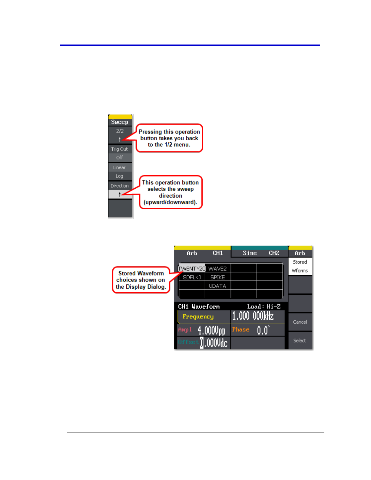
STORED WAVEFORMS
After selecting Arb → Load Wform → Stored Wforms, the Stored
Waveforms are shown on the Waveform Display dialog as follows:
Note: Select the stored waveforms showing on the Waveform Display
dialog using the Digital Input Front Panel Controls (on page 27) -
specifically, the Direction Buttons or the Control Knob. Make your
selection by pressing the Select option button.
Page 43

Operator's Manual
WSta-OM-E RevA
41
Generating Modulated Waveforms
Generating Modulated Waveforms Overview
Specific waveform types may be modulated (as carrier waveforms) using
the WaveStation. Sine, Square, Ramp, or Arb waveforms may be
modulated, while Pulse, Noise, and DC cannot.
The first step in creating your modulated waveform is to press the Mod
Function button on the Front Panel. Then, select a modulated waveform
type from the AM, FM, ASK, FSK, PM, and PWM choices on the Mod
operation menu.
PLEASE NOTE THE FOLLOWING:
When using WaveStation (or any signal generator) it's important
to understand the relationship between the Main Waveform Type
buttons, the Waveform Signal Conditioning function buttons, and
the Save/Recall, Utility, and Help function buttons. See Combined
Use of Waveform, Function, and Configuration Buttons (on page
23).
Default values for many controls can be set using certain options
available on the Utility menu. Learn more in Main Utility
Operations (on page 62).
This section covers details around creating modulated waveforms and
making specific adjustment/selection parameter choices - all of which
vary based on the specific function and carrier waveform selection
made.
For more information on getting to this point, see Navigating Interfaces,
Adjusting Parameters, and Making Selections (on page 16).
Generating an AM (Amplitude Modulation)
Modulated Waveform
After selecting the Mod → AM modulated waveform operator button as
explained in the Generating Modulated Waveforms Overview (above),
the WaveStation shows the AM Operation menu and corresponding
Display and Detail dialogs.
Page 44

WaveStation
42
WSta-OM-E RevA
Press adjacent Operation buttons and use the Digital Input Front Panel
Controls (on page 27) to make specific adjustment/selection parameter
choices. For more information on getting to this point, see Navigating
Interfaces, Adjusting Parameters, and Making Selections (on page 16).
Mod → AM Operation menu selections and parameters include AM Freq,
AM Depth, Type, Shape, and Source as follows:
AM Freq - This parameter sets the modulating waveform
frequency. The internal source frequency range is 2 MHz to 20
kHz.
AM Depth - This parameter sets the amplitude range.
Note: Amplitude range is also referred to as amplitude depth or
percentage modulation. It's a percentage value that varies from
1 to 120% . When set to 0%, the output amplitude is
approximately half of the user set amplitude value.When set to
0%, the output amplitude is approximately half of the user set
amplitude value. When set to 100%, the output amplitude
matches the amplitude set. When using an external source, the
AM depth is controlled by the voltage level of the connector
attached to Modulation In on the Back Panel (on page 14). ±6V
corresponds to 100% of your current depth setting.
Type - Amplitude modulation.
Shape - Choose the waveform shape type (used as a carrier
waveform) for modulation. Sine, Square, Ramp, or Arb waveforms
may be modulated, while Pulse, Noise, and DC cannot.
Source - Select Internal or External. If External is selected, use the
Modulation In connector on the Back Panel (on page 14).
Generating a FM (Frequency Modulation)
Modulated Waveform
After selecting the Mod → FM modulated waveform operator button as
explained in the Generating Modulated Waveforms Overview (on page
41), the WaveStation shows the FM Operation menu and corresponding
Display and Detail dialogs.
Page 45

Operator's Manual
WSta-OM-E RevA
43
Press adjacent Operation buttons and use the Digital Input Front Panel
Controls (on page 27) to make specific adjustment/selection parameter
choices. For more information on getting to this point, see Navigating
Interfaces, Adjusting Parameters, and Making Selections (on page 16).
Mod → FM Operation menu selections and parameters include FM Freq,
FM Dev, Type, Shape, and Source as follows:
FM Freq - This parameter sets the modulating waveform
frequency. The internal source frequency range is 2 MHz to 20
kHz.
FM Dev - This parameter sets the maximum frequency deviation.
Note: The frequency deviation value should be ≤ the carrier
waveform frequency. The sum of the deviation and the carrier
waveform frequency should be ≤ the maximum frequency of the
selected waveform. When using an external source, the
deviation is controlled by the voltage level of the connector
attached to Modulation In on the Back Panel (on page 14). +6V
corresponds to the selected deviation and -6V to the negative
selected deviation. So, a +/- 6 V input results in an output FM
deviation equal to the preset FM deviation
Type - Frequency modulation.
Shape - Choose the waveform shape type (used as a carrier
waveform) for modulation. Sine, Square, Triangle, UpRamp,
DnRamp, Noise, or Arb waveforms may be modulated, while
Pulse, and DC cannot.
Source - Select Internal or External. If External is selected, use the
Modulation In connector on the Back Panel (on page 14).
Generating an ASK (Amplitude Shift Keying
Modulation) Modulated Waveform
After selecting the Mod → ASK modulated waveform operator button as
explained in the Generating Modulated Waveforms Overview (on page
41), the WaveStation shows the ASK Operation menu and corresponding
Display and Detail dialogs.
Page 46

WaveStation
44
WSta-OM-E RevA
Press adjacent Operation buttons and use the Digital Input Front Panel
Controls (on page 27) to make specific adjustment/selection parameter
choices. For more information on getting to this point, see Navigating
Interfaces, Adjusting Parameters, and Making Selections (on page 16).
ASK modulation represents digital data as variations in the amplitude of a
carrier wave. The amplitude of an analog carrier signal varies in
accordance with the bit stream (modulating signal), keeping frequency
and phase constant.
Mod → ASK Operation menu selections and parameters include Key
Freq, Type, and Source as follows:
Key Freq - This parameter sets the frequency at which the output
amplitude shifts between the carrier amplitude and 0. The internal
source frequency range is 2 MHz to 50 kHz.
Type - Amplitude Shift Keying Modulation.
Source - Select Internal or External. If External is selected, use the
Trig/Gate/Fsk/Burst connector on the Back Panel (on page 14).
Page 47

Operator's Manual
WSta-OM-E RevA
45
Generating an FSK (Frequency Shift Keying
Modulation) Modulated Waveform
After selecting the Mod → FSK modulated waveform operator button as
explained in the Generating Modulated Waveforms Overview (on page
41), the WaveStation shows the FSK Operation menu and corresponding
Display and Detail dialogs.
Press adjacent Operation buttons and use the Digital Input Front Panel
Controls (on page 27) to make specific adjustment/selection parameter
choices. For more information on getting to this point, see Navigating
Interfaces, Adjusting Parameters, and Making Selections (on page 16).
FSK modulation is an output frequency that switches from the carrier
waveform and hop preset frequencies at a specific point. The specific
frequency point where the output switches is the Key Frequency. The
Key Frequency is determined by the internal frequency generator or the
signal voltage level from the Trig/Gate/Fsk/Burstconnector on the Back
Panel (on page 14).
Mod/ASK Operation menu selections and parameters include Key Freq,
Type, and Source as follows:
Key Freq - This parameter sets the frequency at which the output
frequency shifts between the carrier amplitude and the hop
frequecy. The internal source frequency range is 2 MHz to 50 kHz.
Type - Frequency Shift Keying Modulation.
Page 48

WaveStation
46
WSta-OM-E RevA
Hop Freq - Specify the desired hop frequency level (for variation
from the set carrier waveform frequency).
Source - Select Internal or External. If External is selected, use the
Trig/Gate/Fsk/Burst connector on the Back Panel (on page 14).
Generating an PM (Phase Modulation) Modulated
Waveform
After selecting the Mod → PM modulated waveform operator button as
explained in the Generating Modulated Waveforms Overview (on page
41), the WaveStation shows the PM Operation menu and corresponding
Display and Detail dialogs.
Press adjacent Operation buttons and use the Digital Input Front Panel
Controls (on page 27) to make specific adjustment/selection parameter
choices. For more information on getting to this point, see Navigating
Interfaces, Adjusting Parameters, and Making Selections (on page 16).
Modulated waveforms are one part carrier waveform; the other
modulated. For PM, the phase of the carrier waveform varies with the
instantaneous voltage level of the modulated waveform.
Page 49

Operator's Manual
WSta-OM-E RevA
47
Mod/PM Operation menu selections and parameters include PM Freq,
Phase Dev, Type, Shape, and Source as follows:
PM Freq - This parameter sets the frequency at which the output
amplitude shifts between the carrier amplitude and 0. The internal
source frequency range is 2 MHz to 50 kHz.
Phase Dev - This parameter sets the maximum phase deviation.
Values range from 0° to 360°.
Type - Phase Modulation.
Shape - Choose the waveform shape type (used as a carrier
waveform) for modulation. Sine, Square, Triangle, UpRamp,
DnRamp, Noise, or Arb waveforms may be modulated, while
Pulse, and DC cannot.
Source - Select Internal or External. If External is selected, use the
Trig/Gate/Fsk/Burst connector on the Back Panel (on page 14).
Generating Sweep Waveforms
Specific waveform types may be swept (as carrier waveforms) using the
WaveStation. Sine, Square, Ramp, or Arb waveforms may be swept,
while Pulse, Noise, and DC cannot. Frequency sweep mode uses the
WaveStation to sweep from the start frequency to the stop frequency at
a specified sweep rate.
The first step in creating a sweep waveform is to press the Sweep button
on the Front Panel (on page 13).
PLEASE NOTE THE FOLLOWING:
When using WaveStation (or any signal generator) it's important
to understand the relationship between the Main Waveform Type
buttons, the Waveform Signal Conditioning function buttons, and
the Save/Recall, Utility, and Help function buttons. See Combined
Use of Waveform, Function, and Configuration Buttons (on page
23).
Default values for many controls can be set using certain options
available on the Utility menu. Learn more in Main Utility
Operations (on page 62).
Page 50

WaveStation
48
WSta-OM-E RevA
This section covers sweep waveform creation and making specific
adjustment/selection parameter choices - all of which vary based on the
specific function and carrier waveform selection made.
While details around creating waveforms and adjusting specific
parameters (which vary based on the specific sweep waveform) are
covered here, the following section covers some menu control
considerations.
For more information on getting to this point, see Navigating Interfaces,
Adjusting Parameters, and Making Selections (on page 16).
Common Sweep Waveform Menu Controls and
Considerations
After pressing the Sweep button on the Front Panel (on page 13),
select the desired modulated waveform type using the Display
Menu Operation buttons. The waveform is shown on the
Waveform Display.
At this point, the Display Menu Operation buttons are used to
select applicable parameters and make adjustments as desired.
A good portion of the waveform operation buttons control two
separate parameters. Operation buttons controlling two
parameters have additional, lighter shaded function labels on
them; press the button once to adjust the top control parameter;
twice to adjust the bottom one. Make adjustments using the
Digital Input Front Panel Controls (on page 27).
Second operation button press parameters are shown in reverse
color on the waveform detail dialog to provide a visual indication
as to which parameter is being adjusted in the detail dialog.
Page 51

Operator's Manual
WSta-OM-E RevA
49
PLEASE NOTE THE FOLLOWING:
Some parameters look like they're first/second press shared
and really are not. Instead the parameter title is shown in
the top portion and the lower portion displays the
particular parameter selection.
Operation menus containing more parameters than the
ones showing on the first menu have a 1/X ↓ final
selection. The additional menu(s) therefore have a 2/X ↑
first selection. Press the adjacent button to navigate
additional menu(s) and parameter(s) as desired.
Frequency sweep mode uses the WaveStation to sweep from the start
frequency to the stop frequency at a specified sweep rate.
Page 52

WaveStation
50
WSta-OM-E RevA
Press adjacent Operation buttons and use the Digital Input Front Panel
Controls (on page 27) to make specific adjustment/selection parameter
choices.
Sweep Operation menu selections and parameters include SwpTime,
StopFreq, FreqSpan, StartFreq, MidFreq, Source, TrigOut, Linear/Log,
and Direction as follows:
SwpTime - This parameter sets the overall sweep time span in
which the frequency changes from specified start frequency to
stop frequency values.
StopFreq - Provide a specific frequency value where the sweep
must end.
FreqSpan - Provide an overall span or range in which the sweep
must remain.
StartFreq - Provide a specific frequency value where the sweep is
to begin.
MidFreq - Specify a frequency where the center of the sweep
must remain.
Source - Select Internal, External, or Manual. If External is
selected, use the Trig/Gate/Fsk/Burst connector on the Back
Panel (on page 14). You can also select Manual and specify exact
start and stop times.
TrigOut - Select Off or Open. Open sets trigger on the rising edge
of the waveform.
Page 53

Operator's Manual
WSta-OM-E RevA
51
Linear/Log - Press this operation button to highlight and select
either Linear or Log spacing for your sweep waveform.
Direction - Press this operation button to toggle between an
upward (↑) or downward (↓) sweep direction for your
waveform.
Generating Burst Waveforms
Specific waveform types may be burst using the WaveStation. Sine,
Square, Ramp, or Arb waveforms may be set to an N-Cycle Burst, while
Noise is the only waveform type available for a Gated Burst.
The first step in creating a burst waveform is to press the Burst button on
the Front Panel (on page 13).
PLEASE NOTE THE FOLLOWING:
When using WaveStation (or any signal generator) it's important
to understand the relationship between the Main Waveform Type
buttons, the Waveform Signal Conditioning function buttons, and
the Save/Recall, Utility, and Help function buttons. See Combined
Use of Waveform, Function, and Configuration Buttons (on page
23).
Default values for many controls can be set using certain options
available on the Utility menu. Learn more in Main Utility
Operations (on page 62).
This section covers burst waveform creation and making specific
adjustment/selection parameter choices - all of which vary based on the
specific function and carrier waveform selection made.
While details around creating waveforms and adjusting specific
parameters (which vary based on the specific burst waveform) are
covered here, the following section covers some menu control
considerations.
For more information on getting to this point, see Navigating Interfaces,
Adjusting Parameters, and Making Selections (on page 16).
Page 54

WaveStation
52
WSta-OM-E RevA
Common Burst Waveform Menu Controls and
Considerations
After pressing the Burst button on the Front Panel (on page 13),
select the desired modulated waveform type using the Display
Menu Operation buttons. The waveform is shown on the
Waveform Display.
At this point, the Display Menu Operation buttons are used to
select applicable parameters and make adjustments as desired.
A good portion of the waveform operation buttons control two
separate parameters. Operation buttons controlling two
parameters have additional, lighter shaded function labels on
them; press the button once to adjust the top control parameter;
twice to adjust the bottom one. Make adjustments using the
Digital Input Front Panel Controls (on page 27).
Second operation button press parameters are shown in reverse
color on the waveform detail dialog to provide a visual indication
as to which parameter is being adjusted in the detail dialog.
Page 55

Operator's Manual
WSta-OM-E RevA
53
PLEASE NOTE THE FOLLOWING:
Some parameters look like they're first/second press shared
and really are not. Instead the parameter title is shown in
the top portion and the lower portion displays the
particular parameter selection.
Operation menus containing more parameters than the
ones showing on the first menu have a 1/X ↓ final
selection. The additional menu(s) therefore have a 2/X ↑
first selection. Press the adjacent button to navigate
additional menu(s) and parameter(s) as desired.
Press adjacent Operation buttons and use the Digital Input Front Panel
Controls (on page 27) to make specific adjustment/selection parameter
choices.
Page 56

WaveStation
54
WSta-OM-E RevA
Burst Operation menu selections and parameters include Period,
StartPhase, NCycle/Gated, Source, TrigOut, Cycles/Infinite, and Delay as
follows:
Period - This control is only available when NCycle is selected from
the third operation button. Press the Period operation button and
provide a specific value for the Pulse Period control using the
detail dialog.
StartPhase - Press this operation button and provide a specific
phase value (in °) using the detail dialog to define the starting
point of the waveform. The phase varies from 0° to 360°, and the
default setting is 0°. For an Arbitrary Waveform, 0° is the first
waveform point.
NCycle/Gated - Press this operation button to select either NCycle
or Gated for your burst waveform(s). Many controls on the Burst
operation menu change based on the selection made on this
control. When NCycle is selected, you can press the Period
operation button and provide a specific value for the Pulse Period
control using the detail dialog.
Note: The period time increases if necessary to allow the
specified number of cycles in a burst. The following formula is
applied to the logic of this control:
Burst Period > Carrier Period × Burst Number
N-Cycle has a specific number of waveform cycles and every burst
is activated by a trigger event, whereas a Gated burst is activated
by an external source.
Source - This control is only available when NCycle is selected from
the third operation button. Select Internal, External, or Manual. If
External is selected, use the Trig/Gate/Fsk/Burst connector on the
Back Panel (on page 14). You can also select Manual and specify
exact start and stop times.
TrigOut - This control is only available when NCycle is selected
from the third operation button. Select Off, rising edge (↑), or
falling edge (↓) as desired.
Page 57

Operator's Manual
WSta-OM-E RevA
55
Cycles/Infinite - This control is only available when NCycle is
selected from the third operation button. Press this operation
button to highlight and select either Cycles or Infinite amounts for
your burst waveform(s). With Cycle selected, provide a desired
amount of repetitions (from 1 to 50,000) using the detail dialog.
Infinite generates a continuous waveform that only stops on a
trigger event.
PLEASE NOTE THE FOLLOWING:
The period time increases if necessary to allow the specified
number of cycles in a burst as previously mentioned in the
NCycle/Gated bullet.
An external or manual trigger is required in order to
activate an infinite burst.
Delay - This control is only available when NCycle is selected from
the third operation button. With Delay selected, you can specify a
span of time between the trigger input and the start of the N-Cycle
burst using the detail dialog. The minimum delay amount is 240
ns.
Polarity - This control is only available when Gated is selected
from the third operation button. Press this operation button to
select either Positive or Negative polarity for your gated signal.
Page 58

WaveStation
56
WSta-OM-E RevA
Save/Recall
Save/Recall Overview
The first step when using the Save/Recall is to press the corresponding
Save/Recall function button on the Front Panel (on page 13).
The following interface is shown with the Store Operation menu on the
right side of the screen.
PLEASE NOTE THE FOLLOWING:
When using WaveStation (or any signal generator) it's important
to understand the relationship between the Main Waveform Type
buttons, the Waveform Signal Conditioning function buttons, and
the Save/Recall, Utility, and Help function buttons. See Combined
Use of Waveform, Function, and Configuration Buttons (on page
23).
Default values for many controls can be set using certain options
available on the Utility menu. Learn more in Main Utility
Operations (on page 62).
Page 59

Operator's Manual
WSta-OM-E RevA
57
Main Save/Recall Operations
After pressing the Save/Recall button on the Front Panel (on page 13),
select the desired function using the corresponding Display Menu
Operation buttons.
Note: Default values for most save/recall parameters may be set using
certain options available from the Utility menu. Learn more in Main
Utility Operations (on page 62).
The main screen area or Browser shows a Path, Directory, File display
dialog which is used with Digital Input Front Panel Controls (on page 27)
to specify locations for saved and recalled items.
While details around saving and recalling different folders and file types
are covered here, the following section covers some menu control
considerations.
For more information on getting to this point, see Navigating Interfaces,
Adjusting Parameters, and Making Selections (on page 16).
Common Save/Recall Menu Controls and Considerations
After pressing the Save/Recall button on the Front Panel (on page
13), the Display Menu Operation buttons are used to select
applicable parameters and make adjustments as desired.
Page 60

WaveStation
58
WSta-OM-E RevA
A good portion of the operation buttons control two separate
parameters. Operation buttons controlling two parameters have
additional, lighter shaded function labels on them; press the
button once to adjust the top control parameter; twice to adjust
the bottom one. Make adjustments using the Digital Input Front
Panel Controls (on page 27).
Second operation button press parameters are shown in reverse
color on the waveform detail dialog to provide a visual indication
as to which parameter is being adjusted in the detail dialog.
PLEASE NOTE THE FOLLOWING:
Some parameters look like they're first/second press shared
and really are not. Instead the parameter title is shown in
the top portion and the lower portion displays the
particular parameter selection.
Some operation menus contain more parameters than the
ones showing on the first menu. When this is the case, a
1/X ↓ final selection is provided. The additional menu(s)
therefore have a 2/X ↑ first selection. Press the adjacent
button to navigate additional menu(s) and parameter(s) as
desired.
Operation Menu Selections and Parameters
Operation menu selections and parameters for Save/Recall include the
following:
Page 61

Operator's Manual
WSta-OM-E RevA
59
FileType - This control contains State, Data, and All File options
based on which kinds of files are being used. State (or Setup)
handles various WaveStation setup files, Data handles arbitrary
waveform files, and All File is used when storing or recalling any
other file type.
PLEASE NOTE THE FOLLOWING:
When saving State (Setup) or Data (Arbitrary Waveforms)
onto your WaveStation, 10 specific Memory Banks are
provided for each type on the File section of the Browser.
When a Save is completed, the name you provide is shown
to the right of the specific bank.
Browser - This control contains Path, Folder, and File options.
Successively pressing the Browser option button places the cursor
in corresponding sections of the Browser display dialog where you
can then use Digital Input Front Panel Controls (on page 27) to
make appropriate input selections.
Note: The Direction Buttons on the Digital Input Front Panel
Controls (on page 27) are used to make Folder and File
selections which are then shown on the Path display area of the
Browser.
Save - Once you've made all selections on the aforementioned
control options for Setup or Data and navigated to the desired
storage location, press this control button to and Save your file.
Page 62

WaveStation
60
WSta-OM-E RevA
PLEASE NOTE THE FOLLOWING:
If you're saving State (Setup) or Data (Arbitrary
Waveforms) onto your WaveStation, onto one of their 10
specific Memory Banks, and select a Bank/File location
already containing previously stored information, your new
information always overwrites the old.
When saving information, Digital Input Front Panel
Controls (on page 27) are used to provide a file name in the
following manner:
o Press The Number Buttons to quickly input a number or
character.
o Use the Up and Down Direction Buttons to switch rows
from your immediate position on the character listing, and
the Adjustment Control Knob to sequentially move through
the character listing.
o Use the Left and Right Direction Buttons to move the
cursor in a linear fashion through your Filename.
o With the desired character highlighted on the listing and
your cursor in the desired location within your Filename,
press the Select button to add it to your Filename.
o When finished providing your Filename, press the Save
option button to store your file.
o The Delete option button erases characters as it moves the
cursor backward through your Filename.
Page 63

Operator's Manual
WSta-OM-E RevA
61
o Use the Cancel option button if you wish to return to the
main Save/Recall menu without saving your file.
Note: Refer to the WaveStation PC Software Overview (on page
78) to learn how to transfer waveform files between the
WaveStation and your PC.
Recall - You can retrieve stored Setups or Data by navigating to
the desired file stored on either WaveStation itself or from a USB
device.
o Use the Browser controls to navigate to the desired file for
retrieval.
o With the specific file highlighted on the File display area on
the Browser, press the Recall control button.
o A status message should then be shown on the bottom of
the Folder display area indicating the read completed
successfully.
Note: Refer to the WaveStation PC Software Overview (on page
78) to learn how to transfer waveform files between the
WaveStation and your PC.
Delete - You can delete stored Setups or Data by navigating to the
desired file stored on either WaveStation itself or from a USB
device.
o Use the Browser controls to navigate to the desired file for
deletion.
o With the specific file highlighted on the File display area on
the Browser, press the Delete control button.
o A confirmation menu is shown with Done and Cancel
buttons. Press the Done button to complete the deletion.
PLEASE NOTE THE FOLLOWING:
USB memory devices are automatically shown as mapped as USB
Device (A:) on the Folder section of the Browser when plugged
into your WaveStation Front Panel (on page 13).
Page 64

WaveStation
62
WSta-OM-E RevA
External Hard Drives are not supported for use as USB flash
memory. The front USB is meant for use by what is commonly
known as memory sticks or thumb drive devices.
Utility
Utility Overview
The first step when using Utility is to press the corresponding Utility
function button on the Front Panel (on page 13).
Note: When using WaveStation (or any signal generator) it's important
to understand the relationship between the Main Waveform Type
buttons, the Waveform Signal Conditioning function buttons, and the
Save/Recall, Utility, and Help function buttons. See Combined Use of
Waveform, Function, and Configuration Buttons (on page 23).
Main Utility Operations
After pressing the Utility button on the Front Panel (on page 13), select
the desired function using the corresponding Display Menu Operation
buttons.
While details around the Utility operations are covered here, the
following section covers some menu control considerations.
For more information on getting to this point, see Navigating Interfaces,
Adjusting Parameters, and Making Selections (on page 16).
Common Util Menu Controls and Considerations
After pressing the Util button on the Front Panel (on page 13), the
Display Menu Operation buttons are used to select applicable
values and make selections as desired.
A good portion of the operation buttons control two separate
parameters. Operation buttons controlling two parameters have
additional, lighter shaded function labels on them; press the
button once to adjust the top control parameter; twice to adjust
the bottom one. Make adjustments using the Digital Input Front
Panel Controls (on page 27).
Page 65

Operator's Manual
WSta-OM-E RevA
63
Second operation button press parameters are shown in reverse
color on the waveform detail dialog to provide a visual indication
as to which parameter is being adjusted in the detail dialog.
PLEASE NOTE THE FOLLOWING:
Some parameters look like they're first/second press shared
and really are not. Instead the parameter title is shown in
the top portion and the lower portion displays the
particular parameter selection.
Some operation menus contain more parameters than the
ones showing on the first menu. When this is the case, a
1/X ↓ final selection is provided. The additional menu(s)
therefore have a 2/X ↑ first selection. Press the adjacent
button to navigate additional menu(s) and parameter(s) as
desired.
Utility Operation Menu Selections and Parameters
The following operations are available from the Util menu option
buttons. Some are explained in the remainder of this section. Where
necessary, even more detail is provided in subsequent topics to clearly
explain their proper use.
DC - The DC switch offers the options of direct current output (On)
or Arbitrary Waveform Output (Off). Pressing the option button
turns the DC On and shows an additional menu where you can
Page 66

WaveStation
64
WSta-OM-E RevA
quickly select a 1/-1V or 2/-2V DC Offset using corresponding
option buttons.
Note: After pressing either 1/-1V or 2/-2V DC Offset option
buttons, the Adjustment Control Knob may also be used to dial
in the desired level within a -3 to 3V range.
IO Setup - After pressing the IO Setup option button, an additional
menu is shown where you can set USB or GPIB input/output
options.
o Press the USB Setup option button and an additional menu
is shown where you can choose either USBRAW or USBTMC
options by pressing corresponding option buttons for the
USB connector on the Back Panel (on page 14) of your
WaveStation.
PLEASE NOTE THE FOLLOWING:
Be sure to make the USBRAW setting before
connecting to WaveStation from a PC using the
WaveStation PC Software. For more detailed
installation instructions, see Installing the
WaveStation PC Drivers and Software (on page 79).
Be sure to make the USBTMC setting before
connecting to WaveStation from a PC using VISA.
Download the latest copy of NI-VISA at
www.ni.com/visa/.
o Press the GPIB option button and use the Adjustment
Control Knob from the Digital Input Front Panel Controls
(on page 27) to provide a specific GPIB Address value. This
GPIB enables the USB connector on the Front Panel (on
page 13) of your instrument.
PLEASE NOTE THE FOLLOWING:
Be sure to make the correct GPIB Address setting
before connecting to WaveStation from a PC using
The USB-GPIB Adapter (on page 76).
Page 67

Operator's Manual
WSta-OM-E RevA
65
The USB connector on the Front Panel is also used
for USB memory sticks. USB memory sticks are plugand-play supported and no special setting is needed
for their use.
o Make selections as desired and press the Done (to commit)
or Cancel option button and the main Util menu is shown.
Output Setup - Press this option button and an additional menu is
shown.
Use these additional output controls for the following:
o Load/HighZ - Use this option button to select either Load or
HighZ for your waveform output.
o Normal/Invert - Use this option button to select either
Normal or Invert for your waveform output.
o Sync - Press this option button and an additional menu is
provided where you can turn the State of your
synchronization On/Off and use the Channel option button
to send the synchronized signal to CH1 or CH2.
Make selections as desired and press the Done (to commit)
or Cancel option button and the main Util menu is shown.
All standard output functions (except DC and Noise) have a
corresponding Sync signal sent through the Sync Out
connector on the Back Panel (on page 14). This can be
disabled on certain settings as follows:
Page 68

WaveStation
66
WSta-OM-E RevA
Default - The Sync signal should be connected to the
activated Sync Out connector on the Back Panel.
When the Sync Signal is disabled, the output voltage
of the [Sync] connector is set to low level.
Inverse - In this mode, the Waveform corresponding
to the Sync Signal does not inverse.
Non-Modulated Waveforms - The Sync Signal
reference is the carrier signal on non-modulated
waveforms.
AM, FM, and PM - Internal modulating waveforms
(AM, FM, and PM) the Sync signal reference is the
modulated signal
ASK and FSK - The Sync Signal Reference is the
keying Frequency.
Sweep - Once the sweep starts, the Sync Signal
becomes TTL Level High. The Sync frequency equals
the specific Sweep time.
Burst - For the Burst, when the burst starts, the Sync
Signal is Level High.
External Gated Burst - The Sync Signal follows the
External Gated Signal.
Pulse - The Sync Signal is a Pulse Signal with a fixed
positive pulse width more than 50 ns.
o ChCopy - Press this option button and an additional menu is
provided where you can port a particular channel's
configuration to another. Option buttons are labeled as
CH1->CH2 and CH2->CH1 accordingly.
Make selections as desired and press the Done (to commit)
or Cancel option button and the main Util menu is shown.
Page 69

Operator's Manual
WSta-OM-E RevA
67
System - Press this option button on the 2/2 main Util menu and
additional menus (there's actually two - shown here side by side
for convenience) are provided where you can make various
default settings on your WaveStation.
Note: The menus don't appear on the WaveStation this way and
are provided here side-by-side for convenience.
When corresponding option buttons are pressed and the item is
selected for Number Format, Language, PowerOn, Set to Default,
Beep, ScrnSvr, and CLKSource, only Number Format provides an
additional menu where the Point (period or comma) and
Separator (Space, Off, or On) format may be chosen. The Cancel
option button may also be pressed and returns you to the main
Util menu.
Page 70

WaveStation
68
WSta-OM-E RevA
Otherwise, subsequent presses of corresponding buttons select
the available values.
Note: When selecting the Set to Default option button, your
WaveStation is restored to various factory settings as described
in Restoring the Default Settings (on page 73).
Make selections as desired and press the Done (to commit) option
button and the System menu is shown.
Test/Cal - Press this option button on the 2/2 main Util menu and
an additional menu with option buttons for SelfTest and SelfCal is
provided.
o Press the SelfTest option button and an additional menu is
provided where you can select a Scr(Screen)Test, KeyTest,
or LEDTest. After making your selection a corresponding
screen is shown where the 7 or 8 front panel buttons are
used in specific ways to either proceed with the test and/or
exit the test screen, respectively.
Page 71

Operator's Manual
WSta-OM-E RevA
69
Screen, Keyboard, and LED Test screens look like the
following:
Screen Test - Each press of the 7 front panel button runs
successively through colors and is how the Screen Test is
performed. Move through a few colors until you are satisfied. As
the screen indicates, press the 8 front panel button to exit.
Page 72

WaveStation
70
WSta-OM-E RevA
Keyboard Test - As front panel buttons and knobs are pressed
and turned, the screen colorizes their corresponding location on
the test screen, indicating a successful test. Test all of the
instruments buttons and knobs as desired. As the screen
indicates, pressing the 8 front panel button three times exits the
keyboard test.
Page 73

Operator's Manual
WSta-OM-E RevA
71
LED Test - Each press of the 7 front panel button illuminates
successively from the Waveform Type buttons, to the Waveform
Signal Conditioning buttons, to the Save/Recall, Utility, and Help
buttons, to the two Output buttons (since these are the only LED
buttons on the Front Panel). When a front panel button
illuminates, it's corresponding location on the test screen is
simultaneously colorized, indicating correct function and a
successful test. Test as many LEDs as desired. As the screen
indicates, press the 8 front panel button to exit.
o Press the SelfCal option button and the WaveStation starts
a series of calibration tests as a progress bar is shown on
the Display Dialog indicating the percentage of completion.
When the progress reaches 100%, press any key to
continue.
o The Cancel option button may also be pressed and returns
you to the 2/2 main Util menu.
Page 74

WaveStation
72
WSta-OM-E RevA
EditInfo - Press this option button and a WaveStation firmware
version details screen is shown and contains details for Boot-Strap
Number, Software Version, Hardware Version, Model Number,
and Serial Number.
Exit the screen by pressing any Option, Waveform, or Function
button on the Front Panel (on page 13).
Update - Firmware updates are made available for the
WaveStation function/arbitrary waveform generator and may be
downloaded from www.lecroy.com.
The firmware update download contains a file with a .ads
extension. This is the file needed for your firmware update. Copy
this file onto a USB memory stick.
Now, select the Update option button on the 2/2 main Util menu
and the main Save/Recall screen is shown.
At this point, plug your USB memory stick into the USB connector
on the Front Panel (on page 13) of your WaveStation.
Navigate to your stored .ads file on your memory stick (mapped to
drive A). With the .ads file selected on the File section of the
Browser, press the Recall option button.
Note: At this point the firmware update begins. Do not power
off the WaveStation for any reason during this process. Doing
so can render your WaveStation inoperable.
Page 75

Operator's Manual
WSta-OM-E RevA
73
Restoring the Default Settings
The WaveStation function/arbitrary waveform generator is set up for
normal operation when it is shipped from the factory. After making
changes to various settings, the
defaults can be restored in the following manner:
Press the System option button on the 2/2 main Util menu.
Then, press the Set to Default option button on the Util/System
menu.
The default settings made to WaveStation are detailed on the following
tables:
Output
Default Value
Function
Sine Wave
Frequency
1 kHz
Amplitude/Offset
4 Vpp/0 V DC
Phase
0°
Terminals
High Z
Modulation
Default Value
Carrier
1 kHz Sine Wave
Modulating
100 Hz Sine Wave
AM Depth
100%
FM Deviation
500 Hz
Key Freq
100 Hz
FSK Hop Frequency
1 MHz
Phase Deviation
180°
Page 76

WaveStation
74
WSta-OM-E RevA
Sweep
Default Value
Start/Stop Frequency
100 Hz/1.9 kHz
Sweep Time
1 S
Trig Out
Off
Mode
Linear
Direction
↑
Burst
Default Value
Period
10 ms
Phase
0°
Count
1 Cycle
Trig
Off
Trigger
Default Value
Source
Internal
Page 77

Operator's Manual
WSta-OM-E RevA
75
Using WaveStation Help
The first step when using Help is to press the corresponding Help
function button on the Front Panel (on page 13).
After pressing the Help function button, a listing of very shortened
versions of various help topics based on the information in this manual is
provided right on your WaveStation.
Use the Arrow option buttons to move up and down the list.
Highlight the desired topic on the list, and then press the Select
option button to display the content on the main screen.
When inside a selected topic, press the Cancel option button and
the main listing of topics are then shown again. Otherwise,
pressing Cancel from the main listing of topics takes you out of the
Help system.
The information in this manual is supplemented by a SCPI (Standard
Commands for Programmable Instruments) Command Reference Manual
available on www.lecroy.com.
Additional supplemental information in the form of Application Notes
and LabBriefs are also always available on www.lecroy.com.
If you have questions unanswered by our materials, please Contact
LeCroy for Support (on page 93).
Page 78

WaveStation
76
WSta-OM-E RevA
Controlling WaveStation with USBGPIB and/or USBTMC
Controlling WaveStation with USB-GPIB and/or
USBTMC
WaveStation can be controlled using either USB-GPIB (for GPIB) or
USBTMC (for VISA) protocols. First, use the following steps to make a
setting on your WaveStation to receive the desired protocol. This is
described in the Main Utility Operations (on page 62) topic, however,
the quick location is provided here:
The USB-GPIB Setting is located at Utility → IO Setup → GPIB.
The USBTMC Setting is located at Utility → IO Setup → USB Setup
→ USBTMC.
PLEASE NOTE THE FOLLOWING:
For more information, please refer to the SCPI (Standard
Commands for Programmable Instruments) Command Reference
Manual available on www.lecroy.com.
WaveStation requires remote commands NOT contain termination
characters of any kind. This includes Null characters.
The USB-GPIB Adapter
You use USB-GPIB and USBTMC controls to remotely connect from a
PC to your WaveStation. If USB-GPIB is used, the USB-GPIB Adapter is
needed to make the connection from your PC to your WaveStation.
The USB-GPIB adapter connects the USB host interface on your product
to the GPIB bus controller and command set. The GPIB and USB on the
adapter conforms to IEEE 488.2 and USB 2.0, respectively.
The USB connection provides all necessary power.
LED indicators in the Signal Generator provide an adapter
connection status.
Page 79

Operator's Manual
WSta-OM-E RevA
77
GPIB controls can interface with compatible LeCroy oscilloscopes
and, if desired, a GPIB address may be used.
Note: The GPIB interface specifically supports Device (and not
Controller) mode.
Connecting Your Adapter
First, make sure you've set your WaveStation to receive the USB-GPIB
connection. This is described in Controlling WaveStation with USB-GPIB
and/or USBTMC (on page 76) and in the Main Utility Operations (on
page 62) topic. The default address for the adapter is 13.
Now, use the following steps to attach your adapter and know what the
LED indicator lights mean.
1. Attach the USB side of the connector to the interface on the
LeCroy compatible oscilloscope. Connect the GPIB side of the
connector to your Laptop or Desktop computer.
2. Verify the GPIB address on the oscilloscope. When making the
USB-GPIB setting on your This address number is set when
configuring your WaveStation for the USB-GPIB connection.
Ensure the address is correct. The default address for the adapter
is 13.
Note: The GPIB address is then saved in the GPIB card on your
oscilloscope.
Page 80

WaveStation
78
WSta-OM-E RevA
3. Two LED indicators on the GPIB side of the connector indicate red
when the adapter has power and yellow when communicating
data.
Note: Once connected, do not unplug USB or GPIB ends from
oscilloscope and/or computer respectively before powering
down all equipment first.
WaveStation PC Software
WaveStation PC Software Overview
You can use the WaveStation Software to send and receive waveforms
files over a PC connection with your WaveStation. You can make
modifications to Waveform files using the software, save the files, and
then see your changes on your WaveStation.
Topics in this section cover the aforementioned and explain the
following:
Making the WaveStation - PC Software Connection - Connecting
to your WaveStation using your PC and the WaveStation Software
Modifying Waveform Files From WaveStation to PC/Software -
Modify a Waveform on WaveStation, Send it to Your PC, See the
Changes Using the Software
Modifying Waveform Files From PC/Software to WaveStation -
Modify a Waveform on your PC Using the Software, Send it to
Your WaveStation and See the Changes
Page 81

Operator's Manual
WSta-OM-E RevA
79
Note: It's important to realize that a scalar representation of the
waveform data is sent. Adjust the amplitude, frequency, and offset as
desired.
Minimum and Suggested WaveStation Software System
Requirements
MINIMUM SYSTEM REQUIREMENTS
Operating system Microsoft™ Windows® XP, Windows® Vista 32
Bit Version, Windows® 7 32 Bit Version.
Pentium® IV processor.
1 Gb RAM.
150 Mb hard disk available space for software set‐up.
Video resolution 800 X 600.
USB 2.0 connections.
Installing the WaveStation PC Drivers and
Software
In order to use WaveStation with your PC, you must install the drivers
and software in the following order:
1. First, turn on your WaveStation and configure the rear
USB connector for USBRAW as explained in Main Utility
Operations (on page 62). The setting can quickly be made at
Utility → IO Setup → USB Setup → USBRAW.
2. With your PC turned on, connect the 1 m USB 2.0 Type A to Type B
Cable from the rear of WaveStation to a USB connector on your
PC.
3. Your PC eventually should indicate that it's installing/looking for
the driver. If shown, you can close pop-ups or screens shown from
the connection of the USB cable.
On your PC, right-click Computer or My Computer and
select Manage. The Computer Management screen is
shown.
Select Device Manager under System Tools on the left
side of the Computer Management screen.
Page 82

WaveStation
80
WSta-OM-E RevA
On the center portion of the Computer Management
screen, open the listing for Universal Serial Bus
controllers.
Right-click the LeCroy Series function/arbitrary
Waveform Generator listing shown under Universal
Serial Bus controllers and select Properties. On the popup, click the Properties button on the lower-right.
On the new pop-up shown, click the Update Driver
button on the lower-right of its General tab.
Another pop-up is shown. Select to Browse my
computer for driver software. On the next screen shown
on the pop-up, use the Browse button to navigate to the
installation disc (insert the disc into your PC if you
haven't already). Look for a Driver folder and the
applicable subfolder for either 32 or 64-Bit installation.
If you're prompted by Windows Security, select to Install
this driver software anyway.
4. The pop-up indicates when the driver installation successfully
updates. Close all the windows left open as part of the driver
installation process and launch Windows File Explorer. Now, you
may navigate to the installation disc, locate setup.exe, and launch
the WaveStation PC Software installer.
Making the WaveStation - PC Software
Connection
To share waveform data between your WaveStation and a PC, you must
first install the WaveStation PC Software on your the PC you plan to use
with your WaveStation.
Next, your WaveStation must have the USB connector on the Back Panel
(on page 14) enabled for a USBRAW connection. This is described in the
Main Utility Operations (on page 62) topic, however, the quick location
is provided here:
The USBRAW Setting is located at Utility → IO Setup → USB Setup
→ USBRAW.
Page 83

Operator's Manual
WSta-OM-E RevA
81
Finally, make the USB cable connection from the Back Panel of the
WaveStation to your PC. On the PC, launch the WaveStation PC Software.
Now your WaveStation and your PC are ready to share waveform data.
Page 84

WaveStation
82
WSta-OM-E RevA
Modifying Waveform Files from WaveStation to
PC Software
With your WaveStation - PC Software connection completed as explained
in Making the WaveStation - PC Software Connection (on page 80), you
now need to save Data (Arbitrary Waveform) in one of their 10 specific
Memory Banks on your WaveStation as explained in Main Save/Recall
Operations (on page 57). Otherwise, you can pull one of the many preset
Arb files stored on WaveStation as explained in the Stored Waveforms
section of Creating an Arbitrary Waveform (on page 37).
Note: When you save a Data (Arbitrary Waveform) to a Bank/File
location already containing previously stored information, your new
information always overwrites the old.
Now, launch the WaveStation PC Software and select Communication →
Read wave from the menu bar.
Page 85

Operator's Manual
WSta-OM-E RevA
83
You can also just click the Read wave button on the lower part of the
WaveStudio PC Software.
Page 86

WaveStation
84
WSta-OM-E RevA
The Read wave pop-up is then shown and provides a Wave list control
showing all the waveforms (Data - Arbitrary Waveform and Stored
Waveforms) stored on your connected WaveStation.
Select the desired waveform from the Wave list drop-down on the Read
wave pop-up and click the Read wave button to pull the waveform from
your WaveStation onto your PC.
Note: A scalar representation of the waveform data is sent. Adjust the
amplitude, frequency, and offset as desired.
Page 87

Operator's Manual
WSta-OM-E RevA
85
Modifying Waveform Files from PC Software to
WaveStation
With your WaveStation - PC Software connection completed as explained
in Making the WaveStation - PC Software Connection (on page 80), you
now need to create and save Data (Arbitrary Waveform) using the
WaveStation PC Software.
Select File → New from the menu bar and the Property setting pop-up is
shown.
Page 88

WaveStation
86
WSta-OM-E RevA
Provide a Name for your waveform and, if desired, provide details for
Samples, VPP, Quantify, Frequency, and Period. Click the Ok button
when finished and your new Waveform is shown.
Now, you can modify your waveform as desired by either selecting one of
the Waveform Type buttons or using various Waveform Drawing Tools.
With your waveform setup as desired, click the Save button.
Page 89

Operator's Manual
WSta-OM-E RevA
87
Now, transfer your waveform file to WaveStation by selecting
Communication → Send wave from the menu bar or, click the Send
wave button on the lower interface.
The Send wave pop-up is then shown. Select one of the 10 ARB
waveform bank locations for saving your waveform (from the Store
location control) and exactly which waveform for saving to WaveStation
(from the Name control) and click the Send button.
Note: When you save a Data (Arbitrary Waveform) to a Bank/File
location already containing previously stored information, your new
information always overwrites the old.
Page 90

WaveStation
88
WSta-OM-E RevA
Now, retrieve the sent ARB sent to your WaveStation as explained in
Main Save/Recall Operations (on page 57), by pressing the Save/Recall
Front Panel (on page 13) button, selecting Data using the FileType
operation button, selecting your waveform on the File display area on
the Browser, pressing the Recall control button.
The waveform you created using the PC Software is now shown in your
WaveStation.
PLEASE NOTE THE FOLLOWING:
A status message should then be shown on the bottom of the
Folder display area indicating the read completed successfully.
A scalar representation of the waveform data is sent. Adjust the
amplitude, frequency, and offset as desired.
Page 91

Operator's Manual
WSta-OM-E RevA
89
Reference
Specifications
Note: Specifications are subject to change without notice.
Please refer to the LeCroy website at www.lecroy.com for the most
current specification information regarding your product.
CERTIFICATIONS
CE Compliant
CE Declaration of Conformity
The instrument meets requirements of EMC Directive 2004/108/EEC for
Electromagnetic Compatibility and Low Voltage Directive 2006/95/EEC
for Product Safety.
EMC DIRECTIVE
EN 61326-1:2006
EMC requirements for electrical equipment for measurement,
control, and laboratory use.
ELECTROMAGNETIC EMISSIONS:
EN 55011/A2:2002, Radiated and conducted emissions (Class A)*
EN 61000-3-2:2006 Harmonic Current Emissions (Class A)
EN 61000-3-3/A2:2005 Voltage Fluctuations and Flickers (Pst = 1)
ELECTROMAGNETIC IMMUNITY:
EN 61000-4-2:2001** Electrostatic Discharge.
(4 kV contact, 8 kV air, 4 kV vertical/horizontal coupling planes)
EN 61000-4-3:2006** RF Radiated Electromagnetic Field.
(3 V/m, 80-1000 MHz; 3 V/m, 1400 MHz - 2 GHz; 1 V/m, 2 GHz -
2.7 GHz)
EN 61000-4-4:2004** Electrical Fast Transient/Burst.
(1 kV on power supply lines, 0.5 kV on I/O signal data and control
lines)
Page 92

WaveStation
90
WSta-OM-E RevA
EN 61000-4-5:2006** Surges.
(1 kV AC Mains, L-N, L-PE, N-PE)
EN 61000-4-6:2007** RF Conducted Electromagnetic Field.
(3 Vrms, 0.15 MHz - 80 MHz)
EN 61000-4-11:2004† Mains Dips and Interruptions.
(1 cycle voltage dip, 100% short interruption)
* In order to conform to Radiated Emissions standards, use properly
shielded cables on all I/O terminals.
** Meets Performance Criteria "B" limits during the disturbance; product
undergoes a temporary degradation or loss of function of performance
which is self recoverable.
† Meets Performance Criteria "C" limits during the disturbance; product
undergoes a temporary degradation or loss of function of performance
which requires operator intervention or system reset.
This is a Class A product. In a domestic environment this product may
cause radio interference, in which case the user may be required to take
appropriate measures.
LOW-VOLTAGE DIRECTIVE
EN 61010-1:2001
Safety requirements for electrical equipment for measurement, control,
and laboratory use.
The instrument has been qualified to the following EN 61010-1 limits:
Installation Categories II (Mains Supply Connector) and I
(Measuring Terminals).
Pollution Degree 2 (Normally only dry non-conductive pollution
occurs. Occasionally a temporary conductivity caused by
condensation must be expected.)
Page 93

Operator's Manual
WSta-OM-E RevA
91
UL and cUL
The instrument is UL and cUL listed and conforms to the following
standards:
UL Standard: UL 61010-1 2nd Edition.
Canadian Standard: CSA-C22.2 No. 61010-1-04.
China RoHS Compliance
Page 94

WaveStation
92
WSta-OM-E RevA
China RoHS Compliance (English Version)
Part Name
Toxic or Hazardous Substances and Elements
Lead
(Pb)
Mercury
(Hg)
Cadmium
(Cd)
Hexavalent
Chromium
(Cr6+)
Polybrominated
Biphenyls
(PBB)
Polybrominated
Diphenyl Ethers
(PBDE)
PCBAs
X 0 X X X
X
Mechanical
Hardware
0 0 X 0 0
0
Sheet Metal
0 0 X 0 0 0 Plastic Parts
0 0 0 0 X X Cable Assemblies
X 0 X 0 X X Display
X 0 X X X X Power Supply
X X X 0 X X Fans X 0 X 0 X X
Battery for
Processor
X 0 X 0 0
0
Power Cord
X 0 X 0 X
X
Ext Power Supply
(if present)
X X X 0 X
X
Probes
(if present)
X 0 X 0 X X CD Drive
(if present)
X 0 X 0 X
X
Fuse
(if present)
X 0 X 0 0
0
Product Case
(if present)
0 0 0 0 X X Adapters/ Modules
(if present)
X 0 0 0 0 0 Mouse
(if present)
X 0 X 0 X
X
PLEASE NOTE THE FOLLOWING:
O: Indicates that this toxic or hazardous substance contained in all of the homogeneous materials for this part is below the
limit requirement specified in SJ/T11363-2006.
X: Indicates that this toxic or hazardous substance contained in at least one of the homogenous materials used for this
part is above the limit requirement specified in SJ/T11363-2006.
EFUP (Environmental Friendly Use Period) Use Conditions: Refer to the environmental conditions stated in the
specifications section of this Manual.
EFUP for Battery: 5 Years
Page 95

Operator's Manual
WSta-OM-E RevA
93
Contact LeCroy for Support
Use the following regional contacts to find the appropriate support
location nearest you.
Whether you're looking for sales or technical support, our staff can
provide assistance with any of your installation, calibration, and overall
product needs.
Page 96

WaveStation
94
WSta-OM-E RevA
You can also find contact information for our offices on the LeCroy Web
sites shown for the following regions:
Contact Your Local LeCroy Office for Sales and Technical Assistance
United States and Canada - World Wide Corporate Office
LeCroy Corporation
700 Chestnut Ridge Road
Chestnut Ridge, NY, 10977-6499
Phone (Sales, Applications, and Service): 800-553-2769 (options 1, 2, and 3, respectively)
or 845-425-2000
Fax (Sales, Applications, and Service): 845-578-5985
Email (Sales, Applications, and Service): contact.corp@lecroy.com
Web Site: www.lecroy.com
United States - Protocol Solutions
Group
LeCroy Corporation
3385 Scott Boulevard
Santa Clara, CA, 95054
Phone (Sales and Service): 800-909-7211 or
408-727-6600
Phone (Support): 800-909-7112 or 408-653-
1260
Fax (Sales, Service, and Support): 408-727-
0800
Email (Sales and Service):
contact.corp@lecroy.com
Email (Support): psgsupport@lecroy.com
Web Site: www.lecroy.com
European Headquarters
LeCroy Europe
4, Rue Moïse Marcinhes
Case postale 341
1217 Meyrin 1
Geneva
Phone (Sales, Service, and Support): + 41
22 719 2228, +41 22 719 23 23, and +41 22
719 22 77 use +44(1276)503 971 for
Protocol Analyzers
Fax (Sales and Service): +41 22 719 22 33
Email (Sales, Service, and Support):
contact.sa@lecroy.com,
samir.shafik@lecroy.com, and
applications.indirect@lecroy.com
Web Site: http://www.lecroy.com/europe
China
LeCroy Corporation Beijing Office and Service
Center
Rm. 2001 - Office; Rm. 2002 - Service Center
Unit A, Horizon Plaza
No. 6, Zhichun Road, Haidian District
Beijing 100088,
China
Phone: ++86 10 8280 0318 / 0319 / 0320
Phone Service: ++86 10 8280 0245
Fax (Sales and Support): +86 10 8280 0316
Web Site: http://www.lecroy.com.cn
Korea - Seoul
LeCroy Korea
10th fl.Ildong Bldg.
968-5 Daechi-dong, Gangnam-gu
Seoul 135-280, Korea
Phone (Sales and Support): ++ 82 2 3452
0400
Fax (Sales and Support): ++ 82 2 3452 0490
Web Site: http://www.lecroy.co.kr
Singapore (Oscilloscopes)
Singapore (Protocol Analyzers)
Page 97

Operator's Manual
WSta-OM-E RevA
95
Contact Your Local LeCroy Office for Sales and Technical Assistance
LeCroy Singapore Pte Ltd
Blk 750C Chai Chee Road #02-08
Technopark@ Chai Chee
Singapore 469003
Phone (Sales and Support): ++ 65 64424880
Fax (Sales and Support): ++ 65 64427811
Genetron Singapore Pte Ltd
37 Kallang Pudding Road, #08-08
Tong Lee Building Block B
Singapore 349315
Phone (Sales and Support): ++ 65 9760-
4682
Taiwan
LeColn Technology Co Ltd
Far East Century Park, C3, 9F,
No. 2, Chien-8th Road,
Chung-Ho City,
Taipei Hsien,
Taiwan, R.O.C.
Phone (Sales and Support): ++ 886 2 8226
1366
Fax (Sales and Support): ++ 886 2 8226 1368
Email (Sales): sales_twn@lecoln.com.tw
Web Site: http://www.lecoln.com.tw
Tokyo
LeCroy Japan
Hobunsya Funchu Bldg, 3F
3-11-5, Midori-cho, Fuchu-Shi
Tokyo, 183-0006
Japan
Phone (Sales and Support): ++ 81 4 2402
9400
Fax (Sales and Support): ++ 81 4 2402 9586
Web Site: www.lecroy.com/japan
Page 98

WaveStation
96
WSta-OM-E RevA
Index
A
Adjusting the Handle, 12
Amplitude/HLevel, 29
B
Back Panel, 14
C
Combined Use of Waveform,
Function, and Configuration
Buttons, 23
Common Burst Waveform Menu
Controls and Considerations, 52
Common Save/Recall Menu
Controls and Considerations, 57,
62
Common Sweep Waveform
Controls and Considerations, 48
Connecting Your Adapter, 77
Controlling WaveStation with
USB-GPIB and/or USBTMC, 76
Creating a Noise Wave, 36
Creating a Pulse Wave, 34
Creating a Ramp Wave, 33
Creating a Sine Wave, 28
Creating a Square Wave, 31
Creating an Arbitrary Waveform,
37
Creating Waveforms Overview,
27
D
Delay, 36
Digital Input Front Panel
Controls, 27
Duty Cycle, 32
F
Frequency/Period, 28
Front Panel, 13
G
Generating a FM (Frequency
Modulation) Modulated
Waveform, 42
Generating an AM (Amplitude
Modulation) Modulated
Waveform, 41
Generating an ASK (Amplitude
Shift Keying Modulation)
Modulated Waveform, 43
Generating an FSK (Frequency
Shift Keying Modulation)
Modulated Waveform, 45
Page 99

Operator's Manual
WSta-OM-E RevA
97
Generating an PM (Phase
Modulation) Modulated
Waveform, 46
Generating Burst Waveforms, 51
Generating Sweep Waveforms,
47
I
Initial Function Settings, 22
Installing the WaveStation PC
Drivers and Software, 79
L
Load Wform, 38
M
Main Save/Recall Operations, 57
Main Utility Operations, 62
Making the WaveStation - PC
Software Connection, 80
Memory Banks, 59, 60
Modifying Waveform Files from
PC Software to WaveStation, 84
Modifying Waveform Files from
WaveStation to PC Software, 81
N
Navigating Interfaces, Adjusting
Parameters, and Making
Selections, 16
O
Offset/LLevel, 30
Operation Menu Selections and
Parameters, 58
P
Phase/EqPhase, 31
PulWidth/Duty, 35
R
Restoring the Default Settings,
73
S
Save/Recall Overview, 56
Save/Recall, Utility, and Help
Buttons, 23
Specifications, 88
Symmetry, 34
T
technical support, 92
Page 100

WaveStation
98
WSta-OM-E RevA
The USB-GPIB Adapter, 76
The WaveStation Interface, 15
U
Using WaveStation Help, 75
Utility Operation Menu
Selections and Parameters, 63
V
Variance/Mean, 37
W
Waveform Signal Conditioning
Buttons, 22
Waveform Types and Default
Parameters, 21
WaveStation PC Software
Overview, 78
Welcome, 6
 Loading...