

Page 1
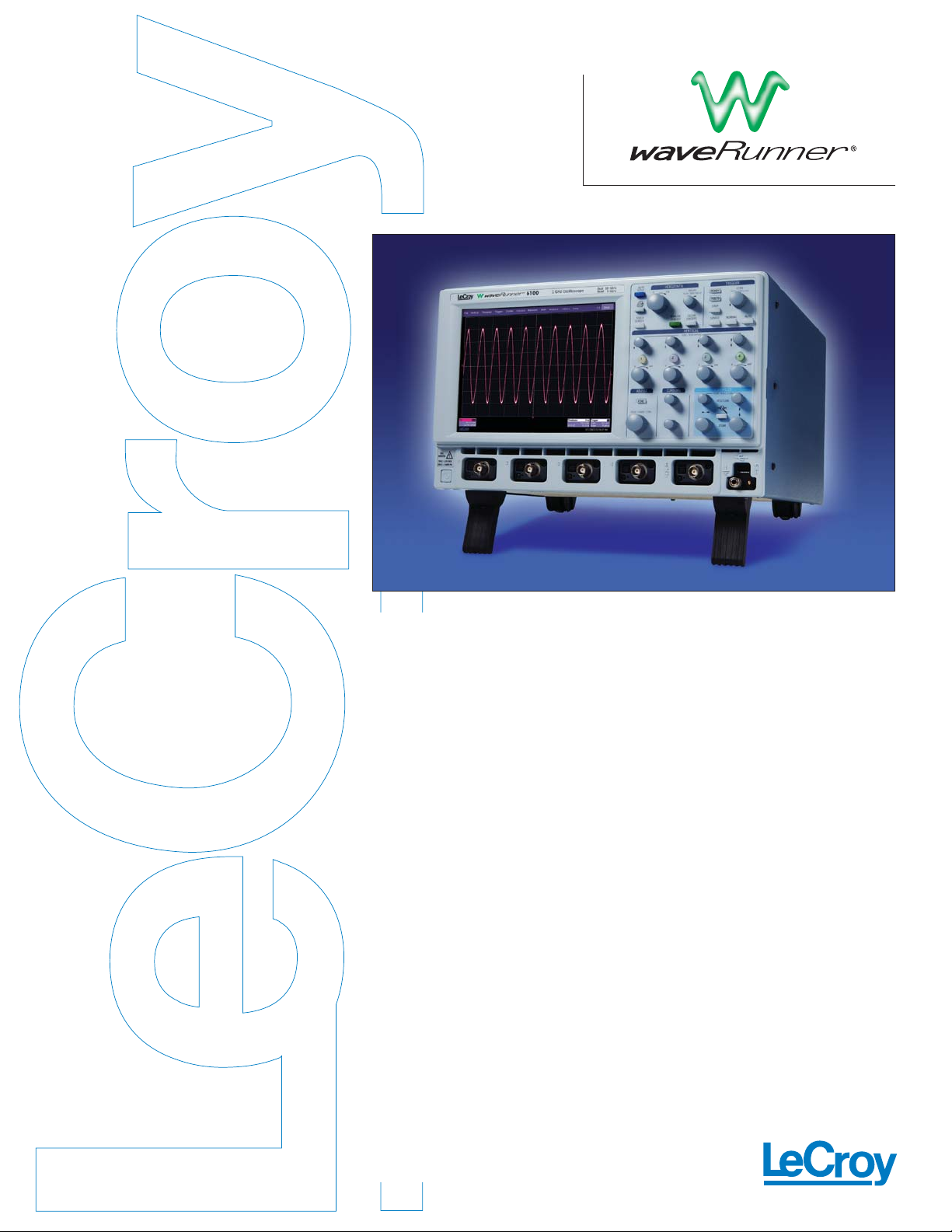
WaveRunner
6000 Series
6030
6050/6051
6100
6200
L
EADING FEATURES
• 350 MHz, 500 MHz, 1 GHz
and 2 GHz Bandwidths
• 5 GS/s on All Channels
(10 GS/s on 2 Ch for 6100 and 6200)
• 1 Mpts on All Channels,
Expandable to 12/24 Mpts
• Compact and Lightweight
• Easy User Interface
• New 2.5 mm Passive Probe
• Touch Screen Interface
• Ve rtical Controls for Each Channel
• USB 2.0 and 802.3xx LAN Ports
• Open Windows 2000
LeCroy’s WaveRunner
® 6000 Series is
built to be the world’s best everyday
bench oscilloscope. It offers the best
acquisition specifications, a user interface
that makes it easy to perform the most
common oscilloscope functions, industryleading long term support and a “feel”
that makes the oscilloscope a pleasure
to drive.
For the first time,LeCroy has combined
the type of high performance front
amplifier,ADC, memory and triggering
used in more expensive oscilloscopes
and designed it all into a very affordable
package. The WaveRunner 6000 Series
also introduces a user interface that
makes viewing and measuring signals
simple and fast.
With the WaveRunner 6000 Series, all
viewing controls and basic oscilloscope
functions are easily at hand using front
panel knobs. You get fast views and can
zoom in to see details on the bright touch
panel color screen. Or use the simple
and intuitive controls to call up exactly
the measurements you need.
The WaveRunner 6000 Series includes an
industry-leading signal acquisition path,
which provides a 5 GS/s ADC on every
channel and 1 Mbyte of standard memory.
No need to worry about the undersampling or aliasing caused by slower ADCs or
shorter memories on other oscilloscopes.
The WaveRunner 6000 Series comes
standard with the new PP007 500 MHz
passive probe (one per channel). This
2.5 mm high impedance probe offers
excellent characteristics for probing everyday signals. LeCroy also offers a wide
range of optional single-ended and
differential active probes, current probes,
optical to electrical (O/E) converters
and differential amplifiers.
Lastly,we decided to architect the
oscilloscope so that users could add just
the functionality they want. There are
options for testing power devices,serial
data mask testing, jitter and timing
analysis, and for a wide variety of probes,
O/E converters and other application
specific devices.
Altogether,the WaveRunner 6000 Series
sets a new industry standard for high
performance at low price in everyday
bench oscilloscopes.
Excellent Performance, Great Price, Easy to Use
Page 2

WaveRunner WaveRunner WaveRunner WaveRunner WaveRunner
Ver tical System 6030 6050 6051 6100 6200
Analog Bandwidth @ 50 Ω, 350 MHz 500 MHz 500 MHz 1 GHz 2 GHz
10 mV–1 V/div,(-3 dB)
Rise Time (Typical) 1 ns 750 ps 750 ps 400 ps 225 ps
Input Channels 44244
Bandwidth Limiters 20 MHz; 200 MHz
Input Impedance 1MΩ || < 20 pF (10 MΩ || 9.5 pF using PP007 probe)
Input Coupling 50 Ω: DC, 1MΩ:AC,DC,GND
Maximum Input Voltage 50 Ω:5 Vrms,1 MΩ: 250 Vmax (Peak AC: ≤ 5 kHz + DC)
Channel to Channel Isolation > 40 dB @ < 100MHz (> 30 dB @ full bandwidth)
Vertical Resolution 8 bits; up to 11 with enhanced resolution (ERES)
Sensitivity 50 Ω:2 mV/div—1 V/div fully variable; 1 MΩ:2 mV—10 V/div fully variable
DC Gain Accuracy ±1.0% of full scale (typical), ±1.5% of full scale with V/Div ≥ 10 mV (warranted)
Offset Range 50 Ω:±400 mV @ 2–4.95 mV/div
±1 V @ 5–100 mV/div
±10 V @ 102 mV/div – 1V/div
1 MΩ:±400 mV @ 2–4.95 mV/div
±1 V @ 5–100 mV/div
±10 V @ 102 mV/div – 1V/div
±100 V @ 1.02V/div – 10V/div
Offset Accuracy ±(1.5% + 0.5% of offset value +1 mV)
Probing System BNC or Probus®
Timebase System
Timebases Internal timebase common to all input channels; an external clock may be applied at the auxiliary input
Time/Division Range Real time: 200 ps/div—10 s/div, RIS mode: to 20 ps/div, Roll mode: up to 1,000 s/div
Clock Accuracy ≤ 5 ppm @ 25 °C (≤ 10 ppm @ 5–40 °C)
Time Interval Accuracy Clock Accuracy + Jitter Noise Floor
Sample Rate and Delay Time Accuracy Equal to Clock Accuracy
Trigger and Interpolator Jitter ≤ 3 ps rms
Channel to Channel Deskew Range ±9 X time/div setting, 100 ms max,each channel.
External Sample Clock DC to 1 GHz; 50 Ω or 1M Ω BNC input. Limited to 2 channel operation,(CH2 only in 6051).
Minimum rise time and amplitude requirements apply at low frequencies.
Roll Mode User selectable. Available at lower time/div settings.
Acquisition System
Single-Shot Sample Rate/Ch 2.5 GS/s 5 GS/s 5 GS/s 5 GS/s 5 GS/s
Interleaved Sample Rate (2 Ch) N/A N/A N/A 10 GS/s 10 GS/s
Max. Random Interleaved Sampling (RIS) Rate 200 GS/s
Max.Trigger Rate 125,000 waveforms/second
Sequence Time Stamp Resolution 1 ns
Minimum Time between Sequential Segments 8 µs
ACQUISITION MEMORY Max. Acquisition Points (4 Ch / 2 Ch;2 Ch / 1 Ch in 6051) Segments (Sequence Mode)
Standard 1M / 2M 500
Option S 2M / 4M 500
Option M 4M / 8M 1,000
Option L 8M / 16M 5,000
Option VL 12M / 24M 10,000
Acquisition Processing 6030 6050 6051 6100 6200
Time Resolution (min. Single-shot) 200 ps (5 GS/s) 100 ps (10 GS/s)
Averaged Summed and continuous averaging to 1 million sweeps
ERES From 8.5 to 11 bits vertical resolution
Envelope (Extrema) Envelope,Floor, or Roof for up to 1 million sweeps
Interpolation Linear or SinX/X
Trigger System
Trigger Modes Normal, Auto,Single, Stop
Sources Any input channel, External,Ext/10, or Line; slope and level unique to each source
Trigger Coupling DC
Pre-trigger Delay 0–100% of memory size (adjustable in 1% increments, or 100 ns)
Post-trigger Delay 10,000 divisions in real time mode, limited at slower time/div settings in roll mode.
Hold-off 2 ns to 20 s or 1 to 1,000,000,000 events
Internal Trigger Level Range ±4.1 div from center (typical)
6030 6050 6051 6100 6200
Trigger Sensitivity w/ Edge Trigger 2 div @ < 350 MHz; 2 div @ < 500 MHz; 2 div @ < 500 MHz; 2 div @ < 1 GHz 2 div @ < 2 GHz;
(CH1-4+ external) 1 div @ < 250 MHz 1 div @ < 350 MHz 1 div @ < 350 MHz 1 div @ < 750 MHz 1 div @ < 1.8 GHz
Max.Trigger Frequency w/ SMART Trigger® 350 MHz Max. 500 MHz Max. 500 MHz Max. 750 MHz Max. 750 MHz Max.
(CH1-4+ external) @ ≥ 10 mV @ ≥ 10 mV @ ≥ 10 mV @ ≥ 10 mV @ ≥ 10 mV
Trigger Level DC Accuracy ±4% full scale ±2 mV (typical)
External Trigger Range EXT/10 ±4V; EXT ±400mV
Basic Triggers
Edge/Slope/Line Triggers when signal meets slope (positive or negative) and level condition
SMART Triggers®
State or Edge Qualified Triggers on any input source only if a defined state or edge occurred on another input source.
Delay between sources is selectable by time or events.
Dropout Triggers if signal drops out for longer than selected time between 2 ns and 20 s.
Pattern Logic combination (AND, NAND,OR, NOR) of 5 inputs (4 channels and external trigger input — 2 Ch+EXT on 6051). Each source can be high,
low,or don’t care. The high and low level can be selected independently. Triggers at start or end of the pattern.
Specifications
Page 3

SMART Triggers®
with Exclusion Technology
Glitch and Pulse Width Triggers on positive or negative glitches with widths selectable from 600 ps to 20 s or on intermittent faults
(subject to bandwidth limit of oscilloscope).
Signal or Pattern Interval Triggers on intervals selectable between 2 ns and 20 s.
Timeout (State/Edge Qualified) Triggers on any source if a given state (or transition edge) has occurred on another source.
Delay between sources is 10 ns to 20 s,or 1 to 99,999,999 events.
Exclusion Triggering Trigger on intermittent faults by specifying the normal width or period.
Automatic Setup
Auto Setup Automatically sets timebase, trigger, and sensitivity to display a wide range of repetitive signals
Vertical Find Scale Automatically sets the vertical sensitivity and offset for the selected channels to display a waveform with maximum dynamic range.
Probes
Probes One PP007 per channel standard; Optional passive and active probes available
Probe System; Probus Automatically detects and supports a variety of compatible probes
Scale Factors Automatically or manually selected, depending on probe used
Color Waveform Display
Type Color 8.4" flat-panel TFT-LCD with high resolution touch screen
Resolution SVGA;800x600 pixels
Real Time Clock Dates,hours, minutes, seconds displayed with waveform. Accurate to ±50 ppm.SNTP support to synchronize to precision internet clocks.
Number of Traces Display a maximum of 8 traces. Simultaneously display channel,zoom,memory, and math traces.
Grid Styles Auto,Single, Dual,Quad, Octal, XY, Single + XY, Dual + XY
Waveform Styles Sample dots joined or dots only
Analog Persistence Display
Analog and Color-Graded Persistence Variable saturation levels;stores each trace’s persistence data in memory
Persistence Selections Select analog,color, or three-dimensional
Trace Selection Activate persistence on all or any combination of traces
Persistence Aging Time Select from 500 ms to infinity
Sweeps Displayed All accumulated,or all accumulated with last trace highlighted
Zoom Expansion Traces
Display up to 4 Zoom/Math traces.
CPU
Processor Intel Celeron 1.7 GHz or better
Processing Memory 256 MB on Std, S & M option;512 MB with L and VL option
Operating System Microsoft Windows 2000 Professional
Internal Waveform Memory
M1, M2,M3, M4 Internal Waveform Memory (store full-length waveform with 16 bits/data point) or
store to any number of files limited only by data storage media
Setup Storage
Front Panel and Instrument Status Store to the internal hard drive,over the network,or to a USB-connected peripheral device
Interface
Remote Control Via Windows Automation,or via LeCroy Remote Command Set
GPIB Port (Optional) Supports IEEE – 488.2
Ethernet Port 10/100Base-T Ethernet interface (RJ-45 connector)
USB Ports 5 USB 2.0 ports (one on front of instrument) supports Windows-compatible devices
External Monitor Port Standard 15-pin D-Type SVGA-compatible DB-15; connect a second monitor to use dual-monitor display mode
Parallel Port Standard DB-25
Serial Port DB-9 RS232 port (not for remote oscilloscope control)
Auxiliary Input
Signal Types Selected from External Trigger or External Clock input on front panel
Coupling 50 Ω: DC, 1MΩ:AC,DC,GND
Maximum Input Voltage 50 Ω:5 Vrms,1MΩ: 250 Vmax (Peak AC: ≤ 10 kHz + DC)
General
Auto Calibration Ensures specified DC and timing accuracy is maintained for 1-year minimum
Probe Calibrator Output available on front panel provides a variety of DC and square wave signals for probe compensation adjustment
Power 100–240 Vrms at 50/60 Hz; 115 Vrms (±10%) at 400 Hz Automatic AC Voltage Selection
Installation Category: 300V CAT II; Max. Power Consumption: 400 VA/400 W; 350 VA/350 W for WaveRunner 6051
Environmental
Temperature:Operating +5 °C to 40 °C
Temperature:Nonoperating –20 °C to +60 °C
Humidity: Operating 5% to 80% RH (noncondensing) up to 30 °C; upper limit derates linearly to 45% RH (noncondensing) at 40 °C
Humidity: Nonoperating 5% to 95% RH (noncondensing) as tested per MIL-PRF-28800F
Altitude: Operating 3,048 m (10,000 ft.) max at ≤ 25 °C
Altitude: Nonoperating 12,190m (40,000 ft.)
Physical
Dimensions (HWD) 211 mm x 355 mm x 363 mm (excluding handle and feet) 8.3" x 13.8" x 14.3"
Net Weight 10 kg (22 lbs.),excluding printer
Shipping Weight Less than 13.6 kg.(30 lbs.)
Certifications
CE Approved,UL and cUL listed;Conforms to EN 61326-1,EN 61010-1, UL 61010B-1, and CSA C22.2 No.1010.1
Warranty and Service
3-year warranty; calibration recommended annually.
Optional service programs include extended warranty, upgrades,calibration, and customization services
Specifications
Page 4

Sales and Service
Throughout
the World
Corporate Headquarters
700 Chestnut Ridge Road
Chestnut Ridge, NY 10977
USA
www.lecroy.com
LeCroy Sales Offices:
China: Beijing
Phone (86) 10 8526 1618
Fax (86) 10 8526 1619
France: Les Ulis
Phone (33) 1 6918 8320
Fax (33) 1 6907 4042
Germany: Heidelberg
Phone (49) 6221 827 00
Fax (49) 6221 834 655
Hong Kong
Phone (852) 2834 5630
Fax (852) 2834 9893
Italy: Venice
Phone (39) 041 599 7011
Fax (39) 041 456 9542
Japan: Osaka
Phone (81) 6 6396 0961
Fax (81) 6 6396 0962
Japan: Tokyo
Phone (81) 3 3376 9400
Fax (81) 3 3376 9587
Korea: Seoul
Phone (82) 2 3452 0400
Fax (82) 2 3452 0490
Singapore
Phone (65) 6442 4880
Fax (65) 6442 7811
Sweden: Stockholm
Phone (46) 8 580 143 45
Fax (46) 8 580 143 45
Switzerland: Geneva
Phone (41) 22 719 2228 (North)
Phone (41) 22 719 2175 (South)
Fax (41) 22 719 2230
U.K.: Abingdon
Phone (44) 1 235 536 973
Fax (44) 1 235 528 796
U.S.A.: Chestnut Ridge
Phone (1) 845 578 6020
Fax (1) 845 578 5985
WRUNNER_PDF
9/04 Rev 7
© 2004 by LeCroy Corporation. All rights reser ved.
LeCroy,ActiveDSO, ProBus,SMART Trigger, JitterTrack, WavePro, WaveMaster, and Waverunner are registered trademarks of LeCroy Corporation. Information in this publication supersedes all earlier versions. Specifications subject to change without notice.
WaveRunner 2- and 4-Channel Digital Oscilloscopes
2 GHz, 5 GS/s,1 Mpts/4 Ch; 10 GS/s, 2 Mpts/2 Ch,4 Ch Color WaveRunner 6200
1 GHz, 5 GS/s,1 Mpts/4 Ch; 10 GS/s, 2 Mpts/2 Ch,4 Ch Color WaveRunner 6100
500 MHz, 5 GS/s,1 Mpts/4 Ch; 5 GS/s, 2 Mpts/2 Ch,4 Ch Color WaveRunner 6050
500 MHz, 5 GS/s,1 Mpts/2 Ch; 5 GS/s, 2 Mpts/1 Ch,2 Ch Color WaveRunner 6051
350 MHz, 5 GS/s,1 Mpts/4 Ch; 5 GS/s, 2 Mpts/2 Ch,4 Ch Color WaveRunner 6030
Included with Standard Configuration
10:1 10 MΩ, 500 MHz BW Passive Probes – Qty 4 (2 with WaveRunner 6051) PP007
Printed Getting Started Manual WR6-GS-E
CD-ROM containing Operators Manual, Remote Command Manual, Utility Software, and Recovery Software
Optical 3-button Wheel Mouse – USB
Standard Ports; 10/100Base-T Ethernet,USB (5),Parallel,RS-232, SVGA Video out, Audio in/out
Internal Hard Drive
Protective Front Cover
Standard Commercial Calibration and Performance Certificate
3-Year Warranty
Memory Options 6200 6100 6050 6030 6051
2 Mpts/Ch, 4 Mpts maximum using 2 Channel (1 Channel for 6051) S S2
4 Mpts/Ch, 8 Mpts maximum using 2 Channel (1 Channel for 6051) M M2
8 Mpts/Ch, 16 Mpts maximum using 2 Channel (1 Channel for 6051) L L2
12 Mpts/Ch, 24 Mpts maximum using 2 Channel (1 Channel for 6051) VL VL2
Hardware Options
Removable HDD WR6-RHD
CD-RW Upgrade WR6-CDRW
WaveShape Analysis Packages
CAN Bus Tigger and Decode Test Package CANbus TD
Jitter and Timing Analysis WR6-JTA2
PowerMeasure Analysis WR6-PMA2
Disk Drive Measurement Package WR6-DDM2
Digital Filter Package WR6-DFP2
Serial Data Mask Package WR6-SDM
Ethernet Test Package (WaveRunner 6100 and 6200 only1) WR6-ENET
USB 2.0 Compliance Software (WaveRunner 6200 only2) WR6-USB2
Advanced Math Package WR6-XMATH
Intermediate Math Package WR6-XWAV
Master Analysis Package (XMATH + XDEV + JTA2) WR6-XMAP
Value Analysis Package (XWAV + JTA2) WR6-XVAP
Developer’s Customization Kit WR6-XDEV
Norton Antivirus WR6-AV
Selected Accessories
Passive Probe, 500 MHz PP007-1
2.5 GHz Active Voltage Probe HFP2500
1.5 GHz Active Voltage Probe HFP1500
1 GHz Active Voltage Probe HFP1000
500 MHz Differential Probe AP033
1 GHz Differential Probe AP034
500A, 2 MHz Current Probe CP500
150A, 10 MHz Current Probe CP150
15A, 50 MHz Current Probe CP015
30A, 50 MHz Current Probe AP015
3 GHz Differential Probe and Adjustable Tips D300 & D300AT
100 MHz Differential Amp DA1855A
Floppy Drive (External USB) WR6-FLPY
Rackmount, 6U Height WR6-RACK
Mini Keyboard WR6-KBD
Soft Carrying Case WR6-SOFT
Hard Transit Case WR6-HARD
Accessory Pouch WR6-POUCH
GPIB WR6-GPIB
256 MB USB Memory Key MEM-USB
Scope Cart – Basic OC1021
Scope Cart – With extra shelf & drawer OC1024
Operator’s Manual Printed Hardcopy WR6-OM-E
5-Year NIST Calibration and Warranty WR6-T5
1
Package may be used with lower BW oscilloscope models,however, some measurements will not operate with signals at all data rates.
2
Can be used with lower bandwidth models,however only USB 1.1 test functions will be available. WaveRunner 6200 required for USB 2.0 capability.
Ordering Information
 Loading...