

LeCroy 6000 SERIES, WAVERUNNER 6000 SERIES Operator's Manual

L
L
E
E
C
C
R
R
O
O
Y
Y
W
W
A
A
V
V
E
E
R
R
U
U
N
N
N
N
E
E
R
R
®
®
6600000
0
SSE
E
R
RII
E
ESS
O
O
SSC
CII
L
L
L
L
O
OSS
C
C
O
O
P
P
E
ESS
O
OPPEERRAATT
O
ORR’’SS
M
MAANNUUAALL
O
O
CCTTOOBBEERR
22000033

LeCroy Corporation
700 Chestnut Ridge Road
Chestnut Ridge, NY 10977 –6499
Tel: (845) 578 6020, Fax: (845) 578 5985
Internet: www.lecroy.com
© 2003 by LeCroy Corporation. All right s reserved.
LeCroy, ActiveDSO, ProBus, SMART Trigger, JitterTrack, WavePro, and Waverunner are
registered trademarks of LeCroy Corporation. WaveMaster and X-Stream are trademarks of
LeCroy Corporation. Information in this publication supersedes all earlier versions. Specifications
subject to change without notice.
WR6K-OM-E Rev A
901769-00

INTRODUCTION.................................................................................................14
HOW TO USE ON-LINE HELP....................................................................................................14
Type Styles ............................................................................................................................. 14
Instrument Help....................................................................................................................... 14
Windows Help ................................................................................................................................ 15
RETURNING A PRODUCT FOR SERVICE OR REPAIR ........................................................... 15
TECHNICAL SUPPORT................................................................................................................ 15
STAYING UP-TO-DATE................................................................................................................ 16
SPECIFICATIONS ........................................................................................................................ 17
Horizontal System .......................................................................................................................... 18
Acquisition System.........................................................................................................................19
Acquisition Modes ..........................................................................................................................19
Acquisition Processing ................................................................................................................... 20
Triggering System .......................................................................................................................... 20
Basic Triggers ................................................................................................................................20
SMART Triggers.............................................................................................................................20
SMART Triggers with Exclusion Technology.................................................................................. 21
Automatic Setup.............................................................................................................................21
Probes............................................................................................................................................21
Color Waveform Display.................................................................................................................21
Analog Persistence Display ...........................................................................................................22
Zoom Expansion Traces ................................................................................................................ 22
Rapid Signal Processing................................................................................................................22
Internal Waveform Memory............................................................................................................ 22
Setup Storage ................................................................................................................................22
Interface ......................................................................................................................................... 22
Auxiliary Input................................................................................................................................. 22
Auxiliary Output..............................................................................................................................23
Math Tools (standard).....................................................................................................................23
Measure Tools (standard) ..............................................................................................................24
Pass/Fail Testing ............................................................................................................................24
Master Analysis Package (XMAP) ................................................................................................. 24
Advanced Math Package (XMATH) ...............................................................................................25
Advanced Customization Package (XDEV)................................................................................... 25
Intermediate Math Package (XWAV) .............................................................................................25
Jitter and Timing Analysis Package (JTA2) .................................................................................... 26
Value Analysis Package (XVAP) ....................................................................................................26
Disk Drive Measurement Package (DDM2) ................................................................................... 27
General...........................................................................................................................................27
WR6K-OM-E Rev A ISSUED: October 2003 1

Operator's Manual
Warranty and Service.....................................................................................................................28
Environmental Characteristics .......................................................................................................28
Temperature ...........................................................................................................................28
Humidity .................................................................................................................................. 28
Altitude ....................................................................................................................................28
Random Vibration ................................................................................................................... 28
Shock ......................................................................................................................................28
Certifications ........................................................................................................................29
CE Declaration of Conformity .................................................................................................29
Warning................................................................................................................................ 29
WARRANTY................................................................................................................................... 30
COPYRIGHT ..................................................................................................................................31
SAFETY REQUIREMENTS...........................................................................................................39
Safety Symbols and Terms..................................................................................................... 39
Operating Environment ..................................................................................................................40
Cooling Requirements....................................................................................................................41
AC Power Source........................................................................................................................... 41
Power and Ground Connections....................................................................................................41
On/Standby Switch.........................................................................................................................42
Calibration ......................................................................................................................................42
Cleaning .........................................................................................................................................42
Abnormal Conditions......................................................................................................................43
FRONT PANEL CONTROLS.........................................................................................................43
Front Panel Buttons and Knobs.............................................................................................. 43
Trigger Knobs: ........................................................................................................................45
Trigger Buttons: ......................................................................................................................45
Horizontal Knobs:.................................................................................................................... 45
Vertical Knobs:........................................................................................................................ 46
Channel Buttons: ....................................................................................................................46
Wavepilot Control Knobs: ......................................................................................................46
Special Features Buttons:......................................................................................................46
General Control Buttons: .......................................................................................................46
ON-SCREEN TOOLBARS, ICONS, AND DIALOG BOXES......................................................47
Dialog Boxes ..................................................................................................................................48
ALTERNATE ACCESS METHODS ...............................................................................................48
Mouse and Keyboard Operation............................................................................................. 48
Tool Bar Buttons ..................................................................................................................... 49
TRACE DESCRIPTORS................................................................................................................ 50
Trace Annotation ............................................................................................................................50
To Annotate a Waveform........................................................................................................ 51
To Turn On a Channel Trace Label ................................................................................................52
2 ISSUED: October 2003 WR6K-OM-E Rev A

SCREEN LAYOUT.........................................................................................................................53
INSTALLATION..................................................................................................55
Hardware........................................................................................................................................ 55
External Monitor ............................................................................................................................. 55
WRITABLE CD DRIVE OPTION.......................................................................................... 56
Software .........................................................................................................................................59
Checking the Scope Status .................................................................................................... 59
DEFAULT SETTINGS ...................................................................................................................60
WaveMaster and WavePro 7000 Series DSOs...................................................................... 60
DDA, SDA, and WaveRunner DSOs..............................................................................................60
ADDING A NEW OPTION ........................................................................................................... 61
RESTORING SOFTWARE............................................................................................................ 62
Restarting the Application....................................................................................................... 62
Restarting the Operating System............................................................................................ 62
REMOVABLE HARD DRIVE ........................................................................................................ 62
EXTERNAL MONITOR ................................................................................................................. 64
CONNECTING TO A SIGNAL ............................................................................66
PROBUS INTERFACE...................................................................................................................66
AUXILIARY OUTPUT SIGNALS.................................................................................................. 67
To Set Up Auxiliary Output .............................................................................................................67
SAMPLING MODES ...........................................................................................68
SAMPLING MODES .....................................................................................................................68
To Select a Sampling Mode.................................................................................................... 68
SINGLE-SHOT SAMPLING MODE.............................................................................................68
Basic Capture Technique ....................................................................................................... 68
SEQUENCE SAMPLING MODE WORKING WITH SEGMENTS.............................................. 69
To Set Up Sequence Mode .................................................................................................... 70
Sequence Display Modes ....................................................................................................... 71
To Display Individual Segments .............................................................................................72
To View Time Stamps.............................................................................................................72
RIS SAMPLING MODE -- FOR HIGHER SAMPLE RATES ......................................................73
ROLL MODE.................................................................................................................................. 74
VERTICAL SETTINGS AND CHANNEL CONTROLS .......................................75
ADJUSTING SENSITIVITY AND POSITION ............................................................................75
To Adjust Sensitivity................................................................................................................ 75
To Adjust the Waveform's Position......................................................................................... 75
COUPLING ....................................................................................................................................75
Overload Protection ................................................................................................................ 75
To Set Coupling ...................................................................................................................... 76
PR OBE ATTENUATION ................................................................................................................76
WR6K-OM-E Rev A ISSUED: October 2003 3

Operator's Manual
To Set Probe Attenuation ....................................................................................................... 76
BANDWIDTH LIMIT.....................................................................................................................76
To Set Bandwidth Limiting ......................................................................................................76
LINEAR AND (SINX)/X INTERPOLATION................................................................................77
To Set Up Interpolation........................................................................................................... 77
Inverting Waveforms............................................................................................................... 77
QUICKZOOM ................................................................................................................................77
To Turn On a Zoom ................................................................................................................77
FINDING SCALE ..........................................................................................................................77
To Use Find Scale ..................................................................................................................77
VARIABLE GAIN...........................................................................................................................77
To Enable Variable Gain.........................................................................................................78
CHANNEL DESKEW.....................................................................................................................78
To Set Up Channel Deskew ................................................................................................... 78
TIMEBASE AND ACQUISITION SYSTEM.........................................................79
TIMEBASE SETUP AND CONTROL ...........................................................................................79
DUAL CHANNEL ACQUISITION ................................................................................................79
Combining of Channels...........................................................................................................79
To Combine Channels ............................................................................................................79
AUTOSETUP..................................................................................................................................80
TRIGGERING .....................................................................................................81
TRIGGER SETUP CONSIDERATIONS....................................................................................... 81
Trigger Modes.........................................................................................................................81
Trigger Types..........................................................................................................................81
Determining Trigger Level, Slope, Source, and Coupling..............................................................82
Trigger Source................................................................................................................................83
Level...............................................................................................................................................83
Holdoff by Time or Events ..............................................................................................................84
Hold Off by Time ..................................................................................................................... 84
Hold Off by Events .................................................................................................................. 85
SIMPLE TRIGGERS .....................................................................................................................85
Edge Trigger on Simple Signals ............................................................................................. 85
Control Edge Triggering.......................................................................................................... 85
To Set Up an Edge Trigger..................................................................................................... 86
SMART TRIGGERS ......................................................................................................................89
WIDTH TRIGGER........................................................................................................................ 89
GLITCH TRIGGER....................................................................................................................... 90
INTERVAL TRIGGER ................................................................................................................... 92
QUALIFIED TRIGGER .................................................................................................................. 96
STATE TRIGGER ........................................................................................................................ 99
DROPOUT TRIGGER................................................................................................................. 100
LOGIC TRIGGER ...................................................................................................................... 101
4 ISSUED: October 2003 WR6K-OM-E Rev A

DISPLAY FORMATS........................................................................................104
DISPLAY SETUP.........................................................................................................................104
Sequence Mode Display....................................................................................................... 104
PERSISTENCE SETUP............................................................................................................... 105
Saturation Level.................................................................................................................... 105
3-Dimensional Persistence ................................................................................................... 106
Show Last Trace .......................................................................................................................... 107
Persistence Time..........................................................................................................................108
Locking of Traces.........................................................................................................................108
To Set Up Persistence..................................................................................................................108
SCREEN SAVER ......................................................................................................................... 109
MOVING TRACES FROM GRID TO GRID .............................................................................. 109
ZOOMING WAVEFORMS .......................................................................................................... 110
To Zoom a Single Channel ................................................................................................... 111
To Zoom by Touch-and-Drag ...............................................................................................111
To Zoom Multiple Waveforms Quickly.................................................................................. 112
Multi-Zoom ............................................................................................................................ 112
XY DISPLAY................................................................................................................................114
To Set Up XY Displays .........................................................................................................114
SAVE AND RECALL ........................................................................................115
SAVING AND RECALLING SCOPE SETTINGS ...................................................................... 115
To Save Scope Settings .......................................................................................................115
To Recall Scope Settings ..................................................................................................... 115
To Recall Default Settings .................................................................................................... 115
SAVING SCREEN IMAGES....................................................................................................... 116
SAVING AND RECALLING WAVEFORMS............................................................................... 116
Saving Waveforms................................................................................................................ 116
Recalling Waveforms............................................................................................................ 118
DISK UTILITIES ........................................................................................................................ 118
To Delete a Single File .........................................................................................................118
To Delete All Files in a Folder............................................................................................... 119
To Create a Folder................................................................................................................ 119
PRINTING AND FILE MANAGEMENT.............................................................120
PRINT, PLOT, OR COPY.............................................................................................................120
PRINTING ...................................................................................................................................120
To Set Up the Printer ............................................................................................................ 120
To Print .................................................................................................................................120
Adding Printers and Drivers.................................................................................................. 120
Changing the Default Printer ................................................................................................ 121
MANAGING FILES .....................................................................................................................121
Hard Disk Partitions .............................................................................................................. 121
WR6K-OM-E Rev A ISSUED: October 2003 5

Operator's Manual
100BASE-T ETHERNET CONNECTION .........................................................122
CONNECTING TO A NETWORK...............................................................................................122
COMMUNICATING OVER THE NETWORK .............................................................................123
Windows Setups ................................................................................................................... 123
Windows Repair Disk............................................................................................................123
TRACK VIEWS.................................................................................................124
CREATING AND VIEWING A TREND......................................................................................124
CREATING A TRACK VIEW ......................................................................................................125
HISTOGRAMS..................................................................................................126
CREATING AND VIEWING A HISTOGRAM............................................................................126
To Set Up a Single Parameter Histogram ............................................................................126
To View Thumbnail Histograms............................................................................................ 127
Persistence Histogram..........................................................................................................127
Persistence Trace Range .....................................................................................................128
Persistence Sigma ................................................................................................................ 128
HISTOGRAM PARAMETERS ..................................................................................................... 128
HISTOGRAM THEORY OF OPERATION..................................................................................143
DSO Process ........................................................................................................................ 144
Parameter Buffer................................................................................................................... 145
Capture of Parameter Events ............................................................................................... 145
Histogram Parameters (XMAP and JTA2 Options) ...................................................................... 146
Histogram Peaks..........................................................................................................................147
Binning and Measurement Accuracy ........................................................................................... 147
WAVEFORM MEASUREMENTS .....................................................................149
MEASURING WITH CURSORS ................................................................................................ 149
Cursor Measurement Icons .................................................................................................. 149
CURSORS SETUP ...................................................................................................................... 149
Quick Display ........................................................................................................................ 149
Full Setup.............................................................................................................................. 150
OVERVIEW OF PARAMETERS..................................................................................................150
To Turn On Parameters........................................................................................................ 150
Quick Access to Parameter Setup Dialogs........................................................................... 150
Status Symbols ..................................................................................................................... 151
Using X-Stream Browser to Obtain Status Information ........................................................ 152
Statistics .......................................................................................................................................153
To Apply a Measure Mode............................................................................................................154
Measure Modes ...........................................................................................................................154
Standard Vertical Parameters............................................................................................... 154
Standard Horizontal Parameters ..........................................................................................155
My Measure .......................................................................................................................... 155
Parameter Math (XMATH or XMAP option required) ................................................................... 155
6 ISSUED: October 2003 WR6K-OM-E Rev A

Logarithmic Parameters........................................................................................................ 155
Excluded Parameters ........................................................................................................... 156
Parameter Script Parameter Math........................................................................................ 156
Param Script vs. P Script...................................................................................................... 157
To Set Up Parameter Math................................................................................................... 158
To Set Up Parameter Script Math......................................................................................... 158
Measure Gate ..............................................................................................................................159
To Set Up Measure Gate...................................................................................................... 161
Help Markers................................................................................................................................162
To Set Up Help Markers .......................................................................................................163
To Turn Off Help Markers ..................................................................................................... 164
To Customize a Parameter...........................................................................................................164
From the Measure Dialog ..................................................................................................... 164
From a Vertical Setup Dialog................................................................................................ 164
From a Math Setup Dialog.................................................................................................... 165
PARAMETER CALCULATIONS ..................................................................................................166
Parameters and How They Work.......................................................................................... 166
Determining Time Parameters.............................................................................................. 168
Determining Differential Time Measurements ...................................................................... 169
Level and Slope .................................................................................................................... 169
LIST OF PARAMETERS .............................................................................................................170
WAVEFORM MATH..........................................................................................194
INTRODUCTION TO MATH TRACES AND FUNCTIONS ......................................................194
MATH MADE EASY.....................................................................................................................194
To Set Up a Math Function................................................................................................... 194
RESAMPLING TO DESKEW...................................................................................................... 195
To Resample......................................................................................................................... 195
RESCALING AND ASSIGNING UNITS ...................................................................................196
To Set Up Rescaling............................................................................................................. 196
AVERAGING WAVEFORMS.......................................................................................................196
Summed vs. Continuous Averaging .....................................................................................196
To Set Up Continuous Averaging ......................................................................................... 198
To Set Up Summed Averaging ............................................................................................. 198
ENHANCED RESOLUTION .......................................................................................................199
How the Instrument Enhances Resolution ........................................................................... 199
To Set Up Enhanced Resolution (ERES)..................................................................................... 201
WAVEFORM COPY .....................................................................................................................202
WAVEFORM SPARSER ..............................................................................................................202
To Set Up Waveform Sparser............................................................................................... 202
INTERPOLATION........................................................................................................................203
To Set Up Interpolation......................................................................................................... 203
FFT...............................................................................................................................................203
WHY USE FFT? ................................................................................................................... 203
WR6K-OM-E Rev A ISSUED: October 2003 7

Operator's Manual
Improving Dynamic Range...........................................................................................................206
Record Length.............................................................................................................................. 207
FFT ALGORITHMS.............................................................................................................. 207
GLOSSARY .......................................................................................................................... 209
FFT SETUP........................................................................................................................... 212
ANALYSIS........................................................................................................214
PASS/FAIL TESTING.................................................................................................................214
COMPARING PARAMETERS ...................................................................................................... 214
MASK TESTS........................................................................................................................... 215
Actions .................................................................................................................................. 215
Setting Up Pass/Fail Testing ........................................................................................................216
Initial Setup ........................................................................................................................... 216
Comparing a Single Parameter ............................................................................................217
Comparing Dual Parameters ................................................................................................ 218
Mask Testing......................................................................................................................... 219
UTILITIES.........................................................................................................221
STATUS .......................................................................................................................................221
To Access Status Dialog....................................................................................................... 221
REMOTE COMMUNICATION..................................................................................................... 221
To Set Up Remote Communication. ..................................................................................... 221
To Configure the Remote Control Assistant Event Log........................................................222
HARDCOPY .................................................................................................................................222
PRINTING................................................................................................................................ 222
CLIPBOARD ............................................................................................................................. 222
FILE........................................................................................................................................ 222
E-MAIL ...................................................................................................................................223
AUX OUTPUT..............................................................................................................................224
DATE & TIME..............................................................................................................................224
To Set Time and Date Manually ........................................................................................... 224
To Set Time and Date from the Internet ............................................................................... 224
To Set Time and Date from Windows................................................................................... 224
OPTIONS.....................................................................................................................................225
PREFERENCES ...........................................................................................................................225
Audible Feedback ................................................................................................................. 225
Auto-calibration ..................................................................................................................... 226
Offset Control........................................................................................................................226
Delay Control ........................................................................................................................ 226
Performance Optimization ....................................................................................................226
E-mail.................................................................................................................................... 227
ACQUISITION STATUS.............................................................................................................227
SERVICE ..................................................................................................................................... 228
SHOW WINDOWS DESKTOP...................................................................................................228
8 ISSUED: October 2003 WR6K-OM-E Rev A

TOUCH SCREEN CALIBRATION .............................................................................................. 228
CUSTOMIZATION ............................................................................................229
CUSTOMIZING YOUR INSTRUMENT .....................................................................................229
Introduction ........................................................................................................................... 229
Solutions ............................................................................................................................... 229
Examples .............................................................................................................................. 230
What is Excel? ...................................................................................................................... 235
What is Mathcad? ................................................................................................................. 235
What is MATLAB?................................................................................................................. 235
What is VBS?........................................................................................................................235
What can you do with a customized instrument? ................................................................. 237
CALLING EXCEL FROM YOUR INSTRUMENT........................................................................238
Calling Excel Directly from the Instrument............................................................................ 238
How to Select a Math Function Call.............................................................................................239
How to Select a Parameter Function Call .................................................................................... 239
The Excel Control Dialog .............................................................................................................239
Entering a File Name ...................................................................................................................239
Organizing Excel sheets ..............................................................................................................241
Setting the Vertical Scale.............................................................................................................242
Trace Descriptors.........................................................................................................................242
Multiple Inputs and Outputs .........................................................................................................243
Simple Excel Example 1 ....................................................................................................... 243
Simple Excel Example 2 ....................................................................................................... 247
Examples of Excel Parameter Functions ..................................................................................... 250
Examples of Excel Waveform Functions......................................................................................251
Exponential Decay Time Constant Excel Parameter (Excel Example 1).....................................251
Gated Parameter Using Excel (Excel Example 2) .......................................................................253
How Does this Work? ...........................................................................................................254
Correlation Excel Waveform Function (Excel Example 3) ........................................................... 255
Multiple Traces on One Grid (Excel Example 4).......................................................................... 257
Using a Surface Plot (Excel Example 5) ...................................................................................... 260
WRITING VB SCRIPTS ............................................................................................................. 262
Types of Scripts in VBS ........................................................................................................262
Loading and Saving VBScripts ............................................................................................. 262
The default parameter function script: explanatory notes .................................................... 266
Scripting with VBScript .........................................................................................................267
Variable Types...................................................................................................................... 268
Variable Names ............................................................................................................................ 268
Arithmetic Operators ....................................................................................................................270
VBS Controls................................................................................................................................ 272
IF . . . Then . . . Else . . . End If ............................................................................................. 272
Summary of If . . . . Then . . . . Else ...................................................................................... 274
Select Case........................................................................................................................... 275
WR6K-OM-E Rev A ISSUED: October 2003 9

Operator's Manual
Summary of Select Case . . . . End Select ........................................................................... 276
Do . . . Loop ..........................................................................................................................276
While . . . Wend..................................................................................................................... 277
For . . . Next .......................................................................................................................... 277
VBS keywords and functions .......................................................................................................278
Other VBS Words .................................................................................................................280
Functions......................................................................................................................................280
Hints and Tips for VBScripting .....................................................................................................281
ERRORS......................................................................................................................................283
Error Handling ..............................................................................................................................285
Speed of Execution ...................................................................................................................... 285
Scripting Ideas..............................................................................................................................286
Example Waveform Script............................................................................................................286
Example Parameter Scripts .........................................................................................................287
Debugging Scripts........................................................................................................................287
Horizontal Control Variables.........................................................................................................287
Vertical Control Variables .............................................................................................................288
List of Variables Available to Scripts ............................................................................................288
Communicating with Excel from a VBScript................................................................................. 290
CALLING MATLAB FROM THE INSTRUMENT........................................................................291
Calling MATLAB.................................................................................................................... 291
How to Select a Waveform Function Call.....................................................................................292
The MATLAB Waveform Control Panel........................................................................................293
MATLAB Waveform Function Editor -- Example..........................................................................293
MATLAB Example Waveform Plot................................................................................................297
How to Select a MATLAB Parameter Call.................................................................................... 298
The MATLAB Parameter Control Panel .......................................................................................299
The MATLAB Parameter Editor....................................................................................................300
MATLAB Example Parameter Panel ............................................................................................ 301
Further Examples of MATLAB Waveform Functions....................................................................303
Creating your own MATLAB function ...........................................................................................306
CUSTOMDSO...................................................................................................307
CUSTOM DSO ............................................................................................................................307
Introduction – What is CustomDSO?.................................................................................... 307
Invoking CustomDSO ...........................................................................................................307
CustomDSO Basic Mode...................................................................................................... 308
Editing a CustomDSO Setup File .........................................................................................308
Creating a CustomDSO Setup File....................................................................................... 310
CustomDSO PlugIn Mode ....................................................................................................310
Creating a CustomDSO PlugIn............................................................................................. 310
Properties of the Control and its Objects.............................................................................. 312
Removing a PlugIn................................................................................................................ 316
First Example PlugIn – Exchanging Two Traces on the Grids ............................................. 316
10 ISSUED: October 2003 WR6K-OM-E Rev A

Second Example PlugIn – Log-Log FFT Plot ....................................................................... 319
Control Variables in CustomDSO ......................................................................................... 322
JTA2 OPTION...................................................................................................323
ACCESSING JTA2...................................................................................................................... 323
TIMING FUNCTIONS.................................................................................................................323
TIMING PARAMETERS.............................................................................................................. 324
Statistical Tools..................................................................................................................... 324
HOW JITTERTRACK WORKS ................................................................................................... 324
Using “Clock” or “Data” .........................................................................................................324
WHEN TO USE JITTERTRACK .................................................................................................327
JitterTrack or Trend? ............................................................................................................ 327
CLOCK OR DATA?...................................................................................................................... 329
SETTING UP JITTER MEASUREMENTS ..................................................................................331
Jitter Math Setup................................................................................................................... 331
Jitter Parameters Setup ........................................................................................................331
WHEN TO USE PERSISTENCE HISTOGRAMS......................................................................331
SETTING UP PERSISTENCE HISTOGRAMS .......................................................................... 332
Selecting the Math Function ................................................................................................. 332
Setting Up the Histogram...................................................................................................... 333
HOW TO TRACE PERSISTENCE.............................................................................................. 334
An Innovative Visual and Processing Tool ...........................................................................334
To Set Up Trace Persistence........................................................................................................335
CHOOSING A TIMING PARAMETER....................................................................................... 337
HOW TO USE THE TREND TOOL............................................................................................ 337
The Basic Idea ...................................................................................................................... 337
To Set Up and Configure Trend............................................................................................ 338
Math Setup............................................................................................................................ 341
HISTOGRAM AND TREND CALCULATION............................................................................. 341
Acquisition Sequence ........................................................................................................... 341
Parameter Buffer................................................................................................................... 342
Parameter Events Capture ................................................................................................... 342
Zoom Traces and Segmented Waveforms...................................................................................343
Histogram Peaks................................................................................................................... 343
Example ................................................................................................................................ 343
Binning and Measurement Accuracy.................................................................................... 344
DFP2 OPTION ..................................................................................................347
INTRODUCTION ........................................................................................................................ 347
The Need .............................................................................................................................. 347
The Solution..........................................................................................................................347
Enhanced Solutions .....................................................................................................................348
KINDS OF FILTERS..................................................................................................................... 349
Communications Channel Filters ................................................................................................. 351
WR6K-OM-E Rev A ISSUED: October 2003 11

Operator's Manual
IIR Filters ......................................................................................................................................353
FILTER SETUP............................................................................................................................354
To Set Up a DFP Filter.......................................................................................................... 354
MULTIRATE FILTERS .................................................................................................................355
Description ............................................................................................................................ 355
CUSTOM FILTERS......................................................................................................................356
Custom Filter Setup .............................................................................................................. 356
Example 1: Creating an FIR Filter Coefficient File Using Mathcad ......................................356
Example 2: Creating an IIR Filter Coefficient File Using Mathcad ....................................... 358
SPECIFICATIONS ...................................................................................................................... 359
PMA2 OPTION .................................................................................................360
INTRODUCTION TO PMA2....................................................................................................... 360
The Tools and What They Do............................................................................................... 360
Equipment Required ............................................................................................................. 360
DESKEWING VOLTAGE AND CURRENT.................................................................................361
Matching the Time Delay in Your Measurement System .....................................................361
Initial Setup ........................................................................................................................... 363
Clearing the Deskew Setup .................................................................................................. 367
USING POWER DEVICE ANALYSIS ........................................................................................ 368
Setup and Configuration for Power Device Analysis ............................................................ 368
Initial Setup (Optional Event Trigger).................................................................................... 369
Initial Setup (Main Trigger) ...................................................................................................370
Setup for Power Device Analysis.......................................................................................... 371
Power Device Analysis Measurements ................................................................................373
Saturation Voltage and Dynamic On-resistance Measurement ...........................................377
Fine DC Level Adjustment ....................................................................................................379
Effects of Probe Compensation on Saturation Voltage Measurements.......................................379
Example: ............................................................................................................................... 380
Clearing the Power Device Analysis Setup .................................................................................. 382
Measuring Device dv/dt................................................................................................................382
To Access dv/dt ....................................................................................................................383
USING MODULATION ANALYSIS............................................................................................384
How Modulation Analysis Works ..........................................................................................384
The Modulation Analysis Display .................................................................................................387
Configuration for Modulation Analysis..........................................................................................387
Setup for Modulation Analysis Measurements.............................................................................388
Modulated Signal and Trigger Setup .................................................................................... 388
Trigger Setup – The Event Trigger ....................................................................................... 389
Initial Setup – The Modulated Signal.................................................................................... 390
Finishing the Setup and Making Modulation Measurements................................................ 390
Activating the Modulation Analysis Menu ............................................................................. 390
Modulation Analysis Controls .......................................................................................................391
Optimizing the Display .................................................................................................................392
12 ISSUED: October 2003 WR6K-OM-E Rev A

Clearing the Modulation Analysis Setup ......................................................................................392
USING LINE POWER ANALYSIS ............................................................................................. 393
Line Power Analysis Overview .............................................................................................393
EN 61000-3-2, Harmonic Current Emissions .......................................................................393
Configuration for Line Power Analysis ......................................................................................... 394
Setting Up the Line Voltage and Current Signals.........................................................................396
Activating the Line Power Analysis Menu............................................................................. 397
Line Harmonics Measurement .....................................................................................................398
USING NON-PROBUS PROBES...............................................................................................401
PMA2 Dialog Overview......................................................................................................... 401
Current Input Setup Menus................................................................................................... 402
Voltage Input Setup Menus ..................................................................................................403
PROCESSING WEB.........................................................................................404
PROCESSING WEB ................................................................................................................... 404
To Use the Web Editor ......................................................................................................... 404
WR6K-OM-E Rev A ISSUED: October 2003 13
Operator's Manual
INTRODUCTION
HOW TO USE ON-LINE HELP
Type Styles
Activators of pop-up text and images appear as green, underlined, italic: Pop-up
text and images after opening them, touch the pop-up text again.
Links jump you to other topics, URLs, or images. They take you out of the current Help screen.
Link text appears blue and underlined: Link
icon in the toolbar at the top of the Help window to return to the Help screen you just left. With
each touch of the Back icon, you return to the preceding Help screen.
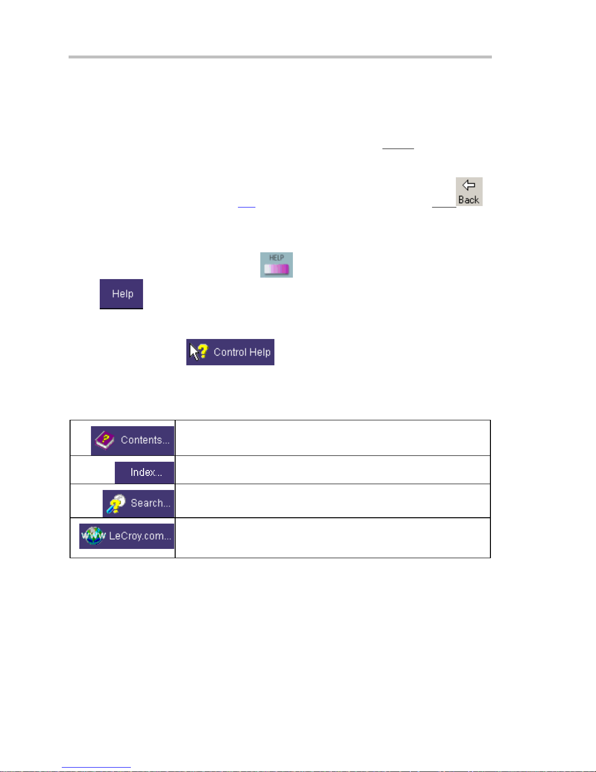
Instrument Help
When you press the front panel Help button
button
found for you automatically or to search for information yourself.
If you want context-sensitive Help, that is, Help related to what was displayed on the screen when
you requested Help, touch
control (or front panel button or knob) that you need information about. The instrument will
automatically display Help about that control.
If you want information about something not displayed on the screen, touch one of the buttons
inside the drop-down menu to display the on-line Help manual:
, you will be presented with a menu: you can choose either to have information
. After making a jump, you can touch the Back
(if available), or touch the on-screen Help
in the drop-down menu, then touch the on-screen
. To close pop-up
Contents displays the Table of Contents.
Index displays an alphabetical listing of keywords.
Search locates every occurrence of the keyword that you enter.
www.LeCroy.com connects you to LeCroy's Web site where you can
find Lab Briefs, Application Notes, and other useful information. This
feature requires that the instrument be connected to the internet through
14 ISSUED: October 2003 WR6K-OM-E Rev A

the Ethernet port on the scope's rear panel. Refer to Remote
Communication for setup instructions.
About opens the Utilities "Status" dialog, which shows software version
and other system information.
Once opened, the Help window will display its navigation pane: the part of the window that shows
the Table of Contents and Index. When you touch anywhere outside of the Help window, this
navigation pane will disappear to reveal more of your signal. To make it return, touch the Show
icon at the top of the Help window or touch inside the Help information pane.
Windows Help
In addition to instrument Help, you can also access on-line Help for Microsoft® Windows®. This
help is accessible by minimizing the scope application, then touching the Start button in the
Windows task bar at the bottom of the screen and selecting Help.
RETURNING A PRODUCT FOR SERVICE OR REPAIR
If you need to return a LeCroy product, identify it by its model and serial numbers. Describe the
defect or failure, and give us your name and telephone number.
For factory returns, use a Return Authorization Number (RAN), which you can get from customer
service. Write the number clearly on the outside of the shipping carton.
Return products requiring only maintenance to your local customer service center.
If you need to return your scope for any reason, use the original shipping carton. If this is not
possible, be sure to use a rigid carton. The scope should be packed so that it is surrounded by a
minimum of four inches (10 cm) of shock absorbent material.
Within the warranty period, transportation charges to the factory will be your responsibility.
Products under warranty will be returned to you with transport prepaid by LeCroy. Outside the
warranty period, you will have to provide us with a purchase order number before the work can be
done. You will be billed for parts and labor related to the repair work, as well as for shipping.
You should prepay return shipments. LeCroy cannot accept COD (Cash On Delivery) or Collect
Return shipments. We recommend using air freight.
TECHNICAL SUPPORT
You can get assistance with installation, calibration, and a full range of software applications from
your customer service center. Visit the LeCroy Web site at http://www.lecroy.com for the center
nearest you.
WR6K-OM-E Rev A ISSUED: October 2003 15

Operator's Manual
STAYING UP-TO-DATE
To maintain your instrument’s performance within specifications, have us calibrate it at least once
a year. LeCroy offers state-of-the-art performance by continually refining and improving the
instrument’s capabilities and operation. We frequently update both firmware and software during
service, free of charge during warranty.
You can also install new purchased software options in your scope yourself, without having to
return it to the factory. Simply provide us with your instrument serial number and ID, and the
version number of instrument software installed. We will provide you with a unique option key that
consists of a code to be entered through the Utilities' Options dialog to load the software option.
16 ISSUED: October 2003 WR6K-OM-E Rev A
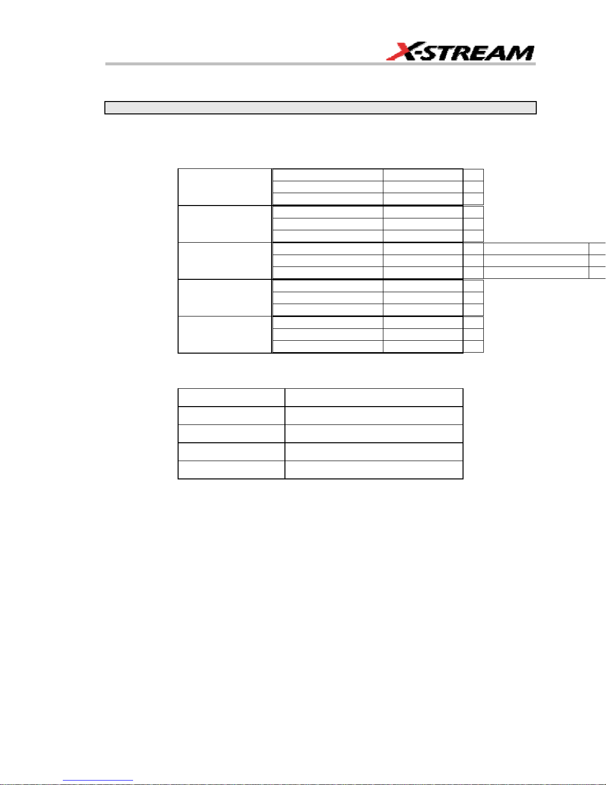
SPECIFICATIONS
Note: Specifications are subject to change without notice.
Vertical System
Bandwidth @ 50 ohms (-3 dB):
10 mV/div to 1 V/div 350 MHz
WaveRunner 6030
WaveRunner 6050
WaveRunner 6051
WaveRunner 6100
WaveRunner 6200
Input Channels: 4 (model 6051: 2)
5 mV/div to 9.95 m/div 350 MHz
2 mV/div to 4.99 m/div 300 MHz
10 mV/div to 1 V/div 500 MHz
5 mV/div to 9.95 m/div 500 MHz
2 mV/div to 4.99 m/div 350 MHz
10 mV/div to 1 V/div 500 MHz
5 mV/div to 9.95 m/div 500 MHz
2 mV/div to 4.99 m/div 350 MHz
10 mV/div to 1 V/div 1 GHz
5 mV/div to 9.95 m/div 800 MHz
2 mV/div to 4.99 m/div 350 MHz
10 mV/div to 1 V/div 2 GHz
5 mV/div to 9.95 m/div 1 GHz
2 mV/div to 4.99 m/div 350 MHz
Rise Time (typical):
WaveRunner 6030 1 ns
WaveRunner 6050 750 ps
WaveRunner 6051 750 ps
WaveRunner 6100 400 ps
WaveRunner 6200 225 ps
Bandwidth Limiters:
• Full
• 200 MHz
• 20 MHz
Input Impedance: 1 Mohms // < 20 pF (10 // 9.5 pF using PP007 probe)
WR6K-OM-E Rev A ISSUED: October 2003 17

Operator's Manual
Input Coupling: 50 ohms: DC; 1 Mohms: AC, DC, GND
Max Input Voltage: 50 ohms: 5 V
Installation (Overvoltage) Category: CAT I
Channel to Channel Isolation: > 40 dB @ < 100 MHz (> 30 dB @ full bandwidth)
Vertical Resolution: 8 bits; up to 11 bits with enhanced resolution (ERES)
Sensitivity: 50 ohms: 2 mV to 1 V/div fully variable; 1 Mohms: 2 mV to 10 V/div fully variable
DC Gain Accuracy: ±1.5% of full scale
Offset Range:
50 ohms ±400 mV @ 2.0 to 4.99 mV/div
1 Mohms ±500 mV @ 2.0 to 4.99 mV/div
Offset Accuracy: ±(1.5% of full scale value + 0.5% of offset value + 1 mV)
Probing System: BNC or ProBus
; 1 Mohms: 250 V
rms
±1.0 V @ 5 to 99 mV/div
±10 V @ 0.100 to 1 V/div
±1.0 V @ 5 to 99 mV/div
±10 V @ 0.100 to 1 V/div
±100 V @ 1 to 10 V/div
(Peak AC: ≤ 10 kHz + DC)
max
Horizontal System
Timebases: Internal timebase common to all input channels; an external clock can be applied at
the auxiliary input
Time/div Range: 20 ps/div to 10 s/div
Math & Zoom Traces: 4 math/zoom traces standard
Clock Accuracy: ≤ 5 ppm at 25 °C (≤ 10 ppm at 5 to 40 °C)
Jitter Noise Floor: 2 ps rms typical (5 ps warranted) @ 100 mV/div
Time Interval Accuracy: Clock Accuracy + Jitter Noise Floor
Sample Rate & Delay Time Accuracy: equal to Clock Accuracy
Trigger & Interpolator Jitter: ≤ 3 ps rms (typical)
Channel-to-Channel Deskew Range: ±4.5 ns
Interpolator Resolution: 1.2 ps
18 ISSUED: October 2003 WR6K-OM-E Rev A
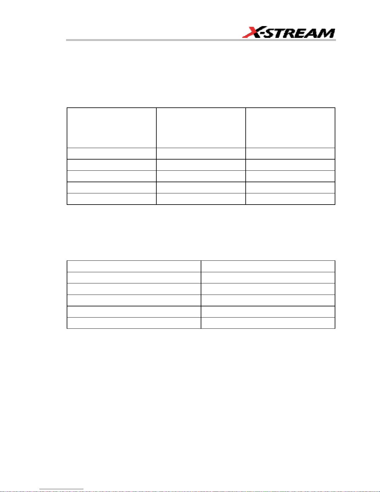
External Timebase Clock: 100 MHz, 50 ohms impedance
External Sample Clock: DC to 1 GHz; 50 ohm BNC input
Roll Mode: Switches automatically at > 0.5 s/div or sampling rate < 20 kS/s
Acquisition System
Single-shot Sample Rate/Ch: 5 GS/s (WaveRunner 6030: 2.5 GS/s)
2 Channel Max. (WaveRunner 6200): 10 GS/s
Maximum Acquisition
Points/Ch
2 Ch/4 Ch
Maximum Acquisition
Points/Ch
(WaveRunner 6051)
1 Ch/2 Ch
Standard 2M/1M 2M/1M
S Memory Option 4M/2M 4M/2M
M Memory Option 8M/4M 8M/4M
L Memory Option 16M/8M 16M/8M
VL Memory Option 24M/12M 24M/12M
Random Interleaved Sampling (RIS): 200 GS/s
Trigger Rate: 125,000 waveforms per second
Acquisition Modes
Single-shot: For transient and repetitive signals: 20 ps/div to 10 s/div
Sequence: 10,000 segments max.:
Memory Option Segments
Standard 500
S Memory Option 500
M Memory Option 1000
L Memory Option 5000
VL Memory Option 10,000
Sequence Time Stamp Resolution: 1 ns
Intersegment Time: 8 µs
WR6K-OM-E Rev A ISSUED: October 2003 19

Operator's Manual
Acquisition Processing
Time Resolution (minimum, single-shot): 200 ps (5 GS/s); 100 ps (10 GS/s)
Averaging: Summed averaging to 1 million sweeps; Continuous averaging to 1 million sweeps
Enhanced Resolution (ERES): from 8.5 to 11 bits vertical resolution
Envelope (Extrema): Envelope, floor, roof for up to 1 million sweeps
Interpolation: Linear, (sinx)/x
Triggering System
Modes: Normal, Auto, Single, and Stop
Sources: Any input channel, External, Ext/10, or line; slope and level are unique to each source
(except line)
Coupling Mode: GND, DC 50 ohms, DC 1 Mohms, AC 1 Mohms
Pre-trigger Delay: 0 to 100% of memory size (adjustable in 1% increments or 100 ns)
Post-trigger Delay: The smaller of 0 to 10,000 divisions, or 86,400 seconds
Holdoff by Time or Events: Up to 20 s or from 1 to 99,999,999 events
Internal Trigger Range: ±5 div from center
Maximum Trigger Frequency: 2 divisions at > 750 MHz with Edge Trigger; 1 division at 750
MHz
750 MHz max. with SMART Trigger @ ≥ 10 mV (subject to
bandwidth limit of scope)
Trigger Level DC Accuracy: ±3% of full scale ±2 mV (typical)
External Trigger Range: EXT/10 ±4 V; EXT ±400 mV
Basic Triggers
Edge/Slope/Line: Triggers when the signal meets the slope and level condition.
SMART Triggers
State or Edge qualified: Triggers on any input source only if a defined state or edge occurred on
another input source. Delay between sources is selectable by time or events.
Dropout: Triggers if the input signal drops out for longer than a selectable time-out between 2 ns
and 20 s.
Pattern: Logic combination (AND, NAND, OR, NOR) of 5 inputs (4 channels and external trigger
input). Each source can be high, low, or don't care. The High and Low level can be selected
independently. Triggers at start or end of pattern.
20 ISSUED: October 2003 WR6K-OM-E Rev A

SMART Triggers with Exclusion Technology
Glitch: Triggers on positive or negative glitches with widths selectable from 600 ps to 20 s or on
intermittent faults.
Signal or Pattern Width: Triggers on positive or negative pulse widths selectable from 600 ps to
20 s or on intermittent faults.
Signal or Pattern Interval: Triggers on intervals selectable from 2 ns to 20 s.
Timeout (State/Edge Qualified): Triggers on any source if a given state (or transition edge) has
occurred on another source
Delay between sources is 10 ns to 20 s, or 1 to 99,999,999
events
Exclusion Triggering: Trigger on intermittent faults by specifying the normal width or period.
Automatic Setup
Autosetup: Automatically sets timebase, trigger, and sensitivity to display a wide range of
repetitive signals.
Vertical Find Scale: Automatically sets the vertical sensitivity and offset for the selected
channels to display a waveform with maximum dynamic range.
Probes
Probes: One PP007 probe per channel standard; optional passive and active probes are
available
Probe System ProBus: Automatically detects and supports a wide variety of compatible probes
Scale Factors: Automatically or manually selected depending on probe used
Color Waveform Display
Type: Color 10.4-inch flat panel TFT LCD with high resolution touch screen
Resolution: SVGA; 800 x 600 pixels
Real Time Clock: Date, hours, minutes, and seconds displayed with waveform; accurate to ±50
ppm; SNTP support to synchronize to precision internet clocks
Number of Traces: Maximum of eight traces; simultaneously displays channel, zoom, memory,
and math traces
Grid Styles: Single, Dual, Quad, Octal, XY, Single+XY, Dual+XY
Waveform Display Styles: Sample dots joined or dots only
WR6K-OM-E Rev A ISSUED: October 2003 21

Operator's Manual
Analog Persistence Display
Analog and Color-graded Persistence: Variable saturation levels; stores each trace's
persistence data in memory
Persistence Selections: Select analog, color, or 3-D
Trace Selection: Activate Analog Persistence on all or any combination of traces
Persistence Aging Time: From 500 ms to infinity
Sweeps Displayed: All accumulated or all accumulated with last trace highlighted
Zoom Expansion Traces
Display up to 4 Math/Zoom traces
Rapid Signal Processing
Processor: Intel 2 GHz (or better) with MS Windows 2000 Platform
Processing Memory: 256 MB with Standard, S, and M memory options; 512 MB with L and VL
options
Internal Waveform Memory
Waveform: M1, M2, M3, M4 (Store full-length waveforms with 16 bits/data point.) Or save to any
number of files (limited only by data storage media).
Setup Storage
Front Panel and Instrument Status: Save to the internal hard drive or to a USB-connected
peripheral device.
Interface
Remote Control: Through Windows Automation or LeCroy remote command set
GPIB Port (optional): Supports IEEE-488.2
Ethernet Port: 10/100Base-T Ethernet interface (RJ-45 connector)
USB Ports: 5 USB ports (one at front of scope) support Windows compatible devices.
External Monitor Port (standard): 15-pin D-Type SVGA compatible DB-15; connect a second
monitor to use dual monitor display mode
Parallel Port: 1 standard
Serial Port: DB-9 COM1 port (not for remote control of scope)
Auxiliary Input
Signal Types: Select External Trigger or Clock input on front panel.
22 ISSUED: October 2003 WR6K-OM-E Rev A

Auxiliary Output
Signal Types: Select from calibrator or control signals output on front panel.
Calibrator Signal: 250 Hz to 1 MHz square wave or DC level; 5 mV to 1.0 V (selectable) into 1
kohms
Control Signals: trigger enabled, trigger out, pass/fail status, square, DC level
Math Tools (standard)
Display up to four math function traces (F1 to F4). The easy-to-use graphical interface simplifies
setup of up to two operations on each function trace. Function traces can be chained together to
perform math-on-math.
absolute value
average (summed)
average (continuous)
derivative
deskew (resample)
difference ()
enhanced resolution (to 11 bits vertical)
envelope
exp (base e)
exp (base 10)
fft (basic)
floor
histogram of 1,000 events
integral
invert (negate)
ln (log base e)
log (base 10)
product (X)
ratio (/)
reciprocal
rescale (with units)
roof
segment
(sinX)/X
square
square root
sum (+)
trend (datalog) of 1,000 events
zoom (identity)
WR6K-OM-E Rev A ISSUED: October 2003 23

Operator's Manual
Measure Tools (standard)
Display any 8 parameters together with statistics, including their average, high, low, and standard
deviations. Histicons provide a fast, dynamic view of parameters and wave shape characteristics.
amplitude
area
base
cycles
delay
delta delay
delta time @ level
duration
duty cycle
fall time (90-10%, 80-20%, @ level)
first
frequency
last
level @ x
maximum
mean
minimum
number of points
overshoot+
overshoot-
peak-to-peak
period
phase
rise time (10-90%, 20-80%, @ level)
rms
std. deviation
time @ level
top
width
x @ minimum (min.)
x @ maximum (max.)
x at max
x at min
Pass/Fail Testing
Test multiple parameters against selectable parameter limits at the same time. Pass or fail
conditions can initiate actions including: document to local or networked files, email the image of
the failure, save waveforms, send a pulse out at the front panel auxiliary BNC output, or (with
GPIB option) send a GPIB SRQ.
Master Analysis Package (XMAP)
This package provides maximum capability and flexibility, and includes all the functionality
present in XMATH, XDEV, and JTA2.
24 ISSUED: October 2003 WR6K-OM-E Rev A

Advanced Math Package (XMATH)
This package provides a comprehensive set of signal WaveShape Analysis tools that provide
insight into the wave shape of complex signals. Additional analysis capability provided by XMAP
includes:
• Intuitive graphical math setup (Processing Web) with unlimited chaining of functions.
• Parameter math -- add, subtract, multiply, or divide two different parameters.
• Histograms expanded with 19 histogram parameters and up to 2 billion events.
• Trend (datalog) of up to 1 million events
• Track graphs of any measurement parameter.
• FFT capability added to include: power averaging, power density, real and imaginary
components, frequency domain parameters, and FFT on up to 25 Mpts.
• Narrow-band power measurements
• Auto-correlation function
• Sparse function
• Cubic and quadratic interpolation function
Advanced Customization Package (XDEV)
This package provides a set of tools to modify the scope and customize it to meet your unique
needs. Additional capability provided by XDEV includes
• Creation of your own measurement parameter or math function, using third-party
software packages, and display of the result in the scope. Supported third-party software
packages include: VBScript, Excel, MATLAB, Mathcad.
• CustomDSO -- create your own user interface in a scope dialog box.
• Add macro keys to run VBScript files.
• Support of plug-ins
Intermediate Math Package (XWAV)
This package is a value-priced version of XMATH, with the following differences:
• Histograms can measure up to 1 million events.
• FFTs of 1 Mpts instead of full acquisition memory capacity
• No Processing Web feature
• No parameter math
WR6K-OM-E Rev A ISSUED: October 2003 25

Operator's Manual
• Does not include the following parameters: Nbpw, Nbphase
• Does not include the following math functions: Phistogram, Ptrace, Correlation, Track,
Sparse, Interpolate
Jitter and Timing Analysis Package (JTA2)
This package provides jitter timing and analysis using JitterTrack (time), Histogram (statistical)
and JitterFFT (frequency) views for common timing parameters, and other useful tools.
• Jitter and Timing parameters with JitterTrack graphs of:
Cycle-to-Cycle
N-Cycle
N-Cycle with Start selection
Frequency
Period
• edge@lv parameter (counts edges)
• Histograms expanded with 19 histogram parameters and up to 2 billion events
• Trend (datalog) of up to one million events
• Persistence Histogram; Persistence Trace
Half Period
Width
Time Interval Error
Setup
Hold
Skew
Duty Cycle
Duty Cycle Error (Delta Width)
Value Analysis Package (XVAP)
This is a value-priced version of LeCroy's premier XMAP package, with the following difference: It
contains XWAV and JTA2, but does not contain XDEV.
26 ISSUED: October 2003 WR6K-OM-E Rev A

Disk Drive Measurement Package (DDM2)
This package provides disk drive parameter measurements and related mathematical functions
for performing disk drive WaveShape Analysis.
• Disk Drive Parameters:
amplitude symmetry
auto correlation s/n
local base
local baseline separation
local maximum
local minimum
local number
local peak-peak
local time between events
local time between peaks
local time between troughs
local time at minimum
local time at maximum
local time peak-trough
local time over threshold
local time trough-peak
local time under threshold
narrow band phase
narrow band power
non-linear transition shift
overwrite
pulse width 50
pulse width 50-
pulse width 50+
resolution
track average amplitude
track average amplitude-
track average amplitude+
• Correlation function
• Trend (datalog) of up to one million events
• Histograms expanded with 19 histogram parameters and up to 2 billion events
General
Auto Calibration: Ensures specified DC and timing accuracy is maintained for 1 year minimum.
Power Requirements: Single phase, 100 to 240 V
100 to 120 V
Voltage Range: 90 to 264 V
(±10%) at 400 Hz (±5%); Automatic AC voltage selection
rms
rms
Frequency Range: 47 to 63 Hz 380 to 420 Hz
Power Consumption: On State: 425 watts (425 VA) max. depending on accessories installed
(internal printer, probes, PC port plug-ins, etc.). Standby State: 12 watts
WR6K-OM-E Rev A ISSUED: October 2003 27
(±10%) at 50/60 Hz (±5%); or single phase,
rms
90 to 132 V
rms

Operator's Manual
Physical Dimensions (HWD): 211 mm x 355 mm x 363 mm (8.3 in. x 13.9 in. x 14.3 in.); height
measurement excludes foot pads
Weight: 10 kg (22 lbs.)
Shipping Weight: 13.6 kg (30 lbs.)
Warranty and Service
3-year warranty; calibration recommended yearly
Optional service programs include extended warranty, upgrades, and calibration services.
Environmental Characteristics
Temperature
Operating: 5 to 40 °C
Storage (non-operating): 20 to +60 °C
Humidity
Operating: 5 to 80% RH (noncondensing) up to 30 °C; upper limit derates linearly to 50% RH
(noncondensing) at 40 °C
Storage (non-operating): 5 to 95% RH (noncondensing) as tested per MIL-PRF-28800F
Altitude
Operating: 3048 m (10,000 ft) max. at ≤ 25 °C
Storage (non-operating): 12,192 m (40,000 ft)
Random Vibration
Operating: 5 Hz to 500 Hz, overall level: 0.31 g
Non-operating: 5 Hz to 500 Hz, overall level: 2.4 g
Shock
Functional Shock: 20 g peak, half sine, 11 ms pulse, 3 shocks (positive and negative) in each of
3 orthogonal axes, 18 shocks total
, 15 minutes in each of 3 orthogonal axes
rms
, 15 minutes in each of 3 orthogonal axes
rms
28 ISSUED: October 2003 WR6K-OM-E Rev A
 Loading...