

Page 1

R
EEMMOOTTEE
R
C
OONNTTRROOLL
C
J
AANNUUAARRYY
J
22000022
M
AANNUUAAL
M
L
Page 2

LeCroy Corporation
700 Chestnut Ridge Road
Chestnut Ridge, NY 10977–6499
Tel: (845) 578 6020, Fax: (845) 578 5985
Internet: www.lecroy.com
© 2002 by LeCroy Corporation. All rights reserved. Information in this publication supersedes all earlier versions.
Specifications subject to change.
LeCroy, ProBus and SMART Trigger are registered trademarks, and ActiveDSO, ScopeExplorer, WaveAnalyzer and
Waverunner are trademarks, of LeCroy Corporation. Centronics is a registered trademark of Data Computer Corp. Epson
is a registered trademark of Epson America Inc. Mathcad is a registered trademark of MATHSOFT Inc. MATLAB is a
registered trademark of The MathWorks, Inc. Microsoft, MS and Microsoft Access are registered trademarks, and Windows
and NT trademarks, of Microsoft Corporation. PowerPC is a registered trademark of IBM Microelectronics. DeskJet,
ThinkJet, QuietJet, LaserJet, PaintJet, HP 7470 and HP 7550 are registered trademarks of Hewlett-Packard Company.
Manufactured under an ISO 9000
Registered Quality Management System
www.lecroy.com to view the
Visit
certificate.
LTXXX-RCM-E Rev B
This electronic product is subject to
disposal and recycling regulations
that vary by country and region.
Many countries prohibit the
disposal of waste electronic
equipment in standard waste
receptacles.
For more information about proper
disposal and recycling of your
LeCroy product, please visit
www.lecroy.com/recycle.
Page 3

T ABLE OF C ONTENTS
INTRODUCTION
PPAARRTTOONNEE::AABBOOUUTTRREEMMOOTTEECCOONNTTRROOL
CHAPTER ONE:
OperateWav erunner byRem ote Control......................................................................................... 5
STANDARDS............................................................................................................................................................6
PROGRAM MESSAGES........................................................................................................................................6
COMMANDS AND QUE RIES............................................................................................................................7
HE ADERS .................................................................................................................................................................8
HE ADER PATHS.....................................................................................................................................................8
DATA...........................................................................................................................................................................9
CHARACTE R DATA ..............................................................................................................................................9
NUMERIC DATA ....................................................................................................................................................9
STRING DATA.......................................................................................................................................................10
BLOCK DATA ........................................................................................................................................................10
RESPONSE MESSAGES .....................................................................................................................................10
USE S
COPEEXPLORER...........................................................................................................................................11
CHAPTER TWO:
Talk, ListenorContr ol....................................................................................................................13
TAL K, LISTE N OR CONTROL ........................................................................................................................13
INTERFACE ............................................................................................................................................................13
ADDRE SS ................................................................................................................................................................14
GPIB SIGNALS......................................................................................................................................................14
I/O BUFFERS.........................................................................................................................................................14
USE IEE E 488.1 STANDARD ME SSAGES ...................................................................................................15
DEVICE CLEAR....................................................................................................................................................15
GROUP EXE CUTE TRIGGER.........................................................................................................................15
REMOTE ENABLE ..............................................................................................................................................15
INTERFACE CL E AR ............................................................................................................................................16
CONFIGURE THE GPIB-DRIVE R SOFTW ARE .......................................................................................16
MAKE SIMPL E TRANSFERS............................................................................................................................17
USE ADDITIONAL DRIVER CALLS.............................................................................................................19
MAKE SERVICE REQUESTS ...........................................................................................................................19
Tak eInstrum ent Po lls ....................................................................................................................21
DO CONTINUOUS POL LING ........................................................................................................................21
TAK E A SERIAL POLL .......................................................................................................................................21
DO A PARAL L EL POLL .....................................................................................................................................22
........................................................................................................1
L ...............3
OVERVIEW
CONT RO L BY GPIB
....................................................................................5
...................................................................13
LTXXX-RCM-E RevB ISSUED: January 2002 iii
Page 4

T ABLE OF C ONTENTS
PERFORM AN *IST POLL .............................................................................................................................. 24
Drive Hard-copy Devi c es o nth eGPIB ..........................................................................................25
READ DATA BY CONTROLLER .................................................................................................................... 25
SEND DATA TO BOTH ..................................................................................................................................... 25
TAL K DIRECTLY TO PRINTE R.....................................................................................................................26
CHAPTER THREE:
Communicat ethroughthe RS-232-C Port .....................................................................................29
HANDSHAKE CONTROL ................................................................................................................................29
EDITING FE ATURES.........................................................................................................................................30
MESSAGE TERMIN ATORS..............................................................................................................................30
SRQ MESSAGE ......................................................................................................................................................31
LONG LINE SPL ITTIN G .................................................................................................................................. 31
REMARKS...............................................................................................................................................................32
SimulateGPIB Messages...............................................................................................................3 3
CH APTER FOUR :
KnowYourWaveform.....................................................................................................................35
LOGICAL DATA BLOCKS ................................................................................................................................ 35
INSPECT WA VEFORM CONTENTS ............................................................................................................. 36
USE THE W A VE FORM QUERY ......................................................................................................................37
INTERPRET VERTICAL DATA ......................................................................................................................39
CALCUL ATE A DATA POINT’S HORIZONTAL POSITION ............................................................... 40
USE THE W A VE FORM COMMAND .............................................................................................................42
Tra nsfer Waveforms at HighSpeed................................................................................................4 3
CH APTER FI VE:
Use Status Register s.......................................................................................................................45
OVE RVIEW ............................................................................................................................................................45
STATUS BYTE REGISTER (STB)....................................................................................................................47
STANDARD EVENT STATUS RE GISTE R (ESR) ...................................................................................... 47
STANDARD EVENT STATUS ENABLE REGISTE R (ESE )................................................................... 48
SERVICE REQUEST ENABL E RE GISTER (SRE )..................................................................................... 48
PARALLEL POLL ENABLE RE GISTE R (PRE) .......................................................................................... 48
INTERNAL STATE CHANGE STATUS REGISTE R (INR).....................................................................48
INTERNAL STATE CHANGE ENABL E REGISTER (INE ) ..................................................................49
COMMAND E RROR STATUS RE GISTE R (CMR)..................................................................................... 49
DEVICE DEPENDEN T ERROR STATUS RE GISTE R (DDR).............................................................. 49
EXECUTION E RROR STATUS REGISTER (EXR)................................................................................... 49
USER REQUEST STATUS REGISTER (URR).............................................................................................49
CONT RO L BY RS232
............................................................. 29
UNDERSTAND AND MANAGE WAVEFORMS
CHECK WAVEFORM STATUS
................................................. 45
................... 35
iv ISSUED: January 2002 L TXXX-RCM-E Rev B
Page 5

T ABLE OF C ONTENTS
PPAARRTTTTWWOO::CCOOMMMMAANNDDS
Use Wa ver unnerCommands andQueries.....................................................................................53
COMMAND NOTATION...................................................................................................................................53
TableofCommands and Queries– By Shor tForm... ................................................................... 55
TableofCommands and Queries– By Subsystem... .................................................................... 59
APPENDI X I
Example 1.....................................................................................................................................2 55
USE THE IN TERACTIVE GPIB PROGRAM “IBIC” ..............................................................................255
Example 2.....................................................................................................................................2 56
USE THE GPIB PROGRAM FOR IBM PC (HIGH-LEVEL FUNCTION CAL LS)..........................256
Example 3.....................................................................................................................................2 60
USE GPIB PROGRAM FOR IBM PC (LOW -LEVELFUNCTION CALLS)........................................260
APPENDIXII
WaveformTemplate......................................................................................................................26 3
IN DE X
.......................................................................................................................275
, GPIB PROGRAM EXAMPLES
, WAVEFORM TEMPLATE
S.......................................... 5 3
.......................................................255
............................................................263
LTXXX-RCM-E RevB ISSUED: January 2002 v
Page 6

BLANK PAGE
vi ISSUED: January 2002 L TXXX-RCM-E Rev B
Page 7

I NTRO DUCTION
Ab out this Manual
This manual explains how to remotely control the oscilloscope, using commands keyed into the external
controller. This controller will normally be a computer, although it could be a simple terminal.
The manual includes a complete list of the commands you’ll need to perform most Wave runner operations
(you can find commands for a few special, optional functions in the software option’s dedicated manual). The
manual has two main parts:
Part One, “A bout R emote C ont r ol,” covers the principles of remote control, and offers practical
examples.
Part Two, “C ommands ,” describes each of the remote control commands and queries for Waverunner
operations. It starts w ith two special indexes that list the commands by short name and by category. Use these
to find the command or query you wish to use.
See also the table of contents and the index at the back of the manual.
As an additional guide, each chapter is prefaced by a summary of its contents.
Wa tch for these icons and the information they signal:
s offer additional hints on how to get the most out of Waverunner actions or features.
TTIIPPs
s bring to your attention important information you should know.
NNOOTTEEs
See also Chapter 12, “U se Waver unner wit h PC,” in the Operator’s M anual.
LTXXX-RCM-E RevB ISSUED: January 2002 1
Page 8

BLANK PAGE
2 ISSUED: January 2002 L TXXX-RCM-E Rev B
Page 9

A
A
P
P
B
B
T
AARRT
O
O
O
O
U
NNE
U
E
T
T
R
Part One of the manual explains how Waverunner operates under remote control. I t covers GPIB and
RS-232-C interfaces, the transfer and formatting of waveforms, and the use of status bytes in reporting
errors.
R
E
E
M
M
O
O
T
T
E
E
C
C
O
O
N
N
T
T
R
R
OLL
O
LTXXX-RCM-E RevB ISSUED: January 2002 3
Page 10

C HAPTER O NE:
In thi s chap te r, see how
To con stru ct pr o gr ammessages
To use comm an ds and queries
To include data, and mak e data strin gs
TouseScopeExplorer for remote control
Over view
4 ISSUED: January 2002 L TXXX-RCM-E Rev B
Page 11
C HAPTER O NE
Over v iew
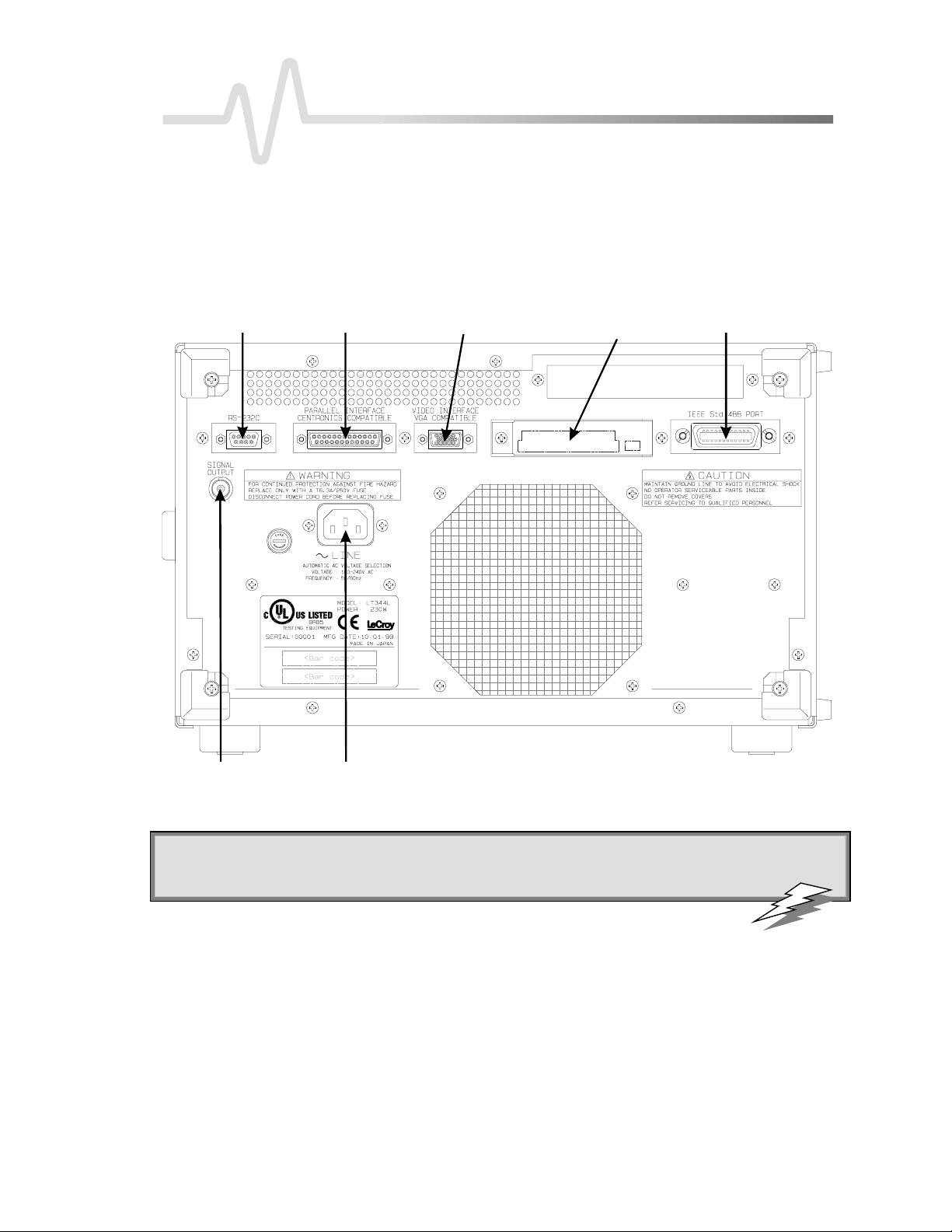
Oper ate W aver unn erbyRemo te Con tr ol
Yo ucan fully control you r Waverunner oscilloscop eremote lyby using either the GPIB (General Purpose
Interface Bus) port or the RS-232-C comm u nic a tion port on the scope rea r pan el, shown belo w. Theonly
actions for which you must use the front panel controls are the powe ring up of the scope and the setting of
remote addresses. Use L eCroy’s ScopeE xplorer software as the ideal interface between scope and PC (see page
11).
RS-232-C Port
Centronics Port
PowerInputBN C Signal Output
External MonitorPort
PC CardSlot
(Memory/ Hard-Disk card )
GPIB Port
Waverunner back panel , including t he G P I B and R S -232-C ports us ed in remot e cont rol .
: Use Waverunner Remote Control Assistant to monitor all your remote control operations. See the
TTIIPP:
COMM_HELP
command in Part Two of this manual, and Chapter 12 of the
Operator ’s Manual
,“Use
Waverunner with PC”.
LT3XX-RCM-E RevB ISSUED: January 2002 5
Page 12

P ART O NE: ABOUT REMOTE CONTROL
STANDARDS
*
LeCroy remote control commands conform to the GPIB IE E E 488.2
ex ten sionof the IEEE 488.1 standa rd, whic h dea ls mainly with ele ctrical andmech a n ical issue s. The IEEE
488.2 recommendations ha v ealso be e nadopted for RS-232-C comm un ications wh erever appropriate .
PROGRAM MESSAGES
Yo ucontrol the oscilloscop eremotelyusingprogrammessa g es that consist of one or sev eral commands or
qu e rie s . The program messa g e s yousend from the ex ternal controller to the W a v erunne r oscilloscop emu st
conform to precise format structures. The oscilloscope will execute all program messages sent in the correct
form, but will igno re those with errors.
You can use upper- or lowe r-case characters, or both, in program messages.
W a rningor error messag es are normally not reported unle ss the controller ex p licitlyexa m ine sthe rele v a n t status
register, or if the status-enable registers have been set so that the controller can be interrupted w hen an error
occurs. If you connect an external monitor to the W averunner’s RS-232-C port, how ever, yo uw ill be able to
observe all your remote control transactions, including error messages, as they happen. See the command
COMM_HELP in Part Two, “Commands.”
Program messages are separated by semicolons ; and end in a terminator:
<command/query>;.........;<command/query> <terminator>.
The oscilloscop ew ill not decod ean incomingprogram messag ebefore rece i vingits terminator. The exception is
w h e nthe program mes sa g eis longe r thanthe 256 by te input buffer; thenthe oscilloscop ew ill start ana ly zingthe
message whe n the buffer is full. Commands and queries are executed in the order in w hich they are transmitted.
standard. This may be considered an
In GPIB mode, the follow ingare valid terminators:
<NL > New-line character (i.e. the ASCII new-line character, w hose decimal value is 10).
<NL >< EOI> New-line character with a simultaneous < EOI> signal.
<EOI> < E OI> Signal together w ith the last character of the program message.
The <NL > <EOI> terminator is always use d in resp on semes sa g e s sent by the oscilloscope to the controller.
In RS-232-C commu n ic a tions , you can de fine the terminator with the comman dCOMM_RS232. The default
value is <CR>, which is the ASCII carriage return charac ter, who sede cimal valu eis 13.
NNOOTTEE:
: T he < E OI> signal is a dedicated GPI B interface line, which can
be set witha special call to the GPIB inter face driv er. Referto theGPIB
in ter f ace manufacturer’s manual and supp o r t pr o gr am s .
*ANSI/IEE E Std. 488.2–1987, IE EE Standard Codes, Formats, Protocols, and Common Commands. The Institute of Electrical and Electronics E nginee rs
Inc., 345 E ast 47th Street, New York, NY 10017 USA.
6 ISSUED: January 2002 LTXXX-RCM-E RevB
Page 13

C HAPTER O NE:
COMMAND S AND QUERIES
Program messages are made up of one or more commands or queries. While the command directs the
oscillosco p eto chang eits state (for ex a m p le, its timeba seor vertical sensitivity) the query ask s the oscillosc op e
about that state. Very often, you will use the same mnemonic for a command and a query , the query being
identified by a ? after the last character.
For ex a m p le, to chang ethe timeba seto 2 ms/div , send this comma n d to the oscilloscop e:
TIME_DIV 2 M
Or, to ask the oscilloscop eabo u t its timeb a se, send this query:
TIME_DIV?
A query causes the oscilloscop eto sen d a respon semess a g e. The control programshouldread this messa g ew ith
a ‘read’ instruction to the GPIB or RS-232-C interface of the controller.
Theresponsemessagetotheabovequerymightbe:
TIME_DIV 10 NS
The portion of the query preceding the question mark is repeated as part of the response message. If desired,
this text can besuppressed withthecommand COMM_HEADER.
Depending on the state of the oscilloscope and the computation to be done, several seconds may pass before a
response is received. Command interpretation does not have priority over other oscilloscope activities.
The general form of a command or a query consists of a command header, < header> , optionally followed by
one or several parameters, < data> , separated by commas:
Overview
<header>[?] < data>,...,< data>
The notation [?] shows that the question mark is optional (turning the command into a query).
There is a space between the header and the first parameter.
There are commas between parameters.
The following are examples of how program
messages are made up of commands and queries...
GRID DUAL: This program message consists of a
sing lecomma n d that instructs the oscilloscope to
display a dual grid.
The terminator is not show n , as it is usu ally automaticallyadd ed by the interfacedriver routine writing to GPIB
or RS232.
DZOM ON; DISPLAY OFF; DATE?:This program message consists of tw o commands, followed by a
query . They instruct the oscilloscope to turn on the multi-zoom mode, turn off the display , and then ask for the
current date. Again, the terminator is not shown.
DATE 15,JAN,1993,13,21,16: This command instructs the oscilloscope to set its date and time to 15
JAN 1993, 13:21:16. The comma n dhea d e r DATE indicates the action, the 6 data values specify it in detail.
LT3XX-RCM-E RevB ISSUED: January 2002 7
: Set the controller I/ O timeout conditions
TTIIPP:
to thr e eormore seconds to giv ethescop etime
to respo n d. An incorr ect query will not get a
re sp o nse; and, if Remo te Con trol Assistant is
ena bled, a beep will sound.
Page 14

P ART O NE: ABOUT REMOTE CONTROL
HEADERS
The hea d e r is the mnemon ic form of the operation to be pe rformed by the oscilloscope. Most comma ndand
query headers have a long form, which allows them to be read more easily, and a short form for better transfer
and decoding spee d. The two are fully equivalent and you can use them interchangeably. For example,
TRIG_MODE AUTO and TRMD AUTO are two separate but equivalent commands for switching to the
automatic trigger mode.
Some comman dor qu e ry mnemo nic s are impose dby the IEEE 488.2 standard. Theyare stand a rdize dso that
differen t oscilloscop es w ill presen t the same programminginterfacefor similar functions.All thesemnemo n ics
beginwithanasterisk* . For example, the command *RST is the IEEE 488.2 impose dmnem on ic for rese tting
the oscilloscope, whe reas *TST? instructs the oscilloscop eto perform an internal self-test andreport the
outcome.
HEADERPATHS
Certain commands or queries apply to a sub-section of the oscilloscope; for example, a single input channel or a
trace on the display . In such cases, you must prefix the heade r by a path name that indicates the channel or trace
to which the command applies. The header path normally consists of a two-letter path name followed by a
colon : immediately preceding the command heade r. One of the wave form traces can usually be specified in the
header path:
HEADER PAT H N AM E WAV E FOR M T RACE
C1, C2
C3, C4
M1, M2, M3, M4
TA, TB, TC, TD
EX, EX10, EX5
LINE
Example: C1:OFST -300 MV Command to set the offset of Channel 1 to −300 mV.
You need only specify a header path once. Subsequent commands with header destinations not indicated are
assumed to refer to the last defined path. For example, the queries C2:VDIV?; C2:OFST? ask: What is the
vertical sensitivity and the offset of channel 2? While the queries C2:VDIV?; OFST? ask exactly the same
qu e stion without repe a tingthe path.
Channels 1 and 2
Channels 3 and 4 (on four-channel models)
Memories 1, 2, and3 an d4
Trac es A, B, C an dD
External trigger
LINE sourcefor trigger
8 ISSUED: January 2002 LTXXX-RCM-E RevB
Page 15

C HAPTER O NE:
DATA
Whenever a command or query uses additional data values, the values are expressed as ASCII characters. There
is a single exception: the transfer of wave forms with the command/query WAVEFORM, where the wa veform can
be expressed as a sequence of binary data values. See Chapter 4, “Wavef or m St r uct ur e.” ASCII data can
have the form of character, numeric, string, or block data.
CHARACTER DATA
Thesearesimplewordsor abbreviationsto indicate a specific action.
Example: DUAL_ZOOM ON
In this example, the data value ON commands the dual zoom mode to be turned on (the data value OFF will
havetheoppositeeffect).
How eve r, this can become more complex. In some commands, where you can specify as many as a dozen
different parameters, or wherenot all theparametersareapplica ble at thesametim e, theformat re quires pairs of
data values . The first value names the parameter to be modified, while the second gives its value. Only those
parameter pairs changed need to be indicated.
Example: HARDCOPY_SETUP DEV,EPSON,PORT,GPIB
In this example, two pairs of parameters have been used. The first specifies the device as an EPSON (or
compatible) printer, w hile the second indicates the GPIB port. While the command HARDCOPY_SETUP allow s
many more parameters, either they are not relevant for printers or they are left unchanged.
Overview
NUMERIC DATA
The numeric data type is used to enter quantitative information. Numbers can be entered as integers or
fractions,or in exponential representation:
TA:VPOS -5 Move the displaye d trace of Trace A downw ards by five divisions.
C2:OFST 3.56 Set the DC offset of Channel 2 to 3.56 V.
TDIV 5.0E-6 Adjust thetimebaseto5µsec/div.
Example: There are many way s of setting the timebase of the oscilloscope to 5 µsec/div:
TDIV 5E-6 Exponential notation, without any suffix.
TDIV 5 US SuffixmultiplierU for 1E −6, with the(optional) suffixS for seconds.
or
TDIV 5000 NS
TDIV 5000E-3 US
Yo ucan follow nume ric value s with multiplie rs and units, to modify the valu eof the nu merical ex p re ssio n.The
following mnemonics are recognized:
LT3XX-RCM-E RevB ISSUED: January 2002 9
Page 16

P ART O NE: ABOUT REMOTE CONTROL
MULTIPLIER E XP .NOT E. SUFFIX MULTIPLIER E XP.NOTE . SUFFIX
EX 1E18 Exa- PE 1E15 PetaT 1E12 Tera- G 1E9 GigaMA 1E6 Mega- K 1E3 k iloM
N
F
STRIN G DATA
Thisdata type enables youto transfera (long) stringof characters asasingleparameter. Simplyenclose any
sequence of ASCII characters betwee n single or double quotation marks:
MESSAGE ‘Connect probe to point J3’
The oscilloscope displays this message in the Message field above the grid.
BLOCK DATA
These are binary data values coded in hexade cimal ASCII: four-bit nibbles translated into the digits 0 through 9
or A through F, and transmitted as ASCII characters. They are used only for the transfer of wa veforms from
Wa verunner to controller (WAVEFORM) and for Wa verunner panel setups (PANEL_SETUP)
RESPONSE MESSAGES
The oscilloscope sends a response message to the controller in answ er to a query . The format of such messages
is the same as that of program messages: individual responses in the format of commands, separated by
semicolon s ; and ending in terminators. These messages can be sent back to the oscilloscope in the form in
which they were received, to be accepted as valid commands. In GPIB response messages, the < NL > < E OI>
terminator is alwa ys used.
1E−3
1E−9
1E−15
milli- U
nano- PI
femto- A
1E−6
1E−12
1E−18
micropicoatto-
Example: The controller sends the program message:
TIME_DIV?;TRIG_MODE NORM;C1:COUPLING? (terminator not shown).
The oscilloscope might respond to this with:
TIME_DIV 50 NS;C1:COUPLING D50 (terminator not shown) .
The response message refers only to the queries: TRIG_MODE is left out. If this responseis sent backto the
oscillosco p e, it is a valid program messa g efor setting its timebase to 50 ns/div and the inp u t couplin gof
Channel 1 to 50 Ω.
Whenever you expect a response from the oscilloscope, you must have the control program instruct the GPIB
or RS-232-C interface to rea dfrom the oscilloscop e. If the controller sends another program message without
reading the response to the previous one, the response message in the output buffer of the oscilloscope will be
10 ISSUED: January2002 LTXXX-RCM-E Rev B
Page 17

C HAPTER O NE:
disca rde d . The oscilloscope kee ps to stricter rules for resp on seme ssa g e sthan for acc e p tan ceof program
messages. While you can send program messages from the controller in upper- or lower-case characters,
response messages are always returned in upper-case. Program messages may contain extraneous spaces or tabs
(white space), but response messages will not. And while program messages may contain a mixture of short and
long command or query heade rs, response messages alwa ys use short headers by default.
How eve r, you can use the command COMM_HEADER to force the oscilloscopeto uselong hea ders, or noneat
all. If the response header is omitted, the response transfer time will be minimized. But the response will not be
ableto be sent back to the oscilloscope. Suffix units are also supp resse d in the response .
If you were to set the trigger slope of Channel 1 to negative, the query C1:TRSL? mig ht yie ld the following
response s:
Overview
C1:TRIG_SLOPE NEG hea der format: long
C1:TRSL NEG hea der format: short
NEG
header format: off
: Wav efo r m s you obtain fromthe
TTIIPP:
oscilloscope using the query
WAVEFORM?
a special kind of response message. Control
theirex act for m at by using the
COMM_FORMAT
an d
COMM_ORDER
are
commands.
USE SCOPEEXPLORER
ScopeExplorer is an easy-to-use and practical software tool for interfacing your W ave runner oscilloscope with a
PC running Windows:
1. Connect the scope to a PC using either the GPIB (you’ll need a PC with GPIB card installed) or PCstandard RS-232-C port on the scope ’s rea r pan el.
2. DownloadScopeExplo rer free of ch argeat http:/ / www.lecroy .com/ scopeexplorer. Or inquire at your
LeCroy customer service center.
3. Having installed ScopeExplorer, open it as you would any Windows program. Use its on-line help to do the
follow in g :
Use the teletype-like terminal to send standard remote control commands from computer to
oscillosco p e, an dto displa ythe W a v erunne r respon seon the PC.
Control the scope by means of an interactive, virtual scope front panel.
Pipe sequences of commands from a file to the scope, then send the scope’s responses to another file.
Transfer pixel-for-pixel copies of your Wa verunner display to PC, then view them, print them, or both
from the computer. With a single press of a button or key , you can copy bitmap wave form images to
the Windows Clipboard, ready to paste into any Windows application.
Capture Wa verunner front panel setups and, using a long filename, store them on the computer. You
can then transfer them back into the scope to reproduce an identical setup.
Transfer your waveforms to PC, and store them in either the compact L eCroy Binary format, or an
ASCII version compatible with PC-based analysis products.
LT3XX-RCM-E RevB ISSUED: January 2002 11
Page 18

C HAPTER T WO:
In thi s chap te r, see how
To address yo urWav er un n erscope forGPIB
Toconfi gureGPIB softwa re
To enable remote or local control
To mak e transfer s of data
To makeservice reque sts
To poll Waverunner
To driv e har dcopy devices
ControlbyGPIB
12 ISSUED: January2002 LTXXX-RCM-E Rev B
Page 19

C HAPTER T WO
ControlbyGPIB
Talk, L isten, or Control
Yo ucan remotelycontrol you r W a v e runn e r oscilloscope, usingthe Gene ra l PurposeInterfaceBus (GPIB).
GPIB is similar to a standard computer bus. But while the computer interconnects circuit cards by means of a
bac k plane bus, the GPIB interconn e cts inde p endent devices (os cillos copes and compute rs, for ex a m p le) by
means of a cable bus. GPIB also carries both program and interface messages.
Progr ammessages, often called device dependent messages, contain programming instructions, measurement
results,and oscilloscopestatus and wa v eform data.
Interface messages manage the bus itself. They perform functions such as initialization, addressing and
“unaddressing” of devices, and the setting of remote and local modes.
TALK, LIST EN, OR CONTROL
On the one hand, devices connected by GPIB to your Wa verunner oscilloscope can be listeners, talkers, or
controllers. A talker sends program messages to one or more listeners, w hile a controller manages the flow of
information on the bus by sending interface messages to the devices. The host computer must be able to play
all three roles. For details of how the controller configures the GPIB for specific functions, refer to the GPIB
interface manufacturer’s manual.
On the other hand, the Waverunner can be a talker or listener, but
IN T ERFACE
W averunne r interface cap abilities includethe following IEEE 488.1 de finitions:
AH1 Complete Acceptor Handshake DC1 CompleteDeviceClearFunction
SH1 Complete Source Handshake DT1 Comp lete DeviceTrigger
L4 Partial Listener Function PP1 Parallel Polling : remo te configurable
T5 Comp le te Talke r Function C0 No Controller Functions
SR1 Comp le te Service Reque s t Function E2 Tri-stateDrive rs
RL1 Complete R emote/Local Function
LTXXX-RCM-E RevB ISSUED: January 2002 13
NOT a controller.
Page 20

P ART O NE: ABOUT REMOTE CONTROL
ADDRE SS
Every device on the GPIB has an address. To address Wa verunner, set the remote control port to GPIB by
means of thescope ’s front pane l UTILITIES button and on-scree nmen u s .If yo usele ct “RS-232” in the same
way, the oscilloscop ew ill execute over the GPIB solely“talk-only ” operations,such as driving a printer. Setting
W averunne r to “RS-232” enab le sthe oscilloscop eto becontrolled throughtheRS-232-C port. See Chapter 12
of the Operator’s M anual for how to do this.
If youaddre ss Wa v e runn e r to talk, it will rema in in that state until it receives a uni versal untalk comma n d
(UNT), its ow n listen address (ML A), or ano ther oscillosco p e’s talk addres s .
If youaddre ss Wa v e runn er to listen, it w ill rema inconfiguredto listen until a univ e rsa l unlisten comma n d
(UNL ), or its own talker address (MTA), is received.
GPIB SIGNAL S
The GPIB bus systemconsists of 16 signal lines and eigh t ground or shieldlines .The signa l lines are divided
into three groups:
Data Lines:Theseeig h t lines , usua llycalle d DI01 throughDI08, carry both prog ramand interface messag es.
Most of the messages use the 7-bit ASCII code, in which case DI08 is unused.
Handshake Lines:These three lines control the transfer of message bytes between devices. The process is
called a three-wire interlocked handshake, and it guarantees that the message bytes on the data lines are sent
and received without transmission error.
Inter face Management Lines: These five lines manage the flow of information across the interface:
ATN (ATteNtion): The controller drives the ATN line true when it uses the data lines to send interface
mes sa g es suchas talk and listen addresses or a deviceclea r (DCL ) messa g e. WhenATN is false, the bus is in
data mode for the transfer of program messages from talkers to listeners.
IFC (InterFaceClear):The controller sets the IFC line true to initialize the bus.
RE N (RemoteENable): The controller uses this line to place devices in remote or local program mode.
SRQ (ServiceReQues t ): AnydevicecandrivetheSRQlinetruetoasynchronouslyrequest servicefromthe
controller. This is the equivalent of a single interrupt line on a computer bus.
EOI(End Or Identify):This line has tw o purposes: The talker uses it to mark the end of a message string.
The controller uses it to tell devices to identify their response in a parallel poll (discussed later in this section).
I/O BUFFE RS
The oscilloscope has 256-byte input and output buffers. An incoming program message is not decoded before
a message terminator has been received. However, if the input buffer becomes full (because the program
mes sa g eis longe r than the buffer),the oscilloscop estarts analy z ingthe messa ge. In this casedata trans miss ion
is temp o rarilyhalted , and the controller maygen e ratea timeo u t if the limit was set too low.
14 ISSUED: January2002 LTXXX-RCM-E Rev B
Page 21

C HAPTER T WO:
USE IE E E 488.1 STAN DARD M E SSAGE S
The IEEE 488.1 stand a rd specifies not onlythe mech a n ical andele ctrical asp ects of the GPIB, but also the
low-level transfer protocol. For instance, it defines how a controller addresses devices, turns them into talkers
or listeners, resets them or puts them in the remote state. Such interface messages are executed with the
interface management lines of the GPIB, usually with ATN true.
ControlbyGPIB
All these messages except GET are executed
immediately upon receipt.
The command list in Part Two of this manual does
not contain a command for clearing the input or
output buffers, nor for setting the oscilloscope to the
remote state.
This is because such commands are already specified as IEEE 488.1 standard messages. Refer to the GPIB
interface man u al of the host controller as w e ll as to its supp ort progra ms , whic h should contain spec ia l calls for
theexecutionof thesemessages.
The following description covers those IEEE 488.1 standard messages that go beyond mere reconfiguration of
the bus and that have an effect on Wave runner operation.
DEVICE CLEAR
In response to a universal Device CLear (DCL ) or a Selected Device Clear message (SDC), Wave runner clears
the input or output buffers, cancels the interpretation of the current command (if any) and clears pending
commands. However, statusregisters and status-enableregisters arenot cleared. Although DCL will have an
immediate effect, it can take several seconds to exe cute if the oscilloscopeis busy.
GROUP EXECUTE TRI GGER
The Group E xecute Trigger message (GET) causes Waverunner to arm the trigger system, and is functionally
ide ntica l to the *TRG command.
N OT E : In addition to the IE E E 488.1 interface
message standards, the IE E E 488.2 standard
specif ies certainstandar dized pr ogrammessages,
i.e., comm and h eader s. Theyare iden tified witha
leadin g asterisk * and are listed in the System
Commands section.
RE MOT E ENABL E
This interface message is executed when the controller holds the Remote ENable control line (RE N) true,
allowing you to configure the oscilloscope as a listener. All the front panel controls except the menu buttons
are disabled. The menu indications on the right-hand side of the screen no longer appea r, since menus cannot
now be operated manually . Instead, the text REMOTE E N ABL E appears at the top of the menu field to
indica te that the oscilloscop eis set in the remote mode . When e v er the controller returns the RE N line to false,
all oscillosco pes on the bus return to GO TO LOCAL.
When you press the GO TO LOCAL menu button, the scope returns to front panel control, unless you have
pla ced the oscillosco p ein Local LOckout (LLO) mode (seebelo w).
LTXXX-RCM-E RevB ISSUED: January 2002 15
Page 22

P ART O NE: ABOUT REMOTE CONTROL
The Go To Local message (GTL) causes the oscilloscopeto return to local mode . All front pa n e l controls
become active and the normal menus reappe ar. Thereafter, whene ver the oscilloscope is addressed as a listener
it will be immediately reset to the remote state, except when the LL O command has been sent.
When you activate Local Lockout the scope can only be returned to its local state by returning the L LO to
false.Whene v er youreturn the oscillosco p eto the remote state the local lockou t modewill immedia te ly
becom eeffective again.
The L ocal LOckout message (L L O) causes the GO TO LOCAL menu to disappear. You can send this message
in local or remote mode. But it only becomes effective once you have set the oscilloscope in remote mode.
INTERFACE CLEAR
The InterFace Clear message (IFC) initializes the GPIB but has no effect on the operation of the Wa verunner.
NNOOTTEE:
: To illu strate theGPIB progr amming concep ts a nu mberof examples writteninBASICA are
included here. It is assumed that the controller is IBM- PC compatible, running under DO S, and that
it is equipp ed with a N ational Instrumen ts GPIB interface card. Neverth eless, GPIB pro gram m in g
withotherlanguages such as C orPascal is quite similar . If yo u’re using ano th ertype of comp uteror
GPIB interface, refe rto the interface manual forinstallatio npr o ced ur es and subro utine calls.
CONF IGURE TH E GPIB DRIVER SOFTWARE
1. Verify that the GPIB interface is properly installe d in the computer . If it is not, followthe interface
man u facture r’s installation instructions. In the caseof the National Instruments interface , it is pos sibleto
modify the base I/ O address of the board, the DMA channel number, and the interrupt line setting using
switches and jumpers. In the program examples below, default positions are assumed.
2. Connect Wave runner to the computer with a GPIB interface cable.
3. Set the GPIB address to the required value. The program examples assume a setting of 4.
The host computer requires an interface driver that handles the transactions betwe en the operator’s programs
and the interface board.
In the caseof the National Instrume n ts interface , the installation proced u re will:
a. CopytheGPIB handler GPIB.COM into theboot director y.
b. Modify the DOS system configuration file CONFIG.SYS to declare the presence of the GPIB handler.
c. Crea te a sub-directory calle dGPIB-PC, and install in GPIB-PC a numb e r of files and programs useful for
testing and reconfiguring the system, and for writing user programs.
The following files in the sub-directory GPIB-PC are particularly useful:
IBIC.EXE allows interactive control of the GPIB by means of functions entered at the keyboard. Use of this
program is highly recommended to anyoneunfamiliar with GPIB programming or w ith Wave runner’s remote
commands.
16 ISSUED: January2002 LTXXX-RCM-E Rev B
Page 23

C HAPTER T WO:
DE CL.BAS is a declaration file that contains code to be included at the beginning of any BASICA application
program.Simpleapplicationprograms can bequicklywritten byappendingtheoperator’s instructionsto
DECL.BAS andexecuting thecompletefile.
IBCONF.EXE is an interactive program that allows inspection or modification of the current settings of the
GPIB handler. To run IBCONF.EXE, refer to the National Instruments manual.
ControlbyGPIB
NNOOTTEE:
: I n the program examples in this section, it is assumed that the N ational Instruments GPIB
driv erGPIB.COM is in its default state, i.e., that the user has no t modified it with IBCONF.E XE .
T his means that the interface board can be referred to by the symbolic name ‘GPIB 0’ and that devices
onthe GPIB bus withaddresses between1and 1 6can be called by the sym bol ic names ‘DEV1 ’ to
‘DEV1 6 ’. If you h av ea NationalInstruments PC2 in ter f ace card r ath erth anPC2A, yo u must run
IBCONF to declare th epresen ceof thi s card ratherthanthe defau l t PC2A.
MAKE SIMPLE TRANSFERS
For a large number of remote control operations it is sufficient to use just three different subroutines
(IBFIND, IBRD and IBWRT) provide d by National Instrume n ts. The following complete program rea d s the
timebase setting of Waverunner and displays it on the terminal:
1–99
100 DEV$=“DEV4”
110
120 CMD$=“TDIV?”
130 CALL IBWRT(SCOPE%,CMD$)
140
150 PRINT RD$
160
<DECL.BAS>
CALL IBFIND(DEV$,SCOPE%)
CALL IBRD(SCOPE%,RD$)
END
Lines 1–99 are a copy of the file DECL .BAS supplied by N ational Instruments. The first six lines are required
for the initialization of the GPIB handler. The other lines are declarations w hich may be useful for larger
programs, but are not really required code. The sample program above only uses the strings CMD$ and RD$,
which are declared in DE CL .BAS as arrays of 255 characters.
Lines 100 and 110 openthe deviceDEV4 and associatewith it thedescriptor SCOPE%. All I/O calls after that
w ill refer to SCOPE%. The default configuration of the GPIB handler recognizes DEV4 andassocia tes with it a
device with the GPIB address 4.
Lines 120 and 130 prepare the command string TDIV? and transfer it to the oscilloscope. The command
instructs the oscilloscope to respond with the current setting of the timebase.
LTXXX-RCM-E RevB ISSUED: January 2002 17
Page 24

P ART O NE: ABOUT REMOTE CONTROL
Lines 140 and 150 read the response of the oscilloscope and place it into the character string RD$.
Line 170 displays the response on the terminal.
NOTE: DECL.BAS requ ires acce ss to the file BIB.M du ring the GPIB initializa tion. BIB.M
is one of the files supplied by N ational Instruments, and it must exist in the directory
currently in use.
Thefirst two linesof DE CL.BAS both contain astring XXXXX, whichmustbe replaced bythenumber of
bytes that determinethemaximum workspace for BASICA (computed bysubtracting thesizeof BIB.M from
the spa cecurrently availa b lein BASICA). For ex a m p le, if the size of BIB.M is 1200 bytes , and whe nBASICA
is loaded it repo rts “60200 bytes free,” you should rep la ce“XXXXX” bythe value 59 000 orless.
When running this sample program, Wa verunner w ill automatically be set to the remote state w hen IBWRT is
exe cuted, and will remain in that state. Pressing the LOCAL menu button will return Wa verunner to local mode
if the GPIB handler was modified to inhibit L ocal LOckout (LL O). Here is a slightly modified version of the
sample program that checks if any error occurred during GPIB operation:
1–99 <DECL.BAS>
100 DEV$=“DEV4”
110 CALL IBFIND(DEV$,SCOPE%)
120 CMD$=“TDIV?”
130 CALL IBWRT(SCOPE%,CMD$)
140 IF ISTA% < 0 THEN GOTO 200
150 CALL IBRD(SCOPE%,RD$)
160 IF ISTA% < 0 THEN GOTO 250
170 PRINT RD$
180 IBLOC(SCOPE%)
190 END
200 PRINT “WRITE ERROR =”;IBERR%
210 END
250 PRINT “READ ERROR =”;IBERR%
260 END
TheGPIB statuswordISTA%, the GPIB error variable IBERR% and the count variable IBCNT% are defined
by the GPIB handler and are updated with every GPIB function call. Refer to the National Instruments manual
for details. The sample program above w ould report if the GPIB address of the oscilloscope was set to a value
other then 4. L ine 180 resets the oscilloscope to local with a call to the GPIB routine IBLOC.
18 ISSUED: January2002 LTXXX-RCM-E Rev B
Page 25

C HAPTER T WO:
USE ADDIT I ONAL DRIVER CALLS
IBLOC is used to execute the IE EE 488.1 standard message Go To L ocal (GTL), i.e. it returns the
oscillosc op eto the loca l state. The programmin gexample aboveillustrates its use.
IBCLR executes the IE EE 488.1 standa rd messa g eSelectedDeviceClear (SDC).
IBRDF and IBWRTF, respe ctively , allowdata to be read from GPIB to a file, and w ritten from a file to
GPIB. Transferring data directly to or from a storage device does not limit the size of the data block, but
may be slow e r than transferring to the computer memory .
IBRDI andIBWRTI allowdatatobereadfromGPIBtoanintegerarray,andwrittenfromintegerarray
to GPIB. Since the integer arrayallows storageof up to 64 kiloby tes (in BASIC), IBRDI and IBWRTI
should be used for the transfer of large data blocks to the computer memory , rather than IBRD or
IBWRT, w h ichare limited to 256 by tes by the BASIC string length. Note that IBRDI andIBWRTI only
exist for BASIC, since for more modern programming languag es, such as C, the functions called IBRD
andIBWRT are far less limited in da ta blocksize .
IBTM O can be used to change the timeout value during program execution. The default value of the
GPIB driver is 10 seconds — for example, if the oscilloscop edoe s not respo n d to an IBRD call, IBRD
will return with an error after the specified time.
IBTRG executes the IEEE 488.1 stand a rd messa g eGroup Exe cu te Trigge r (GE T), wh ichcaus e s
Waverunner toarm the trigger system.
National Instruments supply a number of additional function calls. In particular, it is possible to use the socalle dboard leve l calls , wh ichallowa very detaile dcontrol of the GPIB.
ControlbyGPIB
NOTE: Th eSRQ bit is latch e dunti lthe con troll e rread s the STatus Byte Register(STB). Th eaction
of reading the ST B with the command
*STB?
clears the r egiste rcon te nts ex cept th eMAV bit (bit 4)
until a n eweven t occurs. Service requesting can be disabled by clearin g the SRE register
w i ththe
MAKE SERVICE REQUESTS
When a W ave runner is used in a remote application, events often occur asynchronously, i.e., at times that are
unpredictab lefor the host computer.The most common ex a m p leof this is a trigge r w a it after the oscilloscop e
is armed: the controller must wait until the acquisition is finished before it can read the acquired wa veform.
The simplest way of checking if a certain event has occurred is by either continuously or periodically reading
the status bit associa te d with it until the required transition is detected. Continuous status bit pollingis
described in more detail below. For a complete explanation of status bits refer to Chapter 5.
Perhaps a more efficient wa y of detecting events occurring in the oscilloscope is the use of the Service Reque st
(SRQ). This GPIB interrupt line can be use dto interrupt program ex ecution in the controller. The controller
can thenex e c u te other program s w h ilew a iting for the oscilloscope. Unfortuna te ly, not all interface
manufacturers support theprogrammingof interrupt service routines. In par ticular, NationalInstruments
supports only the SRQ bit within the ISTA% status word. This requires you to continuously or periodically
LTXXX-RCM-E RevB ISSUED: January 2002 19
*SRE 0 command.
Page 26

P ART O NE: ABOUT REMOTE CONTROL
check this word, either explicitly or with the function call IBWAIT. In the absence of real interrupt service
routines the use of SRQ may not be very advantageous.
In the default state, after pow er-on, the Service ReQuest is disabled. You enable SRQ by setting the Service
Request E nable register with the command “*SRE ” and by specifying which event should generate an SRQ.
Wa verunner will interrupt the controller as soon as the selected event(s) occur by asserting the SRQ interface
line. If several devices are connected to the GPIB, you may be required to identify which oscilloscope cause d
the interrupt by serial pollingthe various device s .
Example:To assert SRQ in response to the events “new signal acquired” or “return-to-local” (pressing the
soft key/ menu button for GO TO L OCAL).T hese events are tracked by the INR register, which is ref lected in
the SRE register as the INB summary bit in position 0. Since bit position 0 has the value 1, the command
*SRE 1 enables the generation of SRQ whe never the IN B summary bit is set.
In addition, the events of the INR register that may be summarized in the INB bit must be specified. The
event “new signal acquired” corresponds to INE bit 0 (value 1) while the event “return-to-local” is assigned to
INE bit 2 (value 4). The total sum is 1 + 4 = 5. Thus the command INE 5 is needed:
CMD$=“INE 5;*SRE 1”
CALL IBWRT(SCOPE%,CMD$)
Example:To assert SRQ whe n soft key4 (fourth menu button from top of screen) is pressed. The event “soft
key4 pressed” is tracked by the URR register. Since the URR register is not directly reflected in STB but only in
the ESR register (URR, bit position 6), the E SE enable register must be set first with the command *ESE 64
to allow the URQ setting to be reported in STB. An SRQ request will now be generated provided that the ESB
summary bit (bit position 5) in the SRE enable register is set (*SRE 32):
CMD$=“*ESE 64;*SRE 32”
CALL IBWRT(SCOPE%,CMD$)
NNOOTTEE:
: The term “soft-key,” used her e in refer en ce to r em ote oper ation s, is syno n y m o us with “men u
button ,” used in the accom p anyin g Oper ato r’s Manual to meanfront panel operation s. Both term s
refer to the column of seven buttons running parallel to the screen on the Waverunner front panel and
th emenu fun ctions th e ycontro l .
20 ISSUED: January 2002 L TXXX-RCM-E Rev B
Page 27

C HAPTER T WO:
ControlbyGPIB
Take Instrumen t Polls
Youcan regularlymonitor state transitions withintheoscilloscopebypolling selected internal status registers.
Thereare four ba sic pollingmethods you can useto detec t the occurrence of a giv e nevent: continuou s , serial,
pa rallel, an d *IST. By far the simplest of these is continuous polling. The others are appropriate only when
interrupt-service routines (servicing the SRQ line) are supported, or multiple devices on GPIB require constant
monitoring. To emphasize the differences betwe en the methods, described below, the same example
(determining whether a new acquisition has taken place) is used in each case.
DO CONT IN UOUSPOLLIN G
A status register is continuouslymonitoreduntil a transition isobserved. This isthemost straightforward
method for detecting state changes , but may not be practical in certain situations, especially with multiple
device configurations.
In the followin gexample,the even t “newsigna l acqu ired ” is obse rved by continuouslypollin gthe INternal
state change Register (INR) until the corresponding bit (in this case bit 0, i.e., value 1) is non-zero, indicating a
new wavefor m has been acquired. Reading IN R clears this at the same time, so that there is no need for an
additional clearing action after a non-zero value has been detected. The command CHDR OFF instructs the
oscillosco p eto omit anycomma ndhea d e rs whe nresponding to a query , simplifying the decoding of the
resp on se. The oscilloscop ew ill then sen d “1” instead of “INR 1”:
CMD$=“CHDR OFF”
CALL IBWRT(SCOPE%,CMD$)
MASK% = 1‘New Signal Bit has value 1’
LOOP% = 1
WHILE LOOP%
CMD$=“INR?”
CALL IBWRT(SCOPE%,CMD$)
CALL IBRD(SCOPE%,RD$)
NEWSIG% = VAL(RD$) AND MASK%
IF NEWSIG% = MASK% THEN LOOP% = 0
WEND
TAKE A SER IAL POLL
Serial pollin gtak es pla ceoncethe SRQ interrupt line has beenasse rted, and is only adv a n tag e o u s whe nyouare
usingsev e ra l oscilloscope s at once. Thecontroller finds wh ichoscilloscop ehas gene rate d the interrup t by
inspecting the SRQ bit in the STB register of each. Because the service request is based on an interrupt
LTXXX-RCM-E RevB ISSUED: January 2002 21
Page 28

P ART O NE: ABOUT REMOTE CONTROL
mec h a n ism , seria l pollin goffers a reas on a b lecomp romisein terms of servicing spee din multiple -de vice
configurations.
In thefollowingexample, thecommandINE 1 enables the event “new signal acquired” to be reported in the
INR to theINB bit of thestatus byteSTB.Thecommand*SRE 1 enables the INB of the status byte to
generate an SRQ wheneve r it is set. The function call IBWAIT instructs the computer to wa it until one of
three conditions occurs: &H8000 in the mas k(MASK%) correspond s to a GPIB error, &H4000 to a timeou t
error, and &H0800 to the detection of RQS (ReQue s t for Service) generated by the SRQ bit.
Whe never IBWAIT detects RQS it automa ticallype rforms a serial poll to find out w h ic h oscilloscop egen e ra ted
the interrupt. It w ill onlyexit if there w as a timeou t or if the oscillosco p e(SCOPE%) generated SRQ. The
additional function call IBRSP fetches the value of the status byte, which may be further interpreted. For this
to wo rk properlythe valueof “Disable Auto Serial Polling ” must be set to “off ” in the GPIB handler (use
IBCONF.EXE to check):
CMD$=“*CLS; INE 1; *SRE 1”
CALL IBWRT(SCOPE%,CMD$)
MASK% = &HC800
CALL IBWAIT(SCOPE%,MASK%)
IF (IBSTA% AND &HC000) <> 0 THEN PRINT “GPIB or Timeout Error” : STOP
CALL IBRSP(SCOPE%,SPR%)
PRINT “Status Byte =.”, SPR%
Board-le vel function calls can dea l simu ltaneously with seve ra l oscilloscopes attache d to thesameinterface
board. Refer to theNational Instruments manual.
NOTE: After the serial po ll is comp leted, the RQS bit in the STB status register is cleared. N ote that
the otherSTB registerbits rem ainset until theyare cleared by mean s of a “* CL S” comm and or the
oscilloscopeis reset. If these bits are no t cleared, theycann o t gener ate anoth erinterrup t.
DO A PARALLEL POLL
Like serial polling , this is onlyuse ful w ith several oscilloscopes. Thecontroller simultane ously rea d s the
Individua l STatus bit (IST) of all oscilloscopes to determine whic h one need s service. This method allow s up
to eight different oscilloscop e s to be polled at the sametime .
When a parallel poll is initiated, each oscilloscope returns a status bit over one of the DIO data lines. Devices
ma yrespo ndeither individ u a lly, usinga sep a rateDIO line , or collectively on a singledata line . Data-line
assignments are made by the controller using a Parallel Poll Configure (PPC) sequence.
In thefollowingexample, thecommandINE 1 enables the event “new signal acquired” in the INR to be
reported to the INB bit of the status byte STB. The PaRallel poll Enable register (PRE ) determines which
events w ill be summarized in the IST status bit. The command *PRE 1 ena bles the INB bit to set the IST bit
22 ISSUED: January 2002 L TXXX-RCM-E Rev B
Page 29

C HAPTER T WO:
w h e n ever it is itself set. Once pa rallel pollin ghas be e nestablish e d , the pa rallel-poll status is exam in e duntil a
change on data bus line DI02 takes place.
Stage 1
1. Enablethe INE and PRE reg isters
2. Configure the controller for parallel poll
3. Instruct Wa verunner to respond on data line 2 (DI02) with these commands:
CMD1$=“?_@$”
CALL IBCMD(BRD0%,CMD1$)
CMD$=“INE 1;*PRE 1”
CALL IBWRT(BRD0%,CMD$)
CMD4$=CHR$(&H5)+CHR$(&H69)+“?”
CALL IBCMD(BRD0%,CMD4$)
Stage 2
4. Parallel po ll the oscilloscope until DI02 is set with thesecomma n d s:
LOOP% = 1
WHILE LOOP%
ControlbyGPIB
CALL IBRPP(BRD0%,PPR%)
IF (PPR% AND &H2) = 2 THEN LOOP% = 0
WEND
Stage 3
5. Disable parallel polling(hex 15) andclea r theparallel poll reg iste r with these comman d s:
CMD5$=CHR$(&H15)
CALL IBCMD(BRD0%,CMD5$)
CALL IBCMD(BRD0%,CMD1$)
CMD$=“*PRE 0”CALL IBWRT(BRD0%,CMD$):
In the above example, board-level GPIB function calls are used. It is assumed that the controller (board) and
Wa verunner (device) are respectively located at addresses 0 and 4.
LTXXX-RCM-E RevB ISSUED: January 2002 23
Page 30

P ART O NE: ABOUT REMOTE CONTROL
The listener and talker addresses for the controller and Waverunner are:
L OGIC DEVICE LISTEN ER ADDR ESS TAL KER ADDR ESS
External Controller 32 ASCII<space>) 64(ASCII @ )
W averunne r 32+4= 36 (ASCII $) 64+4=68 (ASCII D)
PERFOR M AN *IST PO LL
Yo ucan also read the state of the Individua l STatus bit (IST) returnedin parallel pollin gby sendin gthe
*IST? query. To enable this poll mode, you must intialize Waverunner as for parallel polling by writing into
thePR E register.Since*IST emulates parallel polling, apply this method whe rever parallel polling is not
supported by the controller. In the following example, the command INE 1 enables the event “new signal
acquired” in the INR to be reported to the INB bit of the status byte STB. The command *PRE 1 enables
the INB bit to set the IST bit wheneve r it is set. The command CHDR OFF suppresses the command header
in the oscilloscop e’s respons e ,simplifying the interpretation. The status of the IST bit is then continuou sly
monitoreduntil set bythe oscilloscop e:
CMD$=“CHDR OFF; INE 1; *PRE 1”
CALL IBWRT(SCOPE%,CMD$)
LOOP% = 1
WHILE LOOP%
CMD$=“*IST?”
CALL IBWRT(SCOPE%,CMD$)
CALL IBRD(SCOPE%,RD$)
IF VAL(RD$) = 1 THEN LOOP% = 0
WEND
N OT E : T he characters “?” and “_” appearing in the command strings stand for unlisten and untalk
r e spectiv e l y. The yar eused to set thedevi ce s to a “known” state. To shortenthesize of th epr ogr am
ex am p l es, device talking and listen in g initialization instructions ha v e beengro up ed into char acter
chains. T hey are:
CMD1$ = “?_@$” Unlisten, Untalk, PC talker, DSO listener.
Theremotemessagecodeforexecutingaparallelresponseinbinaryformis01101PPP,wherePPP
specifies the data line. Because data line 2 is selected, the identification code is 001, which results in
the code 011 01 001(binary) or &H 69 (hex). See Table 38 of the IE E E 488-1978 Standard
forfurtherdetails.
24 ISSUED: January 2002 L TXXX-RCM-E Rev B
Page 31

C HAPTER T WO:
ControlbyGPIB
Dr iveHard-cop yDev ices onth e GPIB
Yo ucan interface yo u r Waverunne r oscillosc op e with a w id erangeof hard-copydevic e s, suc h as printers and
plotters, and copy the screen contents to them. L ist the devices supported using the command
HARDCOPY_SETUP.
With a hard-copy device connected to the GPIB, you can use either of two basic configurations. When only
Wa verunner and a hardcopy device such as a printer are connected, you must configure the oscilloscopeas
talker-only, and the hardcopy device as listener-only, to ensure proper data transfer. However, when an external
controller is connected to the GPIB, you must use this controller to supervise the data transfers. You can then
use a variety of schemes to transfer Waverunner screen contents.
Configure W ave runner as talker-only w ith its front panel controls. The hardcopy device manufacturer usually
spe c ifies an addres s that forces the oscilloscop einto listeningmode, an d youcan select this as w ell as the other
nece ssa ry settings using the same menus . See Chapter 6, “Document Your Work” of t he Opera tor’ s
Manual.
Use the following schemes for driving hard copy devices by remote control using GPIB.
READDATA BY CONTROLLER
The controller reads the data into internal memory , then sends them to the printer. You can arrange this with
simp lehigh-le v e l GPIB function calls.The controller stores the full set of printer instructions and afterw a rds
sends them to the graphics device. This method is the most straightforwa rd w ayto transfer screen contents,
but requires a large amount of buffer storage:
CMD$ = “SCDP”
CALL IBWRT(SCOPE%,CMD$)
FILE$=“PRINT.DAT”
CALL IBRDF(SCOPE%,FILE$)
CALL IBWRTF(PRINTER%,FILE$)
SEN D DATA TO BOTH
Wa verunner sends data to both controller and printer. The oscilloscope puts the printer instructions onto the
bus. The data is directly put out and saved in scratch memory in the controller. The contents of the scratch file
can be deleted later:
Stage 1: Controller talker, W averunner listener.
1. Issue the scree n dump command
CMD1$=“? @$”: CALL IBCMD(BRD0%,CMD1$)
CMD$=“SCDP”: CALL IBWRT(BRD0%,CMD$)
LTXXX-RCM-E RevB ISSUED: January 2002 25
Page 32

P ART O NE: ABOUT REMOTE CONTROL
Stage 2 : Waverunner talker, controller and printer listeners.
2. Print data w h ilestoring data in scratch file SCRATCH.DAT with the comma nd s
CMD2$=“? D%”: CALL IBCMD(BRD0%,CM D2$)
FILE$=“SCRATCH.DAT”: CALL IBRDF(BRD0%,FILE$)
TALK DIR ECTLY TO PRI NTER
a. The controller goes into a standby state.
b. Waverunner becomes a talker and sends data directly to the printer.
c. The controller goes into standby and resumes GPIB operations once the data have been printed, i.e., when
an EOI is detected:
Stage 1: Controller talker, W averunner listener.
1. Issue the screen dump command
CMD1$=“?_@$”: CALL IBCMD(BRD0%,CMD1$)
CMD$=“SCDP”: CALL IBWRT(BRD0%,CMD$)
Stage 2 : Waverunnertalker,printerorplotterlistener.
2. Put controller in standby:
CMD2$=“?_D%”: CALL IBCMD(BRD0%,CMD2$)
V%=1: CALL IBGTS(BRD0%,V%):
In the second and third schemes presented above, board-level GPIB function calls are used. It is assumed that
the controller (board), Wa verunner and the printer are respectively located at addresses 0, 4, and 5.
The listener and talker addresses for the controller, Wa verunner, and printer are as follows:
L OGIC DEVICE L ISTE NE R ADDRE SS TAL KER ADDR ESS
Controller 32 (ASCII< space >) 64 (ASCII @ )
W averunne r 32+4=36 (ASCII $) 64+4= 68 (ASCII D)
Printer 32+5=37 (ASCII %) 64+5=69 (ASCII E)
The characters “?” and “_” appea ring in the command strings stand for unlisten and untalk respectively . They
are used to set the devices to a “ known” state.
26 ISSUED: January 2002 L TXXX-RCM-E Rev B
Page 33

C HAPTER T WO:
To shorten the size of the program examples, device talking and listening initialization instructions have been
grouped into character chains. They are:
CMD1$ = “?_@$” Unlisten, Untalk , Controller talke r, Waverunn e r listene r
CMD2$ = “?_ D” Unlisten, Untalk , Controller listene r, Waverunn e r talke r
ControlbyGPIB
LTXXX-RCM-E RevB ISSUED: January 2002 27
Page 34

C HAPTER T HREE:
In thi s chap te r, see how
To control Waverunner by RS-232-C
To simulate GPIB messages using RS-232-C
Control by RS232
28 ISSUED: January 2002 L TXXX-RCM-E Rev B
Page 35

C HAPTER T HREE
ControlbyRS232
Com m un icate th r oughth e RS-232-C Port
Yo u r Waverunne r oscilloscope can also be controlled remo telythrough the RS-232-C port, w h ic h supp o rts the
transfer of all commands for its operation. Nevertheless, RS-232 w ave form transfer is only possible in HEX
mode, using the default value for COMM_FORMAT, and with the syntax of the response to WF? identical to
that f or GPIB.
RS-232-C connector pin assignments for connecting W ave runner to an external controller are given in Chapter
12, “U se Waverunner with PC ” of the W averunner Operator’s M anual.
The RS-232-C port is full-duplex configured.This means that both sides — W a v erunne r oscilloscope and
external controller — can send and receive messages at the same time. Howe ver, the oscilloscope stops
outputting w hen it receives a new command.
Yo u should transmit long mess ag es to the oscilloscopewh ileit is in a trigger mode , and not wh ilean
acquisition is in progress. This is especially important when sending wave forms or front panel setups.
Characters that cannot be printed in ASCII are here represented by their mnemonics. For example:
<L F> ASCII line feed character whose decimal value is 10.
<BS> ASCII backspace character whose decimal value is 8.
CTRL_U The control key and the U key are pressed simultaneously .
Set RS-232-C beh avior acco rdingto your ne e d s .In addition to the basic setup on the front pane l menu , there
are “immediate commands,” as well as the special command COMM_RS232 for this. Immediate commands
consist of the ASCII E SCape character < E SC> (w hose decimal value is 27), followe d by another character.
These commands are interpreted as soon as the second character has been received.
You can have the serial port echo the received characters. This is useful when the oscilloscope is connected to a
terminal. Echoing can be turned on or off by sending the tw o-character sequence < ESC> ] or < ESC> [.
Echoingis on by defau lt, but the host must not ech ochara cters rece iv ed from the oscillos cope.
HAN DSHAKE CONTROL
When the oscilloscope intake buffer becomes nearly full, the instrument sends a handshake signal to the host
tellingit to stop transmitting. Whenthis buffer has enough room to rece iv emore characters,anothe r
handshake signal is sent. These signals are either the CTRL-S (or < XOFF>) andCTRL-Q (< XON > )
characters, or a signal level on the RTS line. They are selected by sending the two-character sequence < ESC> )
for XON/ XOFF handshake (the default), or <ESC> for the RTS handshake.
You can control the flow of characters coming from the oscilloscope by either a signal level on the CTS line or
the<XON >/<XOFF> pair of characters.
LTXXX-RCM-E RevB ISSUED: January 2002 29
Page 36

P ART O NE: ABOUT REMOTE CONTROL
NNOOTTEE:
: T he RS-232-C baud rate, parity, character length, and number of stop bits are among the
parameters saved or recalled by the front panel SAVE or RE CAL L buttons, and by the remote
commands
*SAV,*RCL
,or
PANEL_SETUP
. When recalling by remote, ensure that these parameters
areset at th e samevalue on both con trolleran d oscill o sco p e. Otherwise, the ho st maynolongerbe
abl eto com mun ica te withth eoscill oscop eanda m anual reco nfigurationwouldbe nece ss ary.
E DIT ING F EATU RES
When the oscilloscope is directly connected to a terminal, the following will make correction of typing errors
easier:
<BS> or <DELETE> Delete the last character.
CTRL_U Delete the last line.
MESSAGE TE RMINATORS
Message terminators are markers that indicate to the receiver that a message has been completed. The Program
Message Terminator is a character you could select whe n you input to the oscilloscope. Choose a character
never used for anything else, using the command COMM_RS232 and the keyword EI. The default Program
Message Terminator is the ASCII character <CR> , whose decimal value is 13.
The oscilloscope appends a Response Message Terminator to the end of each of its responses. This is a string,
similar to a computer prompt, which you also choose. This string must not be empty. The default Response
Messa geTerminator is \n\r,whichisthesameas<LF><CR>.
Example: COMM_RS232 EI,3
This comma n d informs the oscilloscope that eachmessage it rece iv e s will be terminatedwith the ASCII
character <E TX> , whose decimal value is 3.
Example: COMM_RS232 EO,”\r\nEND\r\n”
This command indicates to the oscilloscope that it must appe nd the string “\r\nEND\r\n” to each response.
After you make these settings, a host command will look like this:
TDIV?<ETX>
And the oscilloscopewill resp o n d with:
TDIV 1.S
END
30 ISSUED: January 2002 L TXXX-RCM-E Rev B
Page 37

C HAPTER T HREE:
AfteritsendsaCOMM_RS232command,thehostmustwaitfortheoscilloscopetochangeits
:
TTIIPP:
Control by RS232
beha vio rbefor e it can send a com m an d in the new mode. E nsur e this by includin g a query onthe line
that con tains the
COMM_RS232
comm an d (forexam ple,
COMM_RS232 EI,3;*STB?
) and w aitin g
un til the re sp o nse is receiv ed .
SRQ MESSAGE
Eachtime theMaster Summary Status (MSS)bit of theSTatus Byte(STB)is set, theSRQ message(astring of
cha ra cters)is sent to the host to indicate that the oscilloscoperequ ests service. The RS-232-C SRQ messa g e
has the same meaning as the GPIB SRQ message. If the string is empty , no message will be sent. This is the
default setting . Note that no response message terminator is added at the end of the SRQ message.
Example: COMM_RS232 SRQ, “\r\n\nSRQ\r\n\a”
Whe n the MSS bit is set, the oscilloscop ew ill sen d a <CR> followed bytwo < LF>SRQ, and a < CR> followed
by a <L F>. The buzzer will sound.
LONG LINE SPLITTING
Line splitting is a feature provided for hosts that cannot accept lines w ith more than a certain number of
cha rac ters.The oscilloscope maybe configu redto split respon se s into manylines. This fea ture is ve ry useful for
wa veform or front panel setup transfers although it is applicable to all response messages. Two parameters
control this feature:
Line Separator:Off
- messages will not be split into lines.
<CR>,<LF> or <CR><LF>
- possible line terminators.
Line L ength:the maximum number of characters to a line.
Example: COMM_RS232 LS,LF,LL,40
The line separator is the ASCII character < L F>, the line is a maximum of 40 characters long (excluding the
line separator).
If the oscilloscope receives the command PNSU?, it may answe r with:
PNSU#9000001496
AAAA5555000655AA403000580019000000000001
000000000000000000000000000C1B0100580000
0000000000000000000000000000000000000000
...
LTXXX-RCM-E RevB ISSUED: January 2002 31
Page 38

P ART O NE: ABOUT REMOTE CONTROL
RE MARKS
Long comma n d s sent to the oscilloscopemaynot be split into lines . If a comma ndsent to the oscilloscop eis
the resp on seto a previousque ry, the line-split charac ters (<LF>, <CR>) must be remov e d . This also app lies to
line -split chara cters insidestrings sent to the oscillosco p e.
How ever, hex -ASCII data sent to theoscilloscop ema ycontain line -sp lit characters . If youw ish to use line
splitting, ensure that neither the input message terminator characters nor the line-split characters occur in the
data.
32 ISSUED: January 2002 L TXXX-RCM-E Rev B
Page 39

C HAPTER T HREE:
Control by RS232
Sim ulate GPIB Messages
Use these RS-232-C command s to simula te GPIB 488.1 me ssa g es:
RS232 COMMAN D GPIB M E SSAGE EFFE CT AND E QUI VALE N CE
<ESC>C or < E SC> c Device Clear (DCL ) Clears the input and output buffers. This command
has the same meaning as the GPIB DCL or SDC
interface message s .
<E SC> R or < ESC>r Remo te E nable(RE N) Place s the oscilloscop ein remo te mode .This
command’s function is the same as the GPIB
command asserting the REN line and setting the
oscillosc op eto listener.
<E SC> L or <ESC>l Go to L ocal (GTL) Place sthe oscilloscop ein local mode. Thecomman d
clears local locko ut (seebelow). It has the same
function as GPIB’s setting the REN line to false.
<ESC>F or <ESC>f L ocal L ockout (LLO) Disables the front panel “ L OCAL” button
imme d ia telyif the oscilloscopeis alrea dyin remote
modeor, if not, wh e nthe oscilloscop eis next set to
remote. This Local L ockout (see Chapter 2, “Cont r ol
by GPI B” ) can be cance lle donly with the <ESC>L
command. < ESC>F has the same meaning as GPIB’s
LLO interfacemessage.
<ESC>T or <ESC>t GroupExecute Trigger
(GE T)
LTXXX-RCM-E RevB ISSUED: January 2002 33
Re-arms the oscilloscopew hileit is in the STOP mode ,
but only while the oscilloscope is in remote mode. This
command has the same meaning as the *TRG
command and GPIB’s GET interface message.
Page 40

C HAPTER F OUR:
In thi s chap te r, see how
Tolea rnhowwavefo rmsare structured
To inspect w av efo rmconten ts
To tran sf erw aveforms rapidly
Un der stan d and Manage Wavef or m s
34 ISSUED: January 2002 L TXXX-RCM-E Rev B
Page 41

C HAPTER F OUR
Und erstan d andMan age Wav ef o r ms
Kn owYo urWaveform
A wave form can be said to have tw o main parts. The first is its basic data array: rawdata values from the
oscillosco p e’s ADCs (Analog-to-Digital Conve rters) obtaine d in the wa v e form’s cap ture . Thesecondis the
description that accompanies this rawdata: the vertical and horizontal scale or time of day , for examp le,
necessary for a full understanding of the information contained in the waveform.
You can access this information by remote control using the INSPECT? query (seepage36), which interprets
it in an easily understood ASCII text form. And you can rapidly transfer the information using the
WAVEFORM? que ry (seepag e37). Or w rite it bac kinto the oscilloscopew ith the WAVEFORM command (pag e
42).
Yo u r Waverunne r oscilloscope contains a data structure, or template (se eAppendix II), whichprovide s a
de taile ddescrip tion of howwaveform information is organize d . Althoug ha sampletemp la te is provided with
this manual, we suggest you use the TEMPLATE? query to access the Waverunner template in the oscilloscope
itself (the template may change as your oscilloscope’s firmware is enhanced).
You can also store wave forms in preformatted ASCII output, for popular spreadsheet and math processing
packa ges , using the STORE and STORE _SE TUP commands. Also see Chapter 12, “U se Waver unner
with P C ,” of the Operat or’s M anual.
LOGICAL DATA BLOCKS
Each of your wave forms w ill normally contain at least a w ave form descriptor and data array block. Howeve r,
other blocks may also be present in more complex wave forms.
Waveform Descriptor block (WAVE DE SC): This include s all the information neces sa ry to recon stitute the
display of the wave form from the data, including: hardw are settings at the time of acquisition, the exact time of
the event, kinds of processing performed, your oscilloscope name and serial number, the encoding format used
for the data blocks, and miscellaneous constants.
Option al User-pro v ided Text block (USE RT E XT): UsetheWFTX commandto put atitleor descriptionof
a wa veform into this block, and the WFTX? queryforanalternativewaytoreadit.Thistextblockcanholdup
to 160 characters. Display them as four lines of 40 characters by selecting “Text & Times”fromthestatus
menu, using Waverunner front panel controls (see the Operat or’s M anual).
Sequence Acquisitio nTimesblock(TRIGTIME): This is needed for sequence acquisitions to record the
exact timing information for each segment. It contains the time of each trigger relative to the trigger of the
first segment,as well asthetime of thefirst data point of eachsegment relativeto its trigger.
Randominterleav ed samplin g times block (RISTIME ): This is required for RIS acquisitions to record the
exact timing information for each segment.
LTXXX-RCM-E RevB ISSUED: January 2002 35
Page 42

P ART O NE: ABOUT REMOTE CONTROL
First data arrayblo ck (SIMPL E orDATA_ARRAY_1 ): This is the basic intege r data of the w aveform. It
can be raw or corrected ADC data or the integer result of w ave form processing.
Secon ddataarray block(DATA_ARRAY_2 ): This is a second data array , needed to hold the results of
processing functions such as E xtrema or FFT math functions:
E XT R E M A FFT
N OT E : T he Waverunner template
also describes an arr aynamed DUAL.
DATA_ARRAY_1 Roof trace Real part
DATA_ARRAY_2 Floor trace Imaginary part
Butthisissimplyawaytoallowthe
INSPECT?
command to examine the
tw odata arrays together.
IN SPECT WAVE F ORM CON TENTS
UsetheINSPECT? query to examine the contents of your w ave form. You can use it on both of the main
waveformparts. Its most basic formis: INSPECT? “name”, the template giving you the name of a
descriptor item or data block. The answer is returned as a single string, but may cover many lines. Some typical
dialogue follows:
Question C1:INSPECT? “VERTICAL_OFFSET”
Response C1:INSP “VERTICAL_OFFSET: 1.5625e−03”
Question C1:INSPECT? “TRIGGER_TIME”
Response C1:INSP “TRIGGER_TIME: Date = FEB 17, 1994, Time = 4: 4:29.5580”
You can also use INSPECT? to provide a readable translation of the full w ave form descriptor block using
INSPECT? “WAVEDESC”. Again , the temp latewill give youthe details for interpretation of ea c hof the
parameters. Use, too, INSPECT? “SIMPLE” to examine the measured data values of a waveform. For an
acquisition with52 points, for example:
INSPECT? “SIMPLE”
C1:INSP “
0.0005225 0.0006475
0.0001475
−0.000915 −0.001 79 −0.0002275
−0.00179 −0.0002275
0.0002725 0.0007725 0.00071
0.0005225 0.00046
0.001335
−0.000665 −0.001 665 −0.0001025
−0.000915 8.50001E−0
“
−0.0013525 −0.00204 −4E−05
−0.0009775 −0.001915 −0.000165
−0.00029 −0.000915 2.25 001E−0
0.00071 0.00096
−0.00104 −0.00154
0.000835 0.00 05225
0.0011475 0.00114 75
0.0011475 0.00108 5
−0.0003525 −0.00104
−0.0003525 −0.00129 −0.0002275
0.0005225 0.00127 25
0.0012725 0.00096
0.0010225 0.00096
0.000835
−0.00079
−0.0003525
36 ISSUED: January 2002 L TXXX-RCM-E Rev B
Page 43

C HAPTER F OUR:
The numbers in the table above are the fully converted measurements in volts. When the data block contains
thousands of items the string will contain a great many lines.
Depending on the app lication, you may prefer the data in its raw form, with either a BYTE (8 bits) or a
WORD (16 bits) for each data value. In that case, use the relations INSPECT? “SIMPLE”,BYTE wit h
WAVEFORM?. The examination of data values for waveforms with two data arrays can be performed as
follow s:
INSPECT? “DUAL” to get pairs of data values on a single line
INSPECT? “DATA_ARRAY_1” to get the values of the first data array
INSPECT? “DATA_ARRAY_2” to get the values of the second data array.
INSPECT? has its limitations; it is useful, but also wordy. As a query only, INSPECT? cannot be used to send
a wa veform back to the oscilloscope . If you want to do this and you want the information quickly, you should
instead use WAVEFORM.WithWAVEFORM_SETUP it is possible to examine just a part of the wave form or a
sparsed form of it. See the following pages.
If you’re a BASIC user you might also find it convenient to use INSPECT? and WAVEFORM? together to
construct files containing a version of the w ave form descriptor that both you and BASIC can read. Using a
stored w ave form, this can be done in a format suitable for retransfer to Wa verunner with MC:INSPECT?
“WAVEDESC”;WAVEFORM?, and then placin gthe resp o ns edirectly into a disk file.
USE TH E WAVE FORM QUERY
Under stan d and Manage Waveform s
UsetheWAVEFORM? que ry to transfer waveform data in blockformats defined by the IEE E-488.2 standa rd.
You can then download the response back to your Wave runner by using the WAVEFORM command. All your
waveform’s logic al blocks canbereadwith the query C1:WAVEFORM? Comple ten e ss, as well as time and
space are the advantages of this approach w hen you have to read many waveforms with the same acquisition
conditions, or when you are interested only in large amounts of raw integer data. Moreover, you can choose
anysingleblockforreadingwithaquerysuchasC1:WAVEFORM? DAT1. See Part Tw o for the various block
names.
You can place the binary response to a query of the
form C1:WAVEFORM? or C1:WAVEFORM? ALL
in a disk file, then dump it using the GPIB bus. Do
this w ith default settings to show the hexadecimal
andASCIIform,asonthefollowingpage.
LTXXX-RCM-E RevB ISSUED: January 2002 37
: A w av efo rmqueryrespo n se can easily be
NNOOTTEE:
a block containin g ov er1 6 million bytes if it is in
binary format, and twice as much if the H E X
option is used.
Page 44

P ART O NE: ABOUT REMOTE CONTROL
BYT E OFFSET
N UMBER
0
16
0
32
11
48
27
64
43
80
59
96
75
112
91
128
107
144
123
160
139
176
155
192
171
208
187
224
203
240
219
256
235
272
251
288
267
304
283
320
299
336
315
352
331
367
368
384
400
416
432
448
464
0
1
17
33
49
65
81
97
BIN ARY CON TE NT S IN H E XADE CI MAL
43 31 3A 57 46 20 41 4C 4C 2C 23 39 30 30 30 30
30 30 34 35 30
57 41 56 45 44 45 53 43 00 00 00
00 00 00 00 00 4C 45 43 52 4F 59 5F 32 5F 32 00
00 00 00 00 00 00 01 00 00 00 00 01 5A 00 00 00
00 00 00 00 00 00 00 00 00 00 00 00 00 00 00 00
00 00 00 00 68 00 00 00 00 00 00 00 00 00 00 00
00 4C 45 43 52 4F 59 39 33 37 34 4C 00 00 00 00
00 37 84 09 40 00 00 00 00 00 00 00 00 00 00 00
00 00 00 00 00 00 00 00 34 00 00 00 34 00 00 00
32 00 00 00 00 00 00 00 33 00 00 00 00 00 00 00
01 00 00 00 00 00 00 00 01 00 00 00 01 00 00 00
00 34 83 12 6F 3A 0D 8E C9 46 FE 00 00 C7 00 00
00 00 08 00 01 32 2B CC 77 BE 6B A4 BB 51 A0 69
BB BE 6A D7 F2 A0 00 00 00 56 00 00 00 00 00 00
00 00 00 00 00 00 00 00 00 00 00 00 00 00 00 00
00 00 00 00 00 00 00 00 00 00 00 00 00 00 00 00
00 00 00 00 00 00 00 00 00 53 00 00 00 00 00 00
00 00 00 00 00 00 00 00 00 00 00 00 00 00 00 00
00 00 00 00 00 00 00 00 00 00 00 00 00 00 00 00
00 00 00 00 00 00 00 00 00 00 00 00 00 40 3B 00
00 00 00 00 00 17 0A 05 02 07 C8 00 00 00 00 00
00 00 00 00 00 00 00 00 01 00 0E 00 04 3F 80 00
00 00 0A 00 00 3F 80 00 00 3A 0D 8E C9 00 00
11
00 13 00 04 00 FA 00 09 00 16 00 0B 00 F3 00 E8
00 08 00 1B 00 1B 00 FA 00 EC 00 05 00 1B 00 1A
00 FC 00 EC 00 05 00 14 00 18 00 03 00 F8 00 0D
00 15 00 14 00 03 00 F4 00 05 00 11 00 10 00 F8
00 F0 00 11 00 1D 00 1E 00 F9 00 EA 00 06 00 1D
00 18 00 FE 00 EE 00 07 00 19 00 18 00 03 00 FA
00 0A 00 16 00 11 00
ASCII T RANSLATION
(.... = UN INT ERE ST ING)
C1:WFALL,#90000
00450
WAVEDESC...
.....LECROY_2_2.
................
................
................
.LECROYLT344....
471
(Termina tor)
0A
Above: T o illustrate the contents of the logical block s, the relevant parts have beenseparated. T o
ma ke counting easier, the corresponding Byt e Offset numbering has been restarted each time a new
block begins. T he A SC II t ranslation, only part of which is shown, has been similarly split and
highlighted, showing how its parts correspond to the binary con tents.
38 ISSUED: January 2002 L TXXX-RCM-E Rev B
Page 45

C HAPTER F OUR:
Under stan d and Manage Waveform s
On thefacing page... The first 10 by tes transla te into ASCII and resem b lethe simple beg inn ingof a query
response. These are followed by the string #9000000450, the beginning of a binary block in which nine
ASCII integers are used to give the length of the block (450 bytes). The wa veform itself starts immediately
after this, at Byte 21. The very first byte is 0, as it is for the first by te in each block.
The first object is a DE SCRIPTOR_NAME, a string of 16 characters with the value WAVEDESC.
Then, 16 bytes after the beginning of the descriptor, at Byte 37, w e find the beginning of the next string: the
TE MPLATE_NAME with the valu eLECROY_2_2.
Several other parameters follow. TheINSTRUMENT_NAME, LECROYLT344, 76 bytes from the descriptor
start (Byte 97), is easilyrecogn izable. On the preced in gline,38 bytes after the de scrip tor (Byte 59), a four
-byte
integer gives the leng th of the descriptor: WA VE_DESCRIPTOR = 00 00 01 5A (he x )= 346.
At 60 bytes from the descriptor start (Byte 81) we find another four
-byteinteger givingthelengthof thedata
array : WA VE_ARRAY_1 = 00 00 00 68 (he x )= 104.
And at 116 bytes after the descriptor (Byte 137), yet another four-byte integer gives the number of data points:
W AVE_ARRAY_COUNT = 00 0000 34 (hex )= 52.
Noww ekno wthat the data will start at 346 by tes from the des crip tor’s be g inn in g(Byte 367), and that eachof
the 52 data points will be repres e n tedby tw o bytes. The waveform has a total length of 346 + 104, w hic his the
same as the ASCII string indicated at the beginning of the block. The final 0A at Byte 471 is the NL character
associa ted with the GPIB messageterminator <NL > < E OI>.
As the example was tak e nusing an oscilloscop ew ith an eight-bit ADC, weseethe eigh t bits follow e dby a 0
byte for each data point. Howe ver, for many other kinds of wa veform this second byte will not be zero and w ill
contain significant information. The data is coded in signed form (two’s complement) with values ranging from
−32768 = 8000 (hex) to 32767 = 7FFF (he x ). If wehadchosen to use the BYTE option for the data format,
thevalues would havebeen signed integers in therange −128 = 80 (h e x )to 127 = 7F (hex ) . The ADC valu e s
aremappedtothedisplaygridinthefollowingway:
0 is located on the grid’s center axis
127 (BYTE format) or 32767 (WORD format) is locatedat the top of the grid
−128 (BYTE format) or −32768 (WORD format) is located at the bottom of the grid.
IN T ERPRET VERT ICAL DATA
Knowing now how to decipher the data, you may wish to convert it to the appropriate measured values. The
vertical reading for each data point depends on the vertical gain and the vertical offset given in the descriptor.
For acquisition w aveforms, this corresponds to the volts/div and voltage offset selected after conversion for
thedata representationbeingused.Thetemplatetellsus that thevertical gain and offset can befoundat Bytes
156 and 160 and that they are stored as floating point numbers in the IE E E 32
-bit format. An ASCII string
givin gthe vertical unit is to be foun din VE RTUNIT, Byte 196. Thevertical valueis given bythe relationsh ip :
value = VER TICAL _GAIN × data − VERT ICAL _OFFSET,where:
LTXXX-RCM-E RevB ISSUED: January 2002 39
Page 46

P ART O NE: ABOUT REMOTE CONTROL
VERTICAL_GAIN 2.44141e−07 from the floa ting point number 3483 126f at Byte 177
VERTICAL_OFFSET 0.00054 from the floating point numbe r 3A0D 8EC9 at Byte 181
VE RTI CAL_UNIT V = volts from the string 5600 ... at Byte 217
Therefore:
sincedata[4] = FA00 = 64000 from the hexadecima l wo rd FA00 at by te371. Overflow s
the max im u m . 16 bit valueof 32767, so must be a nega tivevalu e. Using
the two ’s comp lement conversion 64000−2
value[4] = −0.000915 V as stated in the inspec t comman d .
If the computer or the software available is not able to understand the IEE E floating point values, use the
descriptioninthetemplate.
The data values in a waveform may not all correspond to measured points. FIRST_VAL ID_PNT and
LAST_VAL ID_PNT give the necessary information. The descriptor also records the SPARSING_FACTOR,
the FIRST_POIN T, and the SE GMENT_INDEX to aid interpretation if the options of the
WAVEFORM_SETUP command have been used.
For sequence acquisitions the data values for each segment are given in their normal order and the segments
are read out one after the other. The important descriptor parameters are the WAVE _ARRAY_COUNT and
the SUBARRAY_COUNT, giving the total number of points and the number of segments.
16
= −1536
For waveforms such as the extrema and the complex FFT there w ill be tw o arrays — one after the other — for
thetwo of theresult.
CAL CULATE A DATA POINT ’S HORIZ ONTAL POSITION
Each vertical data value has a corresponding horizontal position, usually measured in time or frequencyunits.
The calculation of this position depends on the type of wa veform. Each data value has a position, i, in the
original waveform, with i = 0 corresponding to the first data point acquired. The descriptor parameter
HORUN IT gives a string with the name of the horizontal unit.
Single Sweepwaveforms:x[i] = HORIZ_INTE RVAL × i+ HORIZ_OFFSE T.For acquisitionwaveforms
this time is from the trigger to the data point in question. It will be different from acquisition to acquisition
since the HORIZ_OFFSET is measured for each trigger. In the case of the data shown above this means:
HORIZ_INTERVAL = 1e−08 from the floating point number 322b cc77 at Byte 194
HORIZ_OFFSET = −5.149e−08 from the double precision floating point number be6b a4bb
51a0 69bb at Byte 198
HORUN IT = S = seconds from the string 5300 ... at Byte 262
Thisgives: x[0] = −5.149e−08 S
x[1] = −4.149e−08 S.
40 ISSUED: January 2002 L TXXX-RCM-E Rev B
Page 47

C HAPTER F OUR:
Under stan d and Manage Waveform s
Sequence wav efo rm s: are really many independe nt acquisitions, so each segment will have its ow n horizontal
offset. These can be found in the TRIGTIME array .
Forthen’th segment:
x[i,n] = HORIZ_IN TERVAL × i + TRIGGE R _OFFSET[n].
The TRIGTIME array can contain up to 200 segments of timing information with tw o eight-byte double
prec isio n floating point numbers for each segm e n t.
RIS (RandomInterleav ed Samplin g) wav eform s:arecomposedof manyacquisitionsinterleaved together.
The descriptor parameter, RIS_SWE EPS gives the number of acquisitions. The i’th point will belong to the
m’th segment w here:
m = i modulo (RIS_SWE EPS) w ill have a value betwee n 0 and RIS_SWE E PS −1.
Thenwith: j = i − m
x[i] = x[j,m] = HORIZ_INTERVAL × j + R IS_OFFSET[m],
whe re the RIS_OFFSETs can be found in the RISTIME array . There can be up to 100 eight
-byte double
prec isio n floating point numbers in this block. The instrumen t tries to get seg ments with times such that:
RIS_OFFSET[i] ≅ PIXE L _OFFSE T + (i − 0.5) × HORIZ_INTERVAL.
Thus,takingas an example aRIS with RIS_SWEEPS = 10, HORIZ_INTE RVAL = 1 ns,and
PIXE L _OFFSE T = 0.0, we might find for a particular event that:
RIS_OFFSET[0] = −0.5 ns RIS_OFFSET[1] = 0.4 ns
RIS_OFFSET[2] = 1.6 ns RIS_OFFSET[3] = 2.6 ns
RIS_OFFSET[4] = 3.4 ns RIS_OFFSET[5] = 4.5 ns
RIS_OFFSET[6] = 5.6 ns RIS_OFFSET[7] = 6.4 ns
RIS_OFFSET[8] = 7.6 ns RIS_OFFSET[9] = 8.5 ns
a nd therefore:
x[0] = RIS_OFFSET[0] = −0.5 ns
x[1] = RIS_OFFSET[1] = 0.4 ns
...
x[9] = RIS_OFFSET[9] = 8.5 ns
x[10] = 1 ns × 10 + (−0.5)= 9.5 ns
x[11] = 1 ns × 10 + 0.4 = 10.4 ns
...
x[19] = 1 ns ´ 10 + 8.5 = 18.5 ns
x[20] = 1 ns ´ 20 + (−0.5)= 19.5 ns.
...
LTXXX-RCM-E RevB ISSUED: January 2002 41
Page 48

P ART O NE: ABOUT REMOTE CONTROL
USE TH E WAVE FORM COMMAN D
Waveforms you read with the WAVEFORM? query (page 37)
can be sen t backinto y o u r Waverunne r oscilloscope using
WAVEFORM and related commands. Since the descriptor
contains all of the necessary information, you need not be
concerned with any of the communication format parameters.
The oscilloscop ew ill learn all it needs to knowfrom the
wavef or m.
To ensure that the descriptor is coherent, however, when you synthesize waveforms for display or comparison
read out a w ave form of the appropriate size and then replace the data with the desired values.
Here are among the many ways to use WAVEFORM and its related commands to simplify or speed up w ork:
Partial Wav efo r mReadout: UseWAVEFORM_SETUP to specify a short part of a wave form for readout, as
well as to sele ct a spa rsing factor for read ingev e ry n’th da ta point only.
Byte Swapping: The COMM_ORDER comm a n d allows y outo swap twobytes of data presen tedin 16
format, in the descriptor or in thethe data/time arrays, w h en sendingthe data via GPIB or RS-232-C ports.
Depending on the computer system used, this w ill allow easier data interpretation. For Intel
you should send the data with the LSB first; the command should be CORD LO.ForMotorola
computers, send the data with the MSB first (CORD HI) — the default at power-up.
NNOOTTEE:
: Data writtentoWaverunnerharddiskorfloppydrive,orto the optionalPC memorycard
drive, will always remain in L SB first, the default DOS format. T hus you cannot use the
: Because w av ef o r m s can onlybe sent
TTIIPP:
backto Waverunn ermemorytr ace s(M1 ,
M2,M3, M4),consider removing or
ch anging thepr e f i x(C1or
intheresponsetothe
CHANNEL_1
WF?
query. See
Part Two for exam p les.
-bit word
-based computers,
-based
CORD
command in these cases, as it is only for data sent via the GPIB and RS-232-C ports.
Data Length, Blo ckFor mat, and Enco di ng: COMM_FORMAT gives you control over these parameters.
If you do not need the extra precision of the low er order byte of the standard data value, the BYTE option
will enable you to save by a factor of two the amount of data transferred or stored. If the computer you are
using cannot read binary data, the HEX option allows a response form in which the value of each byte is given
by a pair of hexadecimal digits.
)
Data- O nly Transfers: COMM_HEADER OFF enables a response to WF? DAT1 with data only (the C1:WF
DAT1 will disapp ear). If yo uhav ealso spe c ified COMM_FORMAT OFF,BYTE,BIN, the resp onsewill be
data bytes only (the #90000nnnnn will disappe a r — see page 38).
Formatting for RS-232-C Users: TheCOMM_RS232commandcanassist bysplittingtheverylongWF?
response into individual lines.
42 ISSUED: January 2002 L TXXX-RCM-E Rev B
Page 49

C HAPTER F OUR:
Under stan d and Manage Waveform s
Tr ansferWav efor ms at HighSpeed
You must take several important factors into account if you wish to achieve maximum, continuous data
trans fer rates from your W a v erunne r oscilloscop eto the ex ternal controller. The single most important of
these is to limit the amount of work done in the computer. This means that you should avoid writing data to
disk wherever possible, minimize operations such as per-data-point computations, and reduce the number of
callsto theI/O system. To do this, youcan try thefollowing:
Reduce the numberof points to be tran sfer r ed and the num berof data bytes perpoin t. Thepulse
pa ra meter capa b ility and the processin gfunctions can savea grea t dea l of comp uting anda lot of data
transfer time if employed creatively.
Attem pt to ov e rlap wa veform acquisi tion withwavef ormtransfer. The oscillosco p eis capa b leof
transferring an already acquired or processed waveform after a new acquisition has been started. T he total
time that Waverunner takes to acquire events will be considerably increased if it is obliged to wait for
trigge rs (livetime) .
Minimize the number of w av efo rmtran sfer s by using Sequence mode to accumulate manytriggers
for ea chtransfer. This is preferableto usin gWAVEFORM_SETUP to reduce the number of data points for
transfer. It also significantly reduces oscilloscope transfer overhead. For example, you could use
ARM; WAIT;C1:WF? (wait for the event, transfer the data, and then start a new acquisition). You
could also “loop” this line in the program as soon as it has finished reading the wave form.
LTXXX-RCM-E RevB ISSUED: January 2002 43
Page 50

C HAPTER F IVE:
In thi s chap te r, see how
To use status r e gisters
Ch eck Wavef or mStatus
44 ISSUED: January 2002 L TXXX-RCM-E Rev B
Page 51

C HAPTER F IVE
Ch eck Wavefo r mStatus
UseStatusRegisters
A wide range of status registers allows you to quickly determine Wave runner internal processing status at any
time. These reg isters and theoscilloscop e ’s status reporting system, whichgroup rela tedfunctions toge ther, are
de signed to complyw ith IEEE 488.2 recom m e n d a tions. Some , such as the Status Byte Reg iste r (STB) or the
Stand a rd Even t Status Registe r (ESR), are req u ire d by the IE EE 488.2 Stand a rd. Others are devic espe cific,
including the Command Error Register (CMR) and E xecution E rror Register (EXR). Those commands
asso c ia te d with IEEE 488.2 ma nd atory status reg iste rs are prece d ed by an asterisk (*).
OVERVI EW
The Standard Event Status Bit (E SB) and the Internal Status Change Bit (INB) in the SBR are summary bits of
the ESR and the Internal State Change Register (IN R). The Message Available Bit (M AV) is set whenever there
are data bytes in the output queue. The Value Adapted Bit (VAB) indicates that a parameter value wa s adapted
during a previous command interpretation. For example, if the command TDIV 2.5 US was received, the
timebase wou ld be set to 2 ms/ div along with the VAB bit.
The Master Summary Status bit (MSS) indicates a request for service from the oscilloscope. You can only set
the MSS bit if you have enabled one or more of the other STB bits with the Service Request E nable Register
(SRE ).
All Enable registers (SRE, ESE and INE) areused to generate a bit-wise AND with their associatedstatus
regis ters.The logical OR of this ope ration is repo rted to the STB reg ister . At power-on, all Ena blereg isters are
zero, inhibiting any reporting to the STB.
The E SR primarily summarizes errors, whe reas the INR reports internal changes to the instrument. Additional
details of errors reported by E SR can be obtained with the queries CMR?, DDR?, EXR? and URR?.
The register structure contains one additional register, not shown on the next page (Fig.1). This is the Parallel
Poll Enable Registe r (PRE), w h ich behaves ex a ctly like the SRE, but sets the “ist” bit usedin the Parallel Poll.
Read the“ ist” bit with t he*IST? query.
Example: If you were to send the erroneous command TRIG_MAKE SINGL E to your Waverunner, the
oscillosco p ewould reject it and set the CommandError Register (CMR) to the value1 (unreco g n ized
command/query header). The non-zero value of CMR would be reported to Bit 5 of the Standard Event
Status Register (ESR), which is then set. Nothing further w ould occur unless the corresponding Bit 5 of the
Standard Event Status Enable Register (ESE) was set with the command *ESE 32, enabling Bit 5 of E SR to
be set for reporting to the summary bit ESB of the STB.
LTXXX-RCM-E RevB ISSUED: January 2002 45
Page 52

0
&
S
S
PowerO N
2
121
&
&
User request ( )
Comma nd error found ( )
Execution errordetecte d ( )
Device specific error( )
Query error
Request control (unused)
Operationcomplete
7
5
6
4
2
3
0
1
URR?
CMR?
DDR?
EXR?
&
LogicalOR
7
Service
Request
Generation
Logical OR
&
0
1
&
&
tandard E vent
Status Register
*ESR?
Read by
InternalState
Change Register
INR?
Read by
Logical OR
15
Status Byte Register
Read by Serial Poll
*STB?
Read by
Service Request
Enable Register
*SRE n
Setby
*SRE?
Read by
ee commandfor theinterpretation of thebits.
INR
110 9 4
&
&
12 11
10 9
&
315
&
&
3
4
2
Internal St ate Change
Enable Register
INE n
Setby
INE?
Read by
&
01
1
&
&
&
&
&
&
56
RQS
7
MSS
&
3
Standard Event
Status E nable Regi ster
*ESE n
Set by
Read by
ESB
MAV VAB INB
&
124
*ESE?
3
&
&
7
5
4
2
3
0
1
F igure 1.S tatus Register S tructure
46 ISSUED: January 2002 L TXXX-RCM-E Rev B
Page 53

C HAPTER F IVE:
If you enabled the setting of the ESB summary bit in STB, again nothing would occur unless you enabled
further reporting by setting the corresponding bit in the Service Reque st Enable Register with the command
*SRE 32. The generation of a non-zero value of CMR w ould ripple through to MSS, generating a Service
Request (SRQ).
You can read the value of CMR and simultaneously reset to zero at any time with the command CMR?.The
occurrence of a command error can also be detected by analyzing the response to *ESR?. However, if you
must survey several types of potential errors, it is usually far more efficient to enable propagation of the errors
of interest intotheSTB with theenableregisters ESE and INE.
To summarize: a command error (CMR) sets Bit 5 of ESR if
a. Bit 5 of ESE is set, ESB of STB is also set, or
b. Bit 5 of SRE is set, MSS/ RQS of STB is also set and a Service Request is gene rated.
STATUS BYTE REGISTER (STB)
STB is the W ave runner central reporting structure. It is made up of eight single-bit summary messages, three
of which are unused, that reflect the current status of the oscilloscope ’ s associate d data structures:
Bit 0 is theINB summarybit of theI nternal StateChangeRegister.It isset if anyINR bitsareset,
provided they are enabled by the corresponding bit of the IN E register.
Bit 2 is the VAB bit, indicating that a parameter value was adapted during a previous command
interpretation.
Check Wavefo rmStatus
Bit 4 is the MAV bit, indicating that the interface output queueis not empty.
Bit 5 is the summary bit ESB of the ESR. It is set if any of the bits of the ESR are set, provided they are
enabled by the corresponding bit of the ESE register.
Bit 6 is either the MSS or RQS (Request for Service) bit.
You can read the STB using the *STB? qu e ry. It reads and clears the STB, in whichcaseBit 6 is the MSS bit,
And it indicates whe ther the oscilloscope has any reason to request service. The response to the query
represents the binary w eighted sum of the register bits. The register is cleared by *STB?, ALST?, *CLS,or
with W ave runner powering up.
Another wa y to read the STB is using the serial poll (see Chapter 2). In this case, Bit 6 is the RQS bit, indicating
that the instrument has activated the SRQ line on the GPIB. The serial poll clears only the RQS bit. And the
STB’s MSS bit, and any other bits w hich caused MSS to be set, will remain set after the poll. These bits must be
reset.
STANDARDEVENT STATUS REGISTER (E SR)
ESR is a 16-bit register ref lecting the occurrence of events. E SR bit assignments have been standardized by
IE EE 488.2. Only the lower eigh t bits are currentlyin use .
LTXXX-RCM-E RevB ISSUED: January 2002 47
Page 54

ReadESR using*ESR?. The resp on seis the binary w e ighted sum of the regis ter bits. The register is cleare d
with *ESR? or ALST?,orwith*CLS or pow e ring on the scope.
Example: Theresponsemessage*ESR 160 tells you that a command error occurred and that the E SR is
be ingreadfor the first time after po wer-on. The valu e160 can be brokendown into 128 (Bit 7) plus 32 (bit 5).
See the table with the ESR command description in Part Two for the conditions corresponding to the bits set.
The Pow er ON bit appe ars only on the first *ESR? query after powe r-on, as the query clears the register. You
can determine this type of command error by reading the CMR with CMR?. It is not necessary that you read,
or simultaneously clear, this register in order to set the CMR bit in the ESR on the next command error.
STANDARDEVENT STATUSENABLE REGISTER (ESE)
Thisregister allows youto report one or more eventsintheESR to theESB summary bit in theSTB.
Modify E SE with *ESE and clear it with *ESE 0, or with power-on. Read it with *ESE?.
Example: Use*ESE 4 to set bit 2 (binary 4) of the E SE Register, and enable query errors to be reported.
SERVICE REQUEST ENABLE REGISTER (SRE)
SRE specifies whic h Status Byte Registe r summa ry bit or bits will bring abo u t a service requ e s t. This reg ister
consists of eight bits. Setting a bit allows the summary bit located at the same bit position in the SBR to
generate a service request, provided that the associated event becomes true. Bit 6 (MSS) cannot be set and is
always reported as zero in response to *SRE?.
Modify SRE with *SRE and clear it with *SRE 0, or with power-on. Readit using *SRE?.
PARALLELPOLLENABLEREGISTER(PRE)
This specifies which Status Byte Register summary bit or bits w ill set the “ist” individual local message. PRE is
similar to SRE, but is used to set the parallel poll “ist” bit rather than MSS.
The valueof the “ist” mayalso be read withou t a Paralle l Poll via the query *IST?. The response indicates
whe ther or not the “ist” message has been set (values are 1 or 0).
Modify PRE *PRE and clear it with *PRE 0, or with power-on. Readthis reg ister with *PRE?.
Example:Use*PRE 5 to set the register’s bits 2 and 0 (decimal 4 and 1).
IN T ERNAL STATE CHAN GE STATUS RE GISTE R (IN R )
INR reports the completion of a number of internal operations (the events tracked by this 16-bit-wide register
are listed with the INR? descriptioninPartTwo).
Read theregister usingINR?. The resp on seis the binary w eighted sum of the register bits. Clea r the register
with INR? or ALST?,a*CLS command, or with pow e r-on.
48 ISSUED: January 2002 L TXXX-RCM-E Rev B
Page 55

C HAPTER F IVE:
INTERNALSTATECHANGEENABLEREGISTER(INE)
INE allows one or more events in the Internal State Change Status Register to be reported to the INB
summary bit in the STB.
Modify INE with INE and clear it with INE 0, or after power-on. Read it with INE?.
COMMAND ERROR STATUS REGISTER (CMR)
This register contains the codeof the last comma n d error detected by the oscillosc op e. List the seerror code s
using CMR?.
ReadCMR withCMR?. The resp o ns eis the error code. Clear the register w ith a CMR? or ALST? query , a
*CLS command, or with pow er-on.
DE VI CE DEPENDENT ERROR STATU S R EGI ST ER (DDR)
DDR indicates the type of hardw are errors affecting your Wa verunner. Individual bits in this register report
spe c ific hardware failure s .List them using DDR?.
Alsoread thisregister usingtheDDR? query. The response is the binary we ighted sum of the error bits. Clear
it w ith ano the r DDR? or w ith ALST?,a*CLS command, or with pow e r-on.
EXECUTION ERROR STATUS REGISTER (EXR)
Check Wavefo rmStatus
EXR contains the codeof the last ex e cu tion error detected by the oscillosco p e. List theseerror cod e s with
EXR?.
Read the register, again using the EXR? query . The response is the error code. Clear with another EXR? or
with ALST?,a*CLS command, or w ith powe r-on.
USER REQUEST STATUSREGISTER(URR)
Finally , URR contains the identification code of the last menu button pressed. List these codes with URR?.
Read URR using the same query . The response is the decimal code associated with the selected menu button.
And clear the register with another URR?,orwithALST?, a *CL S command, or w ith powe r-on.
LTXXX-RCM-E RevB ISSUED: January 2002 49
Page 56

BLANK PAGE
50 ISSUED: January 2002 L TXXX-RCM-E Rev B
Page 57

C HAPTER F IVE:
BLANK PAGE
Check Wavefo rmStatus
LTXXX-RCM-E RevB ISSUED: January 2002 51
Page 58

P
AARRT
P
C
O
C
O
Part Twolists and describes the com man ds and queries you will need to rem otelyoper ate your
Waverunner oscillosco p e.
M
M
M
M
T
T
T
A
A
O
WWO
N
N
DSS
D
LTXXX-RCM-E RevB ISSUED: January 2002 51
Page 59

P ART T WO: COMMANDS
In this part of the manual, yo u’ll find the com m an ds and queries.
To run Wav erun ner rem otely.
52 ISSUED: January 2002 L TXXX-RCM-E Rev B
Page 60

P ART T WO: COMMANDS
{{}
Use Waverunner Commands and Queries
This part of the manual lists and describes the remote control commands and queries recognized by
Waverunner. You can execute all of them in either local or remote state. Where commands or queries for
spe c ia l options are not include d,youwill find them in thoseoptions’ dedica tedOperator’s M anuals.
The commands and queries are listed in alphabetical order according to the long form of their name. For
example, the description of ATTENUATION, whose short form is ATTN, is listed before that of AUTO
SETUP, whose short form is ASET. E ach command or query description starts on a new page. The name
(heade r) is given in both long and short form at the top of the first page of each description.
Queries perform actions such as obtaining information. They are recognized by ? follow ingtheir head ers.
Many commands can be used as queries w ith the question mark added.
A brief explanation of the operation performed by the command or query is follow ed the formal syntax, with
the full-name header given in lower-case characters and the short form derived from it in uppe r-case characters
(e .g., DoT_JoiN forDTJN). Where app licable, the syntax of the query is given w ith the format of its
resp on se. A short ex a m p leillustrating a typica l use is also prese nted . The GPIB ex a m p les assu m ethat the
controller is equippe d with a National Instruments interface board, which calls to the related interface
subroutines in BASIC. The device name of the oscilloscope is defined as SCOPE%.
Use the two tables that precede the descriptions to quickly find a command or query . The first of these lists the
commands and queries in alphabetical order according to their short form. The second table groups them
according to the subsystem or category they belong to.
COMMAND NOTATION
The following notation is used in the commands:
Angular brackets enclose words that are used as placeholders, of which there are two types: the heade r
>
<<>
::=
[[]
…
…
LTXXX-RCM-E RevB ISSUED: January 2002 53
path and the data parameter of a command.
A colon followed by an equa ls sign separates a placeholder from the description of the type and range
=
of values that can be used in a command instead of the placeholder.
Braces enclose a list of choices, one of which must be made.
}
Square brackets enclose optional items.
]
An ellip sis indicates that the items left andright of it can be repe a tedanynumb e r of times .
Page 61

P ART T WO: COMMANDS
Example:consider the syntax notation for the command to set the vertical input sensitivity:
1. < chann e l> : VOLT_DIV <v_gain>
2. < chann e l> : = { C1, C2}
3. < v_gain > : = 5.0 mV to 2.5 V
The first line shows the formal appearance of the command: < channel> denotes the placeholder for the
heade r path; < v_gain> is the placeholder for the vertical gain value.
The second line indicates that either C1 or C2 must be chosen for the header path.
Thethirdlinemeansthattheactualverticalgaincanbesettoanyvaluefrom5mVto2.5 V.
54 ISSUED: January 2002 L TXXX-RCM-E Rev B
Page 62

Remote Control Commands and Queries
T able of Commands and Queries — By Short Form...
PAGE
NO.
66
63
64
67
68
65
71
69
72
84
86
87
88
74
75
77
76
78
80
89
91
73
94
95
98
100
83
103
104
106
112
113
216
102
116
117
118
SHORT
LONG FORM SUBSYSTEM
FORM
ACAL AUTO_CALIBRATE
ALST? ALL_STATUS?
ARM ARM_ACQUISITION
ASCR AUTO_SCROLL
ASET AUTO_SETUP
ATTN ATTENUATION
BUZZ BUZZER
BWL BANDWIDTH_LIMIT
*CAL? *CAL?
CFMT COMM_FORMAT
CHDR COMM_HEADER
CHLP COMM_HELP
CHL COMM_HELP_LOG
CHST CALL_HOST
CLM CLEAR_MEMORY
*CLS *CLS
CLSW CLEAR_SWEEPS
CMR? CMR?
COLR COLOR
CORD COMM_ORDER
CORS COMM_RS232
COUT CAL_OUTPUT
CPL COUPLING
CRMS CURSOR_MEASURE
CRST? CURSOR_SET?
CRVA? CURSOR_VALUE?
CSCH COLOR_SCHEME
DATE DATE
DDR? DDR?
DEF DEFINE
DELF DELETE_FILE
DIR DIRECTORY
DISP DISPLAY
DPNT DATA_POINTS
DTJN DOT_JOIN
DZOM DUAL_ZOOM
EKEY ENABLE_KEY
WHAT THE COMM AN D OR QUE RYDOE S
(CATE GORY)
MISCELL ANE OUS Enables or disables automatic calibration.
STATUS Reads and clears the contents of all status registers.
ACQUISITION Chang e s acq u isition state from “stoppe d ” to “single”.
DISPLAY Controls the Auto Scroll viewingfeature.
ACQUISITION Adjusts vertical, timebaseandtrigger parameters.
ACQUISITION Selects the verticalattenuationfactor of theprobe.
MISCE LLANEOUS Controls the built-in pie zo-electric buzzer.
ACQUISITION Enables/ disable s band width-limiting low-passfilter.
MISCE LLANEOUS Performs comple te internal calibration of oscilloscope.
COMMUN ICATION Selects the format for sending wave form data.
COMMUN ICATION Controls formatting of query responses.
COMMUN ICATION Controls operational level of the RC Assistant.
COMMUN ICATION Returns the contents of the RC Assistant log.
DISPLAY Allows manual generation of a service request (SRQ).
FUN CTION Clears the specified memory.
STATUS Clears all statusdata registers.
FUNCTION Restarts the cumulative processing functions.
STATUS Reads andclears theComm and erro rRegister(CMR).
DISPLAY Selects color of individual on-screen objects.
COMMUN ICATION Controls the byte order of wa veform data transfers.
COMMUNICATION Sets remote control parameters of the RS-232-C port.
MISCE LL ANE OUS Sets signal type put out at the CAL connector.
ACQUISITION Selects the specified input channel’s coupling mode.
CURSOR Specifies the type of cursor/ parameter measurement.
CURSOR Allows positioning of any one of eight cursors.
CURSOR Returns tracevalues measu re dbyspe cifiedcursors.
DISPL AY Selects the display color scheme.
MISCELL ANE OUS Changes the date/time of the internal real-time clock.
ST ATUS Reads, clears t he Device Dependent Register (DD R).
FUN CTION Specifies math expression for function evaluation.
MASS STORA GE Deletes files from mass storage.
MASS STORA GE Creates and deletes file directories.
DISPLAY Controls the displayscree n .
DISPLAY Controls bold/single pixel display of sample points.
DISPLAY Controls the interpolation lines betwe endata points.
DISPLAY Sets horizontal magnification and positioning.
DISPLAY Allow s use of the K EY commandin local mode.
LTXXX-RCM-E RevB ISSUED: January 2002 55
Page 63

P ART T WO: COMMANDS
PAGE
NO.
119
120
123
125
127
128
130
132
126
135
134
136
137
138
141
142
143
145
152
146
147
149
151
153
154
155
156
158
160
159
161
162
163
164
167
168
171
172
173
SHORT
LONG FORM SUBSYSTEM
FORM
*ESE *ESE
*ESR? *ESR?
EXR? EXR?
FATC FAT_CURSOR
FCR FIND_CTR_RANGE
FCRD FORMAT_CARD
FFLP FORMAT_FLOPPY
FHDD FORMAT_HDD
FLNM FILENAME
FRST FUNCTION_RESET
FSCR FULL_SCREEN
GBWL GLOBAL_BWL
GRID GRID
HCSU HARDCOPY_SETUP
HCTR HARDCOPY_TRANSMIT
HMAG HOR_MAGNIFY
HPOS HOR_POSITION
*IDN? *IDN?
ILVD INTERLEAVED
INE INE
INR? INR?
INSP? INSPECT?
INTS INTENSITY
IST? IST?
KEY KEY
LOGO LOGO
MASK MASK
MGAT MEASURE_GATE
MSG MESSAGE
MSIZ MEMORY_SIZE
MZOM MULTI_ZOOM
OFST OFFSET
*OPC *OPC
*OPT? *OPT?
PACL PARAMETER_CLR
PACU PARAMETER_CUSTOM
PADL PARAMETER_DELETE
PAST? PARAMETER_STATISTICS?
PAVA? PARAMETER_VALUE?
WHAT THE COMMAND OR QUE RYDOE S
(CATE GORY)
STATUS Sets theStandardEvent StatusEnable register(ESE).
STATUS Reads,clearsthe Event StatusRegister (ESR).
STATUS Reads, clears theEX ecutionerror Register(EXR ).
DISPLAY Controls width of cursors.
FUNCTI ON Automatically sets the center andwidth of ahistogram.
MISCELL ANE OUS Formats the memory card.
MISCELL ANE OUS Formats a floppy disk.
MASS STORAGE Formats the removable hard disk.
MASS STORAGE Changes default filenames.
FUNCTION Resets a waveform-processing function.
DISPLAY Selects magnified viewformat for the grid.
ACQUISITION E nables/disables the Global Bandw idth Limit.
DISPLAY Specifies single-, dual- or quad-modegrid display.
HARD COPY Configures the hardcopy driver.
HARD COPY Sends string of ASCII characters to hardcopy unit.
DISPLAY Horizontally expands the selected expansion trace.
DISPLAY Horizontally positions intensified zone’s center.
MISCELL ANE OUS For identification purposes.
ACQUISITION E nables/disables random interleavedsampling (RIS).
STATUS Sets theI nternal state changeEnable register (INE ).
STATUS Reads, clearsINternal statechange Regi ster (INR).
WAVEFORM
TRANSFE R
DISPLAY Sets the grid or trace /text intensity level.
STATUS Read sthe current state of the IEEE 488.
DISPLAY Displays a string in the menufield.
DISPLAY Displays LeCroy logo at top of grid.
CURSOR Invokes Polymask drawand fill tools.
DISPLAY Controls highlighting of the measurement gate region.
DISPL AY Displays a string of characters in the message field.
ACQUISITION Selectsmax. memorylength.
DISPLAY Sets horizontal magnification and positioning.
ACQUISITION Allows output channel vertical offsetadjustment.
STATUS Sets theOPC bit intheEvent StatusRegister (ESR).
MISCE LLANEOUS Identifies oscilloscop eoptions.
CURSOR Clears allcurrent parametersin Custom, Pass/Fai l.
CURSOR Controls parame ters with customizablequalifiers.
CURSOR Deletes a specified param e ter in Custom, Pass/Fail.
CURSOR Returnscurrent statisticsparamete rvalues.
CURSOR Returnscurrent parameter, mask test val ues.
Allows acquired waveform parts to be read.
56 ISSUED: January 2002 L TXXX-RCM-E Rev B
Page 64

Remote Control Commands and Queries
PAGE
NO.
183
185
188
186
187
189
190
176
178
179
181
182
166
191
192
193
194
195
198
197
196
199
201
202
200
203
204
205
207
208
209
212
211
213
214
215
SHORT
LONG FORM SUBSYSTEM
FORM
PECS PER_CURSOR_SET
PECV? PER_CURSOR_VALUE?
PELT PERSIST_LAST
PERS PERSIST
PECL PERSIST_COLOR
PESA PERSIST_SAT
PESU PERSIST_SETUP
PFCO PASS_FAIL_CONDITION
PFCT PASS_FAIL_COUNTER
PFDO PASS_FAIL_DO
PFMS PASS_FAIL_MASK
PFST? PASS_FAIL_STATUS?
PNSU PANEL_SETUP
*PRE *PRE
PRCA? PROBE_CAL?
PRDG? PROBE_DEGAUSS?
PRNA PROBE_NAME?
*RCL *RCL
RCPN RECALL_PANEL
REC RECALL
ROUT REAR_OUTPUT
*RST *RST
*SAV *SAV
SCDP SCREEN_DUMP
SCLK SAMPLE_CLOCK
SCSV SCREEN_SAVE
SEL SELECT
SEQ SEQUENCE
SLEEP SLEEP
*SRE *SRE
*STB? *STB?
STO STORE
STOP STOP
STPN STORE_PANEL
STST STORE_SETUP
STTM STORE_TEMPLATE
WHAT THE COMM AN D OR QUE RYDOE S
(CATE GORY)
CURSOR Positions indepen dent cursors.
CURSOR Returnsvalues measured bycurso rs.
DISPLAY Shows the last trace drawn in a persistence data map.
DISPLAY E nables or disables the persistence display mode.
DISPLAY Controls color rendering method of persistence traces.
DISPLAY Sets the color saturation levelin persistence .
DISPL AY Selects display persistence duration.
CURSOR Adds a Pass/ Fail test condition or custom parameter.
CURSOR Resets the Pass/Fail acqu isition counters.
CURSOR Defines desired outcome, actions after Pass/Fail test.
CURSOR Generates tolerance mask on a trace and stores it.
CURSOR Returns the Pass/Fail test for a given line number.
SAVE/ RECALL Complementsthe*SAV/*RST commands.
STATUS Sets the PaRallel poll E nable register (PRE).
PROBE S Performs auto-calibration of connected current probe.
PROBE S Degausses, calibrates connected current probe.
PROBE S Names the probe connected to the oscilloscope .
SAVE /RECAL L Recalls one of five non-volatile panel setups.
SAVE /RECAL L Recalls a front panel setup from mass storage.
WAVE FORM
TRANSFE R
MICE LLAN EOUS Sets the type of signal put out at rear BNC connector.
SA VE / RECAL L Initiates a device reset.
SAVE /RECAL L Stores current state in non-volatile internal memory.
HARD COPY Causes a screen dump to the hardcopy device.
ACQUISITION Allows controlof an external timebase.
DISPLAY Controls the automatic screen saver.
DISPLAY Selects the specified trace for manual display control.
ACQUISITION Sets the conditions for the sequence mode acquisition.
MICELLANEOUS
ST ATUS Sets the Service R equest E nable register (SRE ).
STATUS Readsthe contents of the IEE E 488.
WAVE FORM
TRANSFE R
ACQUISITION Immediately stops signal acquisition.
SAVE /RECAL L Stores front panel setup to mass storage.
WAVE FORM
TRANSFE R
WAVE FORM
TRANSFE R
Recalls a file from mass storage to internal memory.
Makes the scope wait before it interprets new
commands
Storesa trac ein internal memory or massstorage.
Controls the wayin wh ichtraces are stored.
Stores the waveform template to mass storage.
LTXXX-RCM-E RevB ISSUED: January 2002 57
Page 65

P ART T WO: COMMANDS
PAGE
SHORT
NO.
FORM
TDIV TIME_DIV
218
TDISP TDISP
216
TMPL? TEMPLATE?
217
TRA TRACE
219
TOPA TRACE_OPACITY
220
TRCP TRIG_COUPLING
222
TRDL TRIG_DELAY
223
*TRG *TRG
221
TRLV TRIG_LEVEL
225
TRMD TRIG_MODE
226
TRSE TRIG_SELECT
227
TRSL TRIG_SLOPE
230
TRWI TRIG_WINDOW
231
*TST? *TST?
232
URR? URR?
233
VDIV VOLT_DIV
237
VMAG VERT_MAGNIFY
235
VPOS VERT_POSITION
236
*WAI *WAI
238
WAIT WAIT
239
WF WAVEFORM
240
WFSU WAVEFORM_SETUP
243
WFTX WAVEFORM_TEXT
245
XYAS? XY_ASSIGN?
246
XYCO XY_CURSOR_ORIGIN
247
XYCS XY_CURSOR_SET
248
XYCV? XY_CURSOR_VALUE?
250
XYDS XY_DISPLAY
252
253
XYRD
254 XYSA
LONG FORM SUBSYSTEM
ACQUISITION Modifies thetimebasesetting.
MISCELL ANE OUS Changes time display from current to trigger or none.
WAVEFORM
TRANSFE R
DISPLAY E nables or disables the display of a trace.
DISPLAY Controls theopacityof thetrace color.
ACQUISITION Sets the coupling mode of the specified trigger source.
ACQUISITION Sets thetime at whichthe trigger is to occur.
ACQUISITION E xecutesan ARM command.
ACQUISITION Adjuststhetrigger level of thespecified trigger source.
ACQUISITION Specifies the trigger mode.
ACQUISITION Selects the conditionthat will trigger acquisition.
ACQUISITION Sets thetriggerslopeof thespecified trigger source.
ACQUISITION Sets windowamplitudeon current Edge trigge r source.
MISCE L L AN E OUS Perf orms an internal self-test.
ST ATUS Reads, clears User Request status R egister (URR).
ACQUISITION Sets the vertical sensitivity.
DISPLAY Vertically exp a n dsthe specified trace .
DISPLAY Adjusts the vertical position of the specifiedtrace.
STATUS Requ ire d by the IEE E 488.
ACQUISITION Prevents newanalysis untilcurrentiscompleted.
WAVEFORM
TRANSFE R
WAVEFORM
TRANSFE R
WAVEFORM
TRANSFE R
DISPL AY R eturns traces currently assigned to the X Y display.
CURSOR Sets origin position of absolute cursor measureme nts.
CURSOR Allows positioning of XY voltage cursors.
CURSOR Returnsthe current values of theX vs Y curs ors.
DISPLAY E nables or disables the XY display mode.
XY_RENDER
XY_SATURATION
DISPLAY Controls X Y plot: smooth or disconnected points.
DISPL AY Sets persistence color saturation level in XY display.
WHAT THE COMMAND OR QUE RYDOE S
(CATE GORY)
Produces a complete wa ve form template copy.
Transfers a waveform from controller to scope.
Specifies amoun t of wave form data to go to controller.
Documents acquisition conditions.
58 ISSUED: January 2002 L TXXX-RCM-E Rev B
Page 66

Remote Control Commands and Queries
Table of Com m an ds and Quer ies — By Subsystem ...
PAGE
NO.
64
68
65
69
136
152
159
162
200
205
211
218
222
223
221
225
226
227
230
231
237
239
84
86
87
88
89
91
95
98
100
156
167
171
SHORT
LONG FORM WHAT THE COMMAN D OR QUE RYDOE S
FORM
ACQUISITION — T O CON TROL WAVEFORM CAPTURE
ARM ARM_ACQUISITION
ASET AUTO_SETUP
ATTN ATTENUATION
BWL BANDWIDTH_LIMIT
GBWL GLOBAL_BWL
ILVD INTERLEAVED
MSIZ MEMORY_SIZE
OFST OFFSET
SCLK SAMPLE_CLOCK
SEQ SEQUENCE
STOP STOP
TDIV TIME_DIV
TRCP TRIG_COUPLING
TRDL TRIG_DELAY
*TRG *TRG
TRLV TRIG_LEVEL
TRMD TRIG_MODE
TRSE TRIG_SELECT
TRSL TRIG_SLOPE
TRWI TRIG_WINDOW
VDIV VOLT_DIV
WAIT WAIT
COMMUNICATION — T O SET COMMUN ICATION CHARACTER ISTICS
CFMT COMM_FORMAT
CHDR COMM_HEADER
CHLP COMM_HELP
CHL COMM_HELP_LOG
CORD COMM_ORDER
CORS COMM_RS232
CUR SOR — TO PERFORM MEASUREMENTS
CRMS CURSOR_MEASURE
CRST? CURSOR_SET?
CRVA? CURSOR_VALUE?
MASK MASK
PACL PARAMETER_CLR
PADL PARAMETER_DELETE
Changes acqu isition state from “stopped” to “single”.
Adjusts vertical, timebaseand trigger parameters for signal display.
Selects the vertical attenuation factor of the probe.
Enablesor disables the bandw id th-limiting low-passfilter.
Enables/ disables the Global Bandwidth Limit
Enables or disables random interleaved sampling (RIS).
Allows selection of maximummemory length (M- and L-modelsonly ) .
Allows vertical offset adjustment of the specifiedinpu t channe l.
Allows control of an ext ernal timebase.
Sets the conditions for Seque nce-modeacquisition.
Immediatelystops signal acq uis ition.
Modifies the timebase setting.
Sets the couplingmodeof the specifiedtrigger source.
Sets thetimeat whichthetrigger is to occur.
Executes an ARM command.
Adjusts the level of the specifiedtrigger source.
Specifies Trigger mode .
Selects the condition that will trigger acqu isition.
Sets theslopeof thespecified trigger source.
Sets the windowamplitude in volts on the current E dge trigger source.
Sets theverticalsensitivityin volts/div.
Prevents new command analysis until current acquisition completion.
Selects the format to be used for sending wave form data.
Controls formatting of query responses.
Controls operational level of the RC Assistant.
Returns the contents of the RC Assistant log.
Controls the byte order of wa veform data transfers.
Sets remote control parameters of the RS-232-C port.
Specifies the type of cursor or parameter measurement for display.
Allows positioning of any one of eight independe nt cursors.
Returns the values measured by the specified cursors for a given trace.
Invokes Polymask drawand fill tools.
Clears allcurrent parametersin Custom andPass/Failmodes.
Deletes a specified parameter in Custom and Pass/Fail mode s.
LTXXX-RCM-E RevB ISSUED: January 2002 59
Page 67

P ART T WO: COMMANDS
PAGE
NO.
172
173
183
185
176
178
179
181
182
247
248
250
67
74
80
83
102
216
116
117
118
125
134
137
142
143
151
154
155
158
160
161
186
187
188
189
190
203
SHORT
LONG FORM WHAT THE COMMAN D OR QUE RYDOE S
FORM
PAST? PARAMETER_STATISTICS?
PAVA? PARAMETER_VALUE?
PECS PER_CURSOR_SET
PECV? PER_CURSOR_VALUE?
PFCO PASS_FAIL_CONDITION
PFCT PASS_FAIL_COUNTER
PFDO PASS_FAIL_DO
PFMS PASS_FAIL_MASK
PFST? PASS_FAIL_STATUS?
XYCO XY_CURSOR_ORIGIN
XYCS XY_CURSOR_SET
XYCV? XY_CURSOR_VALUE?
DISPLAY — TO DISPLAY WAVEFORMS
ASCR AUTO_SCROLL
CHST CALL_HOST
COLR COLOR
CSCH COLOR_SCHEME
DPNT DATA_POINTS
DISP DISPLAY
DTJN DOT_JOIN
DZOM DUAL_ZOOM
EKEY ENABLE_KEY
FATC FAT_CURSOR
FSCR FULL_SCREEN
GRID GRID
HMAG HOR_MAGNIFY
HPOS HOR_POSITION
INTS INTENSITY
KEY KEY
LOGO LOGO
MGAT MEASURE_GATE
MSG MESSAGE
MZOM MULTI_ZOOM
PERS PERSIST
PECL PERSIST_COLOR
PELT PERSIST_LAST
PESA PERSIST_SAT
PESU PERSIST_SETUP
SCSV SCREEN_SAVE
Returnscurrent statisticsvaluesfor the specifiedpul se parameter.
Returnscurrent value(s )of parameter(s)and masktes ts.
Allows positioning of any one of six independent cursors.
Returns the value smea su re dbyspe cifiedcursors for a given trace .
Adds a Pass/Fail test condition or custom parameter to display.
Rese ts the Pass/Fail acq u isition counters.
Defines the desired outcome and actions following a Pass/Fail test.
Generates a tolerance mask around a chosen trace and stores it.
Returns the Pass/Fail test for a given line number.
Sets position of origin for absolute cursor measuremen ts on XY display.
Allows positioning of any one of six independe nt XY voltage cursors.
Returnscurrent values of X vs Y curso rs.
Controls the Auto Scroll viewing feature.
Allows manual generation of a service reque st (SRQ).
Selects color of individual objects such as traces, grids or cursors.
Selects the display color scheme.
Controls display of sample points in single display pixels or bold.
Controls the oscilloscopedisplayscreen.
Controls the interpolation lines betwee n data points.
Sets horizontal magnification and positioning for all expande d traces.
Allows use of the KEY comman din local mode.
Controls width of cursors.
Selectsmagnified view format forthe grid.
Specifies grid displayin single,dua l or qua dmode.
Horizontally expands the selected expansion trace.
Horizontally positions the intensified zone’s center on the source trace.
Sets grid or trace/text intensitylevel.
Displays a string in the menu field.
Displays LeCroy logo at top of grid.
Controls highlighting of the region betwe enthe parameter cursors.
Displays a string of characters in the message field.
Sets horizontal magnification and positioning for all expande d traces.
Enablesor disables the PersistenceDisplay mode .
Controls color rendering method of persistence traces.
Shows the last trace drawn in a persistence data map.
Sets thecolorsaturation level in persistence.
Selects displaypersistenceduration in Persistencemode .
Controls the automatic screen saver.
60 ISSUED: January 2002 L TXXX-RCM-E Rev B
Page 68

Remote Control Commands and Queries
PAGE
NO.
204
219
220
235
236
246
252
253
254
75
76
106
127
135
138
141
202
112
113
128
130
132
126
66
71
72
73
103
145
164
196
207
216
232
SHORT
LONG FORM WHAT THE COMMAN D OR QUE RYDOE S
FORM
SEL SELECT
TRA TRACE
TOPA TRACE_OPACITY
VMAG VERT_MAGNIFY
VPOS VERT_POSITION
XYAS? XY_ASSIGN?
XYDS XY_DISPLAY
XYRD
XYSA
XY_RENDER
XY_SATURATION
Selects the speci fied tracefor manua ldisplay control.
Enablesor disables the displayof a trace.
Controls theopacityof thetrace color.
Verticallyexp a n d s the specified trace .
Adjuststheverticalposition of thespecif iedtrace.
Returnsthe tracescurrently assignedto theXY display.
Enablesor disables the XY display mode .
Controls XY plot: smooth or disconnected points.
Sets persistence color saturationlevel inX Y display.
FUNCTION — TO PERFORM WAVEFORM MATHEMATICAL OPERATI ON S
CLM CLEAR_MEMORY
CLSW CLEAR_SWEEPS
DEF DEFINE
FCR FIND_CTR_RANGE
FRST FUNCTION_RESET
Clears the specified memory.
Restarts the cumulative processing functions.
Specifies the mathematical expression to be evaluated by a function.
Automatically sets the center andwidth of ahistogram.
Resets a waveform processing function.
HARD COPY —TO PRINT THE CONTENTS OFTHE DISPLAY
HCSU HARDCOPY_SETUP
HCTR HARDCOPY_TRANSMIT
SCDP SCREEN_DUMP
Configures the hardcopy driver.
Sends a string of unmodified ASCII characters to the hardcopy unit.
Causes a screen dump to the hardcopy device.
MASS STORAGE — T O CREATE AND DELETE FILE DIRECTORIES
DELF DELETE_FILE
DIR DIRECTORY
FCRD FORMAT_CARD
FFLP FORMAT_FLOPPY
FHDD FORMAT_HDD
FLNM FILENAME
Deletes files from the currently selecteddirectory on mass storage .
Creates and deletesfile directories on mass-storage device s.
Formats the memory card.
Formats a floppy disk in the Double- or High-Density format.
Formatstheremo vableharddisk.
Changes the default filename of any stored trace, setup or hard copy.
MISCELL ANE OUS — TO CALIBRATE AND TEST
ACAL AUTO_CALIBRATE
BUZZ BUZZER
*CAL? *CAL?
COUT CAL_OUTPUT
DATE DATE
*IDN? *IDN?
*OPT? *OPT?
ROUT REAR_OUTPUT
SLEEP SLEEP
TDISP TDISP
*TST? *TST?
Enablesor disables automatic calibration.
Controls the built-in piezoe lectric buzzer.
Performs a complete internalcalibra tion of the oscilloscope .
Sets the type of signal put out at the CAL connector.
Change s the date/time of the oscilloscope ’s internal rea l-time clock.
Used for identification purposes.
Identifies oscilloscopeoptions.
Sets the type of signal put out at rear BNC connector.
Makes the scope wait before it interprets newcommands
Changes time display from current to trigger or none.
Perform san inte rnal self-test.
LTXXX-RCM-E RevB ISSUED: January 2002 61
Page 69

P ART T WO: COMMANDS
PAGE
NO.
192
193
194
166
195
198
199
201
213
63
77
78
104
119
120
123
146
147
153
163
191
208
209
233
238
149
197
212
214
215
217
240
243
245
SHORT
LONG FORM WHAT THE COMMAN D OR QUE RYDOE S
FORM
PROBES — TO USE PROBE S
PRCA? PROBE_CAL?
PRDG PROBE_DEGAUSS?
PRNA PROBE_NAME?
Performs a complete calibration of the connected current probe.
Degau sses and calibrates the connected current probe.
Gives an identification of the probe connected to the oscilloscope.
SAVE/RECALL SETUP — TO PRESERVE AND RESTORE FRONT PANEL SETTINGS
PNSU PANEL_SETUP
*RCL *RCL
RCPN RECALL_PANEL
*RST *RST
*SAV *SAV
STPN STORE_PANEL
Complements the *SAV/* RST commands.
Recalls one of five non-volatile panel setups.
Recalls a front panel setup from mass storage.
Initiates a device reset.
Stores the current state in non-volatile internal memory.
Stores the complete front panel setup on a mass-storage file.
STATUS — TO OBTAIN STATUS INFOR MATI ON AND SET UP SERVICE REQUESTS
ALST? ALL_STATUS?
*CLS *CLS
CMR? CMR?
DDR? DDR?
*ESE *ESE
*ESR? *ESR?
EXR? EXR?
INE INE
INR? INR?
IST? IST?
*OPC *OPC
*PRE *PRE
*SRE *SRE
*STB? *STB?
URR? URR?
*WAI *WAI
Reads and clears the contents of all (but one) of the status registers.
Clears all the status data registers.
Readsand clears the contents of theCoMmand error Register (CMR).
Reads and clears the Device-Dependent error R egister (DDR).
Sets thestandardE vent Status E nable (ESE) register.
Reads and clears the E vent Status Register (E SR).
Readsand clearstheEXecutionerrorRegister (EXR).
Sets theINternal statechange E nableregister (INE ).
Reads and clears the INternal state change R egister (INR ).
Individual STatus reads the current state of IEE E 488.
Sets totrue theOPC bit (0)inthe Event StatusRegister (ESR).
Sets the PaRallel poll Enable register (PRE ).
Sets the Service Request E nable register (SRE ).
Read sthe contents of IE EE 488.
Reads and clears the User R equest status Register (URR).
WAIt to continue— requiredby IE EE 488.
WAVE FORM TRAN SFER — TO PRESERVE AND RESTORE WAVEFORMS
INSP? INSPECT?
REC RECALL
STO STORE
STST STORE_SETUP
STTM STORE_TEMPLATE
TMPL? TEMPLATE?
WF WAVEFORM
WFSU WAVEFORM_SETUP
WFTX WAVEFORM_TEXT
Allows acquired waveform parts to be read.
Recalls a waveform file from mass storage to internal memories M1–4.
Stores a trace in one of the internal memories M1–4 or mass storage.
Controls the wayin wh ichtraces are stored.
Stores the waveform template in a mass-storage device.
Produces a copyof the templa te describing a complete wave form.
Transfers a wa ve form from the controller to the oscilloscop e .
Specifies amoun t of wave form data for transmissionto controller.
Documents the conditions under which a waveform has been acquired
62 ISSUED: January 2002 L TXXX-RCM-E Rev B
Page 70

Remote Control Commands and Queries
STATUS
DE SCRIPTIO N
QUE R Y SYN TAX ALl_STatus?
RESPONSE FORMAT
EXAMPLE (GPIB) The following reads the contents of all the status registers:
TheALL_STATUS? query reads and clears the contents of all status
registers: STB, E SR,INR, DDR, CMR,EXR and URR except for the
MAV bit (bit 6) of theSTB register. For aninterpretationof the
contents of each register, refer to the appropriate status register.
The query is useful in a complete overview of the state of your
Wa verunner oscilloscope.
ALl_STatus STB,<value>,ESR,<value>,INR,<value>,
DDR,<value>,CMR,<value>,EXR,<value>,URR,<value>
<value > : = 0 to 65535
CMD$=“ALST?”: CALL IBWRT(SCOPE%,CMD$):
CALL IBRD(SCOPE%,RSP$): PRINT RSP$
ALL_STATUS?, ALST?
Query
Response message :
ALST
TB,000000,ESR,000052,INR,000005,DDR,000000,
CMR,000004,EXR,000024,URR,000000
RE L ATED COMMAN DS *CLS, CMR?, DDR?, *ESR?, EXR?, *STB?, URR?
LTXXX-RCM-E RevB ISSUED: January 2002 63
Page 71

P ART T WO: COMMANDS
ACQUISITION
DE SCRIPTIO N
COMMAND SYN TAX ARM_acquisition
EXAMPLE The following ena ble ssignal acqu isition:
RE L ATED COMMAN DS
TheARM_ACQUISITION command enables the signal acquisition
process by changing the acquisition state (trigger mode) from
“stopped” to “single”.
CMD$=“ARM”: CALL IBWRT(SCOPE%,CMD$)
STOP, *TRG, TRIG_MODE, WAIT
ARM_ACQUISITION, ARM
Command
64 ISSUED: January 2002 L TXXX-RCM-E Rev B
Page 72

Remote Control Commands and Queries
ACQUISITION
DE SCRIPTIO N
COMMAND SYN TAX
QUE R Y SYN TAX
RESPONSE FORMAT
AVAILABILITY
ATTENUATION, ATTN
Command/Query
TheATTENUATION command selects the vertical attenuation factor of
the probe .Values of 1, 2, 5, 10, 20, 25, 50, 100, 200, 500, 1000 or 10000
can be specified.
The ATTENUATION? query returnstheattenuation factor of the
spe c ified chann e l.
<channel> : ATTeNuation <attenuation>
<channel> : = { C1, C2, C3, C4, EX, EX10}
<attenuation> : = { 1, 2, 5, 10, 20, 25, 50, 100, 200, 500,
1000, 10000}
<channel> : ATTeNuation?
<channel> : ATTeNuation < attenuation>
<channel> : { C3, C4} available only on four-channel Waverunner
oscillosco p es.
EXAMPLE (GPIB) Thef ollowing sets to 100 t heattenuationf actor of Channel1:
CMD$=“C1:ATTN 100”: CALL IBWRT(SCOPE%,CMD$)
LTXXX-RCM-E RevB ISSUED: January 2002 65
Page 73

P ART T WO: COMMANDS
MISCELLANEOUS
DE SCRIPTIO N
COMMAND SYN TAX
QUE R Y SYN TAX Auto_CALibrate?
RESPONSE FORMAT
TheAUTO_CALIBRATE command is used to enable or disable the
au toma tic calibration of you r Wave runn er oscilloscop e .At power-up,
au to-calib ration is turned ON, i.e.all input chann els are periodic a lly
calib ratedfor the current inpu t amp lifier and timeba sesettings.
The automa tic calibration can be disab le dby issuing the command
ACAL OFF. Whenever convenient, a *CAL? query may be issued to
fully calibra te the oscillosco p e. When the oscilloscop eis returne d to
local control, the periodic calibrations are resumed.
The response to the AUTO_CALIBRATE? query indicates whether
au to-calib ration is ena b le d .
Auto_CALibrate <state>
<state> : = { ON, OFF}
Auto_CALibrate <state>
AUTO_CALIBRATE, ACAL
Command/Query
EXAMPLE (GPIB) The following disables auto-calibration:
CMD$=“ACAL OFF”: CALL IBWRT(SCOPE%,CMD$)
RE L ATED COMMAN DS
*CAL?
66 ISSUED: January 2002 L TXXX-RCM-E Rev B
Page 74

Remote Control Commands and Queries
DISPL AY
DE SCRIPTIO N
COMMAND SYN TAX
QUE R Y SYN TAX Auto_SCRoll?
RESPONSE FORMAT
TheAUTO_SCROLL command and query controls the Auto Scroll
feature, accessed through the front panel using the MATH SETUP
button and ZOOM + MATH menus. This automatically moves the
selected trace (or all traces if multi-zoom is on) across the screen. The
command turns the scroll on and off and sets the scrolling speed in
divisions per second, and the query returns the current scroll rate.
Auto_SCRoll < action> ,<mode>,< speed>
<action> := { PLAY, REVERSE, STOP}
<mode>:={DIV_S, DIV_U}
<speed>:=0.01to10.00forDIV_Umode;
0.10 to 10.00 for DIV_S mod e .
Auto_SCRoll < action> ,<mode>,< speed>
AUTO_SCROLL, ASCR
Command/Query
EXAMPLE (GPIB) The following activates Auto Scroll and start scrolling the data to the
rightatarateof2s/div.:
CMD$=“ASCR PLAY,DIV_S,2”: CALL IBWRT(SCOPE%,CMD$)
RE L ATED COMMAN DS
LTXXX-RCM-E RevB ISSUED: January 2002 67
MULTI_ZOOM, HOR_MAGNIFY, HOR_POSITION
Page 75

P ART T WO: COMMANDS
ACQUISITION
DE SCRIPTIO N
COMMAND SYN TAX
AUTO_SETUP, ASET
Command
TheAUTO_SETUP comma n d attemp ts to disp la ythe inpu t signa l( s)by
adjusting the vertical, timebase and trigger parameters. AUTO-SETUP
operates only on the channels whose traces are currently turned on. If no
traces are turned on, AUTO_SETUP operates on all channels and turns
on all of the traces.
If signals are detected on several channels, the low est numbered
channel with a signal determines the selection of the timebase and
trigger source.
If only one input channel is turned on, the timebase will be adjusted
for that channel.
The < channel> : AUTO_SETUP FIND command adjusts gain and
offset only for the specified channel.
<channel> : Auto_SETup [FIND]
<channel> : = { C1, C2, C3, C4}
If the FIND keyw ord is present, gain and offset adjustments will be
performed only on the specified channel. In this case, if no <channel>
prefix is added, then an auto-setup will be performed on the channel
used on the last ASET FIND remote command. In the absence of the
FIND keyword, the normal auto-setup w ill be performed, regardless of
the <cha nn el> pre fix.
AVAILABILITY <channel> : = { C3, C4} only on four-channel Waverunner
oscillosco p es.
EXAMPLE The following instructs the oscilloscope to perform an auto-setup:
CMD$=“ASET”: CALL IBWRT(SCOPE%,CMD$)
68 ISSUED: January 2002 L TXXX-RCM-E Rev B
Page 76

Remote Control Commands and Queries
ACQUISITION
DE SCRIPTIO N
COMMAND SYN TAX
QUE R Y SYN TAX BandWidth_Limit?
BANDWIDTH_LIMIT ena bles or disable sthe bandwidth-limiting lowpa ssfilter. When Global_BWL (se epa g e136) is on, the BWL comma n d
applies to all channels; when off, the command is used to set the
bandw idth individually for each channel. The response to the
BANDWIDTH_LIMIT? query indicates whether the bandwidth filters
areonor off.
BandWidth_Limit < mode>
Or, alternatively , to choose the bandwidth limit of an individual
channel or channels whe n Global_BWL is off:
BandWidth_Limit <channel>,<mode>[,<channel>,<mode>
[,< channel>,<mode>[,<channel> ,<mode>]]]
<mode> : = { OFF, ON, 200MHZ}
BANDWIDTH_LIMIT, BWL
Command/Query
<channel> : = { C1, C2, C3, C4}
RESPONSE FORMAT When Global_BWL is on, or if Globa l_BWL is off and all four chann els
havethe sameban d width limit, the respo n seis:
BandWidth_Limit < mode>
Or, alternatively , if at least two cha n n e ls havetheir bandwidth limit
filters set differently from one another, the response is:
BandWidth_Limit <channel>,<mode>[,<channel>,<mode>
[,< channel>,<mode>[,<channel> ,<mode>]]]
AVAILABILITY { C3, C4} : Available only on four-channel models.
EXAMPLE The following turns on the bandwidth filter for all channels, when
Global_BWL is on (as it is by default):
CMD$=“BWL ON”: CALL IBWRT(SCOPE%,CMD$)
LTXXX-RCM-E RevB ISSUED: January 2002 69
Page 77

P ART T WO: COMMANDS
The following turns the bandwidth filter on for Channel 1 only (the first
turns off Global_BWL):
CMD$=“GBWL OFF”: CALL IBWRT(SCOPE%,CMD$)
CMD$=“BWL C1,ON”: CALL IBWRT(SCOPE%,CMD$)
CMD$=“GBWL OFF”: CALL IBWRT(SCOPE%,CMD$)
CMD$=“BWL C1,ON”: CALL IBWRT(SCOPE%,CMD$)
RE L ATED COMMAN DS
GLOBAL_BWL
70 ISSUED: January 2002 L TXXX-RCM-E Rev B
Page 78

Remote Control Commands and Queries
MISCELLANEOUS
DE SCRIPTIO N
TheBUZZER command controls the built-in piezo-electric buzze r.
This isuseful for attracting t heattentionof alocaloperator in an
interactive working application. The buzzer can either be activated for
short beeps (about 400 ms long in BE EP mode) or continuously for a
certain time interval you select by turning the buzzer ON or OFF.
: T his command is only able to be used in oscilloscopes
NNOOTTEE:
BUZZER, BUZZ
Command
fitted with the CL BZ hard option.
COMMAND SYN TAX
EXAMPLE (GPIB) Sendin gthe following will causethe oscilloscop eto sound two short
BUZZer <state>
<state> : = { BEEP, ON, OFF}
tones.
CMD$=“BUZZ BEEP;BUZZ BEEP”:
CALL IBWRT(SCOPE%,CMD$)
LTXXX-RCM-E RevB ISSUED: January 2002 71
Page 79

P ART T WO: COMMANDS
MISCELLANEOUS
DE SCRIPTIO N
QUE R Y SYN TAX *CAL?
RESPONSE FORMAT
EXAMPLE (GPIB) The following forces a self-calibration:
The*CAL? que rycaus e s the oscilloscopeto perform aninternal selfcalibration and generates a response that indicates whe ther or not your
Waverunner oscilloscope completed the calibration without error. This
internal calibration sequence is the same as that which occurs at powerup. At the end of the calibration, after the response has indicated how
the calibra tion terminated , the oscilloscopereturns to the state it wa s in
just prior to the calibration cycle .
*CAL <diagnostics>
<diagnostics> : = 0 or other
0 = Calibration successful
CMD$=“*CAL?”: CALL IBWRT(SCOPE%,CMD$):
CALL IBRD(SCOPE%,RD$): PRINT RD$
*CAL?
Query
Response message(if no failure): *CAL 0
RE L ATED COMMAN DS AUTO_CALIBRATE
72 ISSUED: January 2002 L TXXX-RCM-E Rev B
Page 80

Remote Control Commands and Queries
MISCELLANEOUS
DE SCRIPTIO N
COMMAND SYN TAX
QUE R Y SYN TAX Cal_OUTput?
RESPONSE FORMAT
EXAMPLE (GPIB) The following sets the calibration signa l to give a 0–0.2 volt pulseof
TheCAL_OUTPUT command is used to set the type of signal put out at
the Waverunner front panel CAL connector.
Cal_OUTput <mode>[,< level> [,<rate>]]
<mode> : = { CALSQ, LEVEL}
<level> : = −1.0to1.00Vinto1MΩ
<rate> : = 500 Hz to 1 MHz.
Cal_OUTput <mode>,<level>[,<rate>]
25 ns width at a 10 kHz rate:
CMD$=“COUT PULSE,0.2 V,10 kHz”:
CAL_OUTPUT, COUT
Command/Query
CALL IBWRT(SCOPE%,CMD$)
ADDITIONAL IN FORMATION
NOTATION
CALSQ Provides a square signal
LEVEL Provides a DC signal at the requ ested level
LTXXX-RCM-E RevB ISSUED: January 2002 73
Page 81

P ART T WO: COMMANDS
DISPL AY
DE SCRIPTIO N
COMMAND SYN TAX Call_HoST <state>
QUE R Y SYN TAX
RESPONSE FORMAT
TheCALL_HOST comma n d allow s you to manu a llyge n e ra te a service
reque st (SRQ). Once the CAL L_HOST command has been rece ived ,
the message “Call Host” will be displayed next to the lowest button on
the menu-button column immediately next to the screen. Pressing this
button while in the root menu sets the User R equest status Register
(URR) and the URQ bit of the E vent Status Register. This can generate
a SRQ in local mode, provided the service requ est mechanism has bee n
enabled.
The response to the CALL_HOST? query indicates whether CAL L
HOST is enabled (on) or disabled (off).
<state> : = { ON, OFF}
Call_HoST?
Call_HoST <state>
CALL_HOST, CHST
Command/Query
EXAMPLE (GPIB) After executing the following an SRQ request will be gene rated
whenever the button is pressed (it is assumed that SRQ servicing has
already been enabled):
CMD$=“CHST ON”: CALL IBWRT(SCOPE%,CMD$)
RE L ATED COMMAN DS
URR
74 ISSUED: January 2002 L TXXX-RCM-E Rev B
Page 82

Remote Control Commands and Queries
FUN CTION
DE SCRIPTIO N
COMMAND SYN TAX
EXAMPLE (GPIB) ThefollowingclearsthememoryM2.
RE L ATED COMMAN DS STORE
TheCLEAR_MEMORY command clears the specified memory. Data
previously stored in this memory are erased and memory space is
returnedto thefreememorypool.
CLear_Memory < memory>
<memory> : = { M1, M2, M3, M4}
CMD$=“CLM M2”: CALL IBWRT(SCOPE%,CMD$)
CLEAR_MEMORY, CLM
Command
LTXXX-RCM-E RevB ISSUED: January 2002 75
Page 83

P ART T WO: COMMANDS
FUN CTION
DE SCRIPTIO N
COMMAND SYN TAX CLear SWeeps
EXAMPLE (GPIB) The following example will restart the cumulative processing:
RE L ATED COMMAN DS DEFINE, INR
TheCLEAR_SWEEPS command restarts the cumulative processing
functions: summed or continuous average, extrema, FFT power
average, histogram, pulse parameter statistics, Pass/ Fail counters, and
persistence.
CMD$=“CLSW”: CALL IBWRT(SCOPE%,CMD$)
CLEAR_SWEEPS, CLSW
Command
76 ISSUED: January 2002 L TXXX-RCM-E Rev B
Page 84

Remote Control Commands and Queries
STATUS
DE SCRIPTIO N
COMMAND SYN TAX
EXAMPLE (GPIB) The following causes all the status data registers to be cleared:
RE L ATED COMMAN DS ALL_STATUS, CMR, DDR, *ESR, EXR, *STB, URR
The*CLS command clears allstatusdata registers.
*CLS
CMD$=“*CLS”: CALL IBWRT(SCOPE%,CMD$)
*CLS
Command
LTXXX-RCM-E RevB ISSUED: January 2002 77
Page 85

P ART T WO: COMMANDS
STATUS
DE SCRIPTIO N
QUE R Y SYN TAX CMR?
RESPONSE FORMAT
EXAMPLE (GPIB) The following reads the contents of the CMR register:
RE L ATED COMMAN DS ALL_STATUS?, *CLS
TheCMR? query reads and clears the contents of the CoMmand error
Register (CMR) — see table next page — which specifies the last syntax
error typede tecte d by your Waverun n e r oscillos cop e.
CMR <value>
<value> : = 0to13
CMD$=“CMR?”: CALL IBWRT(SCOPE%,CMD$):
CALL IBRD(SCOPE%,RSP$): PRINT RSP$
CMR?
Query
78 ISSUED: January 2002 L TXXX-RCM-E Rev B
Page 86

ADDITIONAL IN FORMATION
COMMAND ERROR STATUS REGISTER STRUCTURE (CMR)
Value Description
1 Unrecognized command/query header
2 Illega l hea der path
3 Illega l numb e r
4 Illegal number suffix
5 Unrecognized keyw ord
6Stringerror
7 GE T embedded in another message
10 Arbitrary data block expected
Remote Control Commands and Queries
11 Non-digit character in byte count field of arbitrary data block
12 E OI detected during definite length data block transfer
13 Extra bytes detected during definite length data block transfer
LTXXX-RCM-E RevB ISSUED: January 2002 79
Page 87

P ART T WO: COMMANDS
DISPL AY
DE SCRIPTIO N
COMMAND SYN TAX
COLOR, COLR
Command/Query
TheCOLOR command is used to select the color of an individual
display object such as text, trace, grid or cursor.
The response to the COL OR? query indicates the color assigned to
each display object, whether or not it is currently displayed.
: T his command is only effective if the color scheme
NNOOTTEE:
(CSCH) is chosenfro mthe user schem es U1 , U2, U3 or U4.
COLoR < object, color>[,...< object>,<color> ]
<object>:= {BACKGND,C1,C2,C3,C4,TA,TB,TC,TD,GRID,
TEXT,CUR SOR, NE UTRAL, WA RNING} ,
<color> : = { WHITE, CYAN, YELLOW, GREEN, MAGENTA,
BLUE, RED, LTGRAY, GRAY, SLGRAY, CHGRAY, DKCYAN,
CREAM, SAND, AMBER, OLIVE, LTGEEN, JADE, LMGREEN,
APGREEN, EMGREEN, GRGREEN, OCSPRAY , ICEBLUE,
PASTBLUE, PALEBLUE, SKYBLUE, ROYLBLUE , DEEPBLUE,
NAVY, PLUM, PURPLE, AMETHYST, FUCHSIA, RASPBRY,
NEONPINK, PALEPINK, PINK, VERMIL, ORANGE, CERISE,
KHAKI, BROWN, BLACK}
QUE R Y SYN TAX COLoR?
RESPONSE FORMAT
EXAMPLE (GPIB) The following selects color scheme U1, and then red as the color of
RE L ATED COMMAN DS COLOR_SCHEME, PERSIST_COLOR
COLoR <object>,< color> [,...<object>,<color> ]
Channel 1:
CMD$=“CSCH U1”: CALL IBWRT(SCOPE%,CMD$)
CMD$=“COLR C1,RED”: CALL IBWRT(SCOPE%,CMD$)
80 ISSUED: January 2002 L TXXX-RCM-E Rev B
Page 88

Remote Control Commands and Queries
ADDITIONAL IN FORMATION
NOTATION
<color> Color <color> Color
WHITE White OCSPRAY OceanSpray
CYAN
Cyan
ICEBLUE
IceBlue
YELLOW Yellow PASTBLUE Pastel Blue
GREEN Green PALEBLUE Pale Blue
MAGENTA
Magenta
SKYBLUE
SkyBlue
BLUE Blue ROYLBLUE RoyalBlue
RED Red DEEPBLUE DeepBlue
LTGRAY
LightGray
NAVY
Navy
GRAY Gray PLUM Plum
SLGRAY Slate Gray PURPLE Purple
CHGRAY
Charcoal Gray
AMETHYST
Amethyst
DKCYAN DarkCyan FUCHSIA Fuchsia
CREAM Cream RASPB Raspberry
SAND
Sand
NEONPINK
Neon Pink
AMBER Amber PALEPINK Pale Pink
OLIVE Olive PINK Pink
LTGREEN
Light Green
VERMIL
Vermilion
JADE Ja de ORANGE Orange
LMGREEN Lime Green CERISE Cerise
APGREEN
LTXXX-RCM-E RevB ISSUED: January 2002 81
Apple Green
KHAKI
Khaki
Page 89

P ART T WO: COMMANDS
EMGREEN
GRGREEN Grass Green BLACK Blac k
<object> DisplayObject <object> DisplayObject
BACKGND Background CURSOR cursors
C1..C4
TA..TD Function Traces NEUTRAL Neutral color
GRID Grid lines OVERLAYS
Emerald Green
Channel Traces
BROWN
WARNING
Brown
W a rning Messag es
Menu background color
in FULL SCREEN
82 ISSUED: January 2002 L TXXX-RCM-E Rev B
Page 90

Remote Control Commands and Queries
DISPL AY
DE SCRIPTIO N
COMMAND SYN TAX
QUE R Y SYN TAX
RESPONSE FORMAT
EXAMPLE (GPIB) The following sele cts the user color schem eU2:
TheCOLOR_SCHEME command is used to select the color scheme for
thedisplay.
The response to the COLOR_SCHEME? query indicates the color
schem ein use.
Color_SCHeme <scheme>
<scheme> : = { 1, 2, 3, 4, 5, 6, 7, U1, U2, U3, U4}
Color_SCHeme?
Color_SCHeme <scheme>
CMD$=“CSCH U2”: CALL IBWRT(SCOPE%,CMD$)
COLOR_SCHEME, CSCH
Command/Query
RE L ATED COMMAN DS COLOR, PERSIST_COLOR
LTXXX-RCM-E RevB ISSUED: January 2002 83
Page 91

P ART T WO: COMMANDS
COMMUN ICAT ION
DE SCRIPTIO N
COMMAND SYN TAX
QUE R Y SYN TAX Comm_ForMaT?
TheCOMM_FORMAT command selects the format the oscilloscope uses
to send waveform data. The available options allow the block format, the
data type and the encoding mode to be modified from the default
settings.
The COMM_FORMAT? query returns the currently selected waveform
data format.
Comm_ForMaT <block_format>,< data_type>,< encoding>
<block_format> : = { DEF9, IND0, OFF}
<data_type> : = { BYTE, WORD}
<encoding> : = { BIN, HEX}
(GPIB uses both encoding forms, RS-232-C alway s uses HEX)
Initial settings (i.e . after power-on) are:
ForGPIB: DEF9, WORD, BIN
For RS-232-C: DEF9, WORD, HEX
COMM_FORMAT, CFMT
Command/Query
RESPONSE FORMAT
EXAMPLE (GPIB) The following redefines the transmission format of waveform data. The
ADDITIONAL IN FORMATION Bloc kFormat
DEF9: Uses the IEEE 488.2 definite length arbitrary block response data
Comm_ForMaT < block_format>,< data_type >,<encoding>
data w ill be transmitted as a block of indefinite length. Data w ill be
codedinbinaryandrepresentedas8-bitintegers.
CMD$=“CFMT IND0,BYTE,BIN”: CALL IBWRT(SCOPE%,CMD$)
format. The digit 9 indicates that the byte count consists of 9 digits.
The data blockdirectly follows the byte count field .
For example, a data block consisting of three data bytes would be sent
as:
84 ISSUED: January 2002 L TXXX-RCM-E Rev B
Page 92

Remote Control Commands and Queries
WF DAT1,#9000000003<DAB><DAB><DAB>
where < DAB> represents an eight-bit binary data byte.
IND0: Uses the IEEE 488.2 indefinite length arbitrary block response data
format.
A < NL^END> (newline w ith E OI) signifies that block transmission
has ended.
The same data bytes as above would be sent as:
WF DAT1,#0<DAB><DAB><DAB><NL^END>
OFF: Same as IND0. In addition, the data block type identifier and the
leading # 0 of the indefinite length block will be suppressed. The data
presented above would be sent as:
WF <DAB><DAB><DAB><NL^END>
: T he format OF F does not conform to the IE E E 488.2
NNOOTTEE:
standard and is only pr o v id ed forspecial applicatio n s wh ere the
abso lute min im umof data transfermaybe im p o r tan t.
Data Type
BYTE: Transmits the waveform data as eight-bit signed integers (one byte).
WORD: Transmits the wa veform data as 16-bit signed integers (two bytes).
: T he data type BYT E transmits only the high-order bits
NNOOTTEE:
of the internal 16-bit representation. T he precision contained in
th elow-orderbits is los t.
Encoding
BIN: Binary encoding (GPIB only)
HEX: Hexade cimal encoding (bytes are converted to 2 hexadecimal ASCII
digits (0, ...9, A, ...F))
RE L ATED COMMAN DS
LTXXX-RCM-E RevB ISSUED: January 2002 85
WAVEFORM
Page 93

P ART T WO: COMMANDS
COMMUN ICAT ION
DE SCRIPTIO N
NNOOTTEE:
that just after po wer -on , is SHORT.
: The default for m at, i.e.
COMM_HEADER, CHDR
Command/Query
TheCOMM_HEADER command controls the wa y the oscilloscope
formats responses to queries. There are three response formats:
LON G, in which responses start with the long form of the header
word; SHORT, where responses start with the short form of the
header word; and OFF, for which headers are omitted from the
response and suffix units in numbers are suppressed.
Unless you request otherwise, the SHOR T response format is used.
This command does not affect the interpretation of messages sent
to the oscillosco p e. Head e rs can be sent in their longor short
form regardless of theCOMM_HEADER setting.
Querying the vertical sensitivity of Channel 1 may result in one of
the follow ing respon se s:
COMM_HEADER
LONG C1:VOLT_DIV 200E-3 V
SHORT C1:VDIV 200E-3 V
OFF 200E-3
RESPONSE
COMMAND SYN TAX
QUE R Y SYN TAX Comm_HeaDeR?
RESPONSE FORMAT
EXAMPLE (GPIB) The following code sets the response header format to SHORT:
RE L ATED COMMAN DS
Comm_HeaDeR < mode>
<mode> : = { SHORT, LONG, OFF}
Comm_HeaDeR < mode>
CMD$=“CHDR SHORT”: CALL IBWRT(SCOPE%,CMD$)
COMM_HELP_LOG
86 ISSUED: January 2002 L TXXX-RCM-E Rev B
Page 94

Remote Control Commands and Queries
COMMUN ICAT ION
DE SCRIPTIO N
COMMAND SYN TAX
COMM_HELP, CHLP
Command/Query
The COMM_HELP command controls the level of operation of the
diagnostics utility Remote Control Assistant (see the W averunne r
Operator’s Manual), which assists in debugging remote control
progra ms . Sele cted using your W a v erunne r oscilloscop e’s front pane l
(see the Operator’s Manual), Remote Control A ssistant can log all
message transactions occurring betw ee n the external controller and the
oscillosco p e. You can view the log at any time on-screen and can
choose from four levels:
OFF
EO
FD
Comm_HeLP < level>
<level> : = { OFF, EO, FD, RS,}
Don'tassistatall.
Log detected E rrors Only (default after pow er-on).
Log the Full Dialog betwee n the controller and the
oscillosco p e.
R
S
LogtheFullDialogandsendittoarecordingdevice
connected to the RS232 port.
The default level (i.e. the level just after power-on) is E O.
QUE R Y SYN TAX
RESPONSE FORMAT
EXAMPLE (GPIB) After sending this command, all the following commands and responses
RE L ATED COMMAN DS COMM_HELP_LOG
LTXXX-RCM-E RevB ISSUED: January 2002 87
Comm_HeLP?
Comm_HeLP < level>
w ill be logg e d :
CMD$=“CHLP FD”: CALL IBWRT(SCOPE%,CMD$)
Page 95

P ART T WO: COMMANDS
COMMUN ICAT ION
DE SCRIPTIO N
QUE R Y SYN TAX
RESPONSE FORMAT
EXAMPLE (GPIB) The following reads the remote control log and prints it:
RE L ATED COMMAN DS COMM_HELP
TheCOMM_HELP_LOG query returns the current contents of the log
generated bytheR emoteControlAssistant (seeCHLP description). If
the optional parameter CLR is specified , the log will be cleare d after the
transmission. Otherwise , it will be kept.
Comm_HeLP_Log? [CLR]
Comm_Help_Log < string containingthe logged text>
CMD$=“CHL?”: CALL IBWRT(SCOPE%,CMD$)PRINT
COMM_HELP_LOG?, CHL?
Query
88 ISSUED: January 2002 L TXXX-RCM-E Rev B
Page 96

Remote Control Commands and Queries
COMMUN ICAT ION
DE SCRIPTIO N
COMMAND SYN TAX
COMM_ORDER, CORD
Command/Query
TheCOMM_ORDER command controls the byte order of waveform
data transfers. Wave form data can be sent w ith the most significant byte
(MSB) or the least significant byte (LSB) in the first position. The
default mode is to send the MSB first. COMM_ORDER ap p lie s equ a llyto
the w aveform’s descriptor and time blocks. In the descriptor some
values are 16 bits long (“word”), 32 bits long (“long” or “float”), or 64
bits long (“double”). In the time block all values are floating values, i.e.
32 bits long. When COMM_ORDER HI is spe cified , the MSB is sent
first; when COMM_ORDER LO is spe c ified,the LSB is sent first.
The COMM_ORDER? query returnsthebyte transmissionorder in
current use.
Comm_ORDer < mode>
<mode> : = { HI, LO}
: Th e initial mo de, i.e. the modeafter power -on , is HI.
NNOOTTEE:
QUE R Y SYN TAX
RESPONSE FORMAT
EXAMPLE The order of transmission of waveform data depends on the data type.
LTXXX-RCM-E RevB ISSUED: January 2002 89
Comm_ORDer?
Comm_ORDer < mode>
The following tableillustrates the different possibilities:
Page 97

P ART T WO: COMMANDS
TYPE CORD HI CORD LO
Wor d <MSB><LSB> <LSB><MSB>
Long or F loat <MSB><byte2><byte3><LSB> <LSB><byte3><byte2><MSB>
Double <MSB><byte2>...< byte7><LSB> <LSB><byte7> ...<byte2> <MSB>
RE L ATED COMMAN DS
WAVEFORM
90 ISSUED: January 2002 L TXXX-RCM-E Rev B
Page 98

Remote Control Commands and Queries
COMMUN ICAT ION
DE SCRIPTIO N
TheCOMM_RS232 comma n d sets the pa ra meters of the RS-232-C
port for remote control.
The COMM_RS232? query reports the settings of the parameters.
NNOOTTEE:
: T his command and query is only valid when you control
COMM_RS232, CORS
Command/Query
the oscilloscope remotely using the Waverunner RS-232-C port.
PARAME T E RS
End Input characte r: Whe n receive d by the oscillo sco p e, this cha racte r is interpre ted as the
END-of-a-command message marker. The commands received will
be parsed and executed.
End Output string: The oscilloscope adds this string at the end of a response message.
When the host computer receives this string, it knows that the
oscillosco p ehas comple tedits respo nse.
Line L ength: This parameter defines the maximum number of characters sent to the
host in a single line. Remaining characters of the response are output
in sep arate ad dition a l lines . This pa ram e te r is only ap p lica b le if a line
separator has been selected.
Line Sepa rator: This parameter is use d to selec t the line-splitting mec ha n ism and to
de fine the charac ters used to split the oscillosco p e resp on se mes sa g es
into many line s. Possible line sep arators are: CR, LF, CRLF. <CR> ,
<LF> or <CR> followed by < L F> . These are sent to the host
computer after < line_length> characters.
SRQ string: This string is sent each time the oscillosco p esigna ls an SRQ to the
host computer.
Some COMM_RS232 pa rame ters req uire ASCII strings as a c tual
argu me nts. In order to facilitate the emb e ddin g of non-printable characters
into such strings, esca pe sequ en ces can be used. The back-slash character
(‘\’) is used as an escape character. The following escape seque nces are
re c ogn i z ed:
LTXXX-RCM-E RevB ISSUED: January 2002 91
Page 99

P ART T WO: COMMANDS
“\a”:
“\b”:
“\e”:
“\n”:
“\r”:
“\t”:
“\\”:
“\ddd”:
Before usingthe string, the oscilloscop ewill rep la cethe escape
sequence by the corresponding ASCII character.
For ex a m p le, the escap eseq u ences “\r”, “\13” and“\013” are all
replaced by the single ASCII character < Carriage Return> .
Bell character
Bac kspa c echaracter
Escape character
Line feed character
Carriagereturn character
Horizontaltabcharacter
The back-slash character itself
Represents one to three decimal digit characters giving
the code value of the corresponding ASCII character.
This allows any ASCII codein the rang e1 to 127 to be
inse rted.
NOTATION
EI
EO
LL
LS
SRQ
End input character
End output string
Line length
Line separator
SRQ se rvicerequ e s t
92 ISSUED: January 2002 L TXXX-RCM-E Rev B
Page 100

Remote Control Commands and Queries
COMMAND SYN TAX
COmm_RS232 EI,<ei_char>,EO,‘<eo_string> ’,LL,<line_len g th>,LS,
<Line_sep>,SRQ,‘<srq_string>’
<ei_char> : = 1 to 126 (de fau lt: 13 = CarriageReturn)
<eo_string> : = A non-empty ASCII string of up to 20 characters
(defau l t: “\n\r”)
<line_leng th> : = 40 to 1024 (default: 256)
<line_sep> : = { OFF, CR, LF, CRLF} (default:OFF)
<srq_string> : = An ASCII string of upt o 20 characterswhich may
be empty (default: empty string)
QUE R Y SYN TAX COmm_RS232?
RESPONSE FORMAT
COmm_RS232 EI,<ei_char>,EO,“p <eo_string> ”,LL,<line_len g th>,
LS,<line_sep>,SRQ,“<srq_string>”
EXAMPLE After executing thecommand
COMM_RS232 EI,3,EO, “\r\nEND\r\n”
the oscilloscope will assumethat it hasreceiv e da complete mes sa g e
each time the <E TX> (decimal value 3) is detected. Response
messages will be terminated by sending the character sequence
“<CR><LF>END<CR><LF>”.
LTXXX-RCM-E RevB ISSUED: January 2002 93
 Loading...