

Page 1

OOPPEERRAATTOORR’’SSM
MAANNUUAALL
J
AANNUUAARRY
J
Y
2
2200002
Page 2

LeCroyCorporation
700 Chestnut Ridge Road
Chestnut Ridge, NY 10977–6499
Tel: ( 845)578 6020, Fax: (845)578 5985
Internet: www .lecroy.com
© 2002 by LeCroy Corporation. All rights reserved .Information in this pub lica tion su p e rse d e s all ea rlie r versions .
Specifications su b ject to chan g e .
LeCroy,ProBusandSMART Trig ger are registered trademarks,and ActiveDSO, ScopeExplorer, WaveAnalyzer and
Waverunner are trademarks, of LeCroy Corporation. Centronics is a registered trademark of Data Computer Corp. Epson
is a registered trademark of E psonAmericaInc.Mathcad isa registered trademark of MATHSOFT Inc. MATLAB isa
registered tradema rk of The MathWorks, Inc. Microsoft, MS and Microsoft Access are registered tradema rks, and Windows
and NT trademarks,of Micro soft Corporation.PowerPC is are gistered trad emarkof IBM Microelectronics.Des kJet,
ThinkJet, QuietJet, LaserJet, PaintJet, HP 7470 andHP 7550 are registere dtrad e m a rk s of Hew lett-Packa rd Comp a ny.
LTXXX-OM-E Rev B
Page 3

T ABLE OF C ONTENTS
INTRODUCTION
FIRST T H INGS
WhenYourW av erun neris Delivered… ........................................................................................... 3
CHECK THAT YOU HAVE E VE RYTHING ..................................................................................................3
BE SURE TO RE AD THIS W ARRANTY .........................................................................................................3
TAKE ADVANTAGE OF MAINTE NANCE AGRE EMENTS..................................................................4
OBTAIN ASSISTANCE .........................................................................................................................................4
RETURN A PRODUCT FOR SE RVICE OR REPAIR ..................................................................................4
STAY UP-TO-DATE ...............................................................................................................................................4
Saf etyFirst
OPERATE IN A SAFE ENVIRONMENT .......................................................................................................6
GET TO KNOW THE WARNING SYMBOLS...............................................................................................6
CHOOSE THE CORRECT POWER SOURCE ...............................................................................................7
MAINTAIN POWER GROUND.........................................................................................................................7
REPLACE WITH THE CORRECT FUSES ......................................................................................................8
CL E AN YOUR WA VE RUNNE R (BUT LET US MAINTAIN IT)..............................................................8
Upand Running ..............................................................................................................................9
GET TO KNOW W A VERUNNE R — FRONT PANEL ...............................................................................9
INSTALL AND POWER UP.................................................................................................................................9
GET TO KNOW W A VERUNNE R — BACK PANEL ................................................................................10
INITIALIZE ............................................................................................................................................................12
CHECK YOUR WA VERUNNE R SYSTEM....................................................................................................12
ADD AN OPTION? ..............................................................................................................................................13
UPDATE TO THE LATEST FIRMW ARE? ....................................................................................................13
SAVE THE SCREE N (AN D ENE RGY)..........................................................................................................13
DO YOU PRE FE R YOUR CONTROLS WITH SOUND AND AUTO-RE PEAT? .............................14
........................................................................................................1
............................................................................................................3
..........................................................................................................................6
PPAARRTTOONNEE::GGEETTTTIINNGGSSTTAARRTTEED
CHAPTER ONE:
ViewYourWav eform......................................................................................................................17
USE TIME / DIV TO ADJUST THE TIMEBASE .........................................................................................19
ADJUST SENSITIVITY AND POSITION.....................................................................................................20
ZOOM AND SCROLL AUTOMATICAL LY..................................................................................................20
USE THE POSITION AND ZOOM CONTROLS.......................................................................................22
SET UP THE TIMEBASE ...................................................................................................................................23
LTXXX-OM-E RevB ISSUED: January2002 iii
CATCH A NE W WAVE
...............................................................17
D .............................15
Page 4

T ABLE OF C ONTENTS
SET THE COUPLING.........................................................................................................................................24
SET UP FOR CAL AND BNC SIGNALS ....................................................................................................... 25
CHAPTER TWO:
Edge Trigge ronSim ple Signal s.....................................................................................................29
CONTROL TRIGGERING ................................................................................................................................29
SET UP AN EDGE TRIGGER .........................................................................................................................30
USE WINDOW TRIGGER.................................................................................................................................33
TRIGGE R SOURCE .............................................................................................................................................34
OBTAIN A TRIGGER STATUS SUMMARY ................................................................................................35
CHAPTER THREE:
DisplayPer s istence........................................................................................................................37
VIEW SIGNAL CHANGES OVER TIME .....................................................................................................37
SET UP YOUR DISPLAY....................................................................................................................................38
SET UP FOR PERSISTENCE ............................................................................................................................ 39
CHOOSE A GRID STYLE ................................................................................................................................. 40
Save andRecallYourPan el Setups.................................................................................................42
SAVE PANEL SETUPS ........................................................................................................................................ 42
RECALL PANEL SETUPS..................................................................................................................................43
CH APTER F OUR:
Mea s ure withCursors ....................................................................................................................4 5
CONTROL THE TIME CURSORS .................................................................................................................. 45
CONTROL THE AMPL ITUDE CURSORS...................................................................................................46
Mea s ure Automatic a llywit hParameter s ........................................................................................50
CHOOSE A STANDARD PARAMETER ....................................................................................................... 51
TURN OFF CURSORS AND PARAMETERS...............................................................................................52
SIMPLYT RIGGER
..................................................................... 29
DISPLAYYOURSIGNAL
CHOOSE A M EASUR E T OOL
...................................................... 37
................................................ 45
CH APTER F I VE:
Make MathEasy............................................................................................................................55
SET UP TO DO W AVEFORM MATHEMATICS......................................................................................... 56
USE A MATH TOOL ...........................................................................................................................................57
PE RFORM AN FFT OPERATION .................................................................................................................. 58
DO SUMMED AVERAGING ............................................................................................................................ 61
Save andRecallWaveforms............................................................................................................6 3
OBTAIN A W AVEFORM OR ME MORY STATUS REPORT...................................................................65
CHAPTER SIX:
Make a Hard Copy.........................................................................................................................6 7
PRINT, PLOT OR COPY .................................................................................................................................... 68
Manage Floppyo rCar dFil es.........................................................................................................69
CUSTOMIZE FILE NAMES.............................................................................................................................. 70
ADD A NEW DIRE CTORY...............................................................................................................................71
USE MATH T OOLS
.................................................................... 55
DOCUMEN T YOUR WORK
......................................................... 67
iv ISSUED: January 2002 L TXXX-OM-E RevB
Page 5

Table of Contents
COPY FIL ES ...........................................................................................................................................................72
PPAARRTTTTWWOO::LLOOOOKKIINNGGDDEEEEPPEER
CHAPTER SEVEN:
Choosea Sam pling Mod e.............................................................................................................. 7 7
SINGL E-SHOT — WA VE RUNNER’S BASIC CAPTURE TECHNIQUE ............................................77
RIS — FOR HIGHE R SAMPL E RATES.........................................................................................................78
ROLL — DISPL AY IN RE AL-TIME ................................................................................................................78
SEQUENCE — WORKING WITH SE GMENTS........................................................................................79
PAIRING CHANNELS ........................................................................................................................................80
Usea Sam pling Mod e............................................................................................................... ......81
SET UP FOR SINGLE-SHOT OR RIS ............................................................................................................81
SET UP FOR SEQUE NCE CAPTURE ............................................................................................................82
OBTAIN A SE QUENCE STATUS SUMMARY.............................................................................................83
OR SAMPL E EXTERNALLY.............................................................................................................................84
CHAPTER EIGHT:
Hold Off byTime orEven t s......................................................................................................... 87
HOLD OFF BY TIME ..........................................................................................................................................87
HOLD OFF BY EVENTS ...................................................................................................................................88
TriggerSMART ............................................................................................................................. 89
CATCH A GLITCH...............................................................................................................................................89
CAPTURE RARE PHEN OMENA....................................................................................................................93
TRIGGE R ON INTERVALS ..............................................................................................................................96
QUALIFY A SIGNAL .........................................................................................................................................100
TRIGGE R ON L OST SIGNAL S .....................................................................................................................103
TRIGGE R ON TV SIGNALS...........................................................................................................................106
TRIGGE R PATTERN .........................................................................................................................................108
A QUESTION OF T IM EBASE
TRIGGER SMART
...................................................................87
R.............................. 7 5
...............................................77
CH APTER NINE:
Tra nsformYourVision................................................................................................................. 113
“Paint” YourDisp lay....................................................................................................................116
CHANGE YOUR PAL E TTE ............................................................................................................................117
Set Up XY Display........................................................................................................................120
CHAPTER TEN:
ComputeExtrema W av eforms......................................................................................................125
Rescale andAssignUnits.............................................................................................................127
Enhan c eResolut i on .....................................................................................................................12 8
Do More withFFT .......................................................................................................................132
DO FFT AVE RAGE ............................................................................................................................................132
DO ADDITIONAL PROCE SSING................................................................................................................132
LTXXX-OM-E RevB ISSUED: January2002 v
DISPLAYMORE
.......................................................................113
USE ADVAN CE D MATH TOOLS
............................................ 125
Page 6

T ABLE OF C ONTENTS
USE CURSORS WITH FFT ..............................................................................................................................132
SET FFT SPAN .....................................................................................................................................................135
UseanAdvanced MathFunction................................................................................................. 137
ResampletoDeskew.................................................................................................................... 138
Plo tTrends................................................................................................................................... 139
READ TRE NDS...................................................................................................................................................141
CH APTER ELEVEN:
UseCusto mParamete rs............................................................................................................... 14 5
CUSTOMIZE A PARAMETE R .......................................................................................................................146
Test forPass andFail...................................................................................................................147
SET UP A PASS/ FAIL TEST...........................................................................................................................147
PASS/ FAIL TEST ON A MASK .....................................................................................................................148
MAKE A WA VE FORM MASK ........................................................................................................................149
CHANGE A TE ST ACTION ............................................................................................................................149
Choosea Parameter......................................................................................................................153
CH APTER TWELVE:
Tra nsfe rData and ImagestoPC.................................................................................................. 161
EXPL ORE YOUR SCOPE ................................................................................................................................162
MONITOR YOUR REMOTE CONTROL OPERATIONS.....................................................................163
Save Wa veforms inASCII............................................................................................................. 164
SAVE IN AN ASCII FORMAT.........................................................................................................................165
UseASCII Fo rmats......................................................................................................................167
SAVE TO SPREADSHE E T...............................................................................................................................167
PL OT A W AVEFORM IN SPREADSHEE T ................................................................................................170
USE MATHCAD..................................................................................................................................................171
USE MATLAB ......................................................................................................................................................173
PPAARRTTTTHHRREEEE::WWAAVVAAOOPPTTIIOON
CH APTER THIRTEEN:
A Valua bleTool forWavef ormAn alysis........................................................................................177
SET UP FOR HISTOGRAMS ..........................................................................................................................177
PARAME TER MATH.........................................................................................................................................185
ANALYZE WITH PARAMETERS
USE WAVERUN N E R WITH PC
N ................................175
PARAMET ERS
...............................................................177
.....................................145
.......................................161
CH APTER F OURTEEN:
Createan dViewa Histo gram...................................................................................................... 19 1
SETTING BINNING AND SCALE ...............................................................................................................196
CHOOSING HISTOGRAM PARAMETE RS...............................................................................................200
USING MEASURE MENT CURSORS...........................................................................................................201
ZOOMING SEGMENTED TRACES............................................................................................................203
CHAPTER FIFTEEN:
Theory of Ope ration....................................................................................................................2 05
MAKI NG HISTOGRAMS
HOW HISTOGRAMS WORK
.............................................191
............................................205
vi ISSUED: January 2002 L TXXX-OM-E RevB
Page 7

Table of Contents
DSO PROCE SS.....................................................................................................................................................206
PARAME TER BUFFER .....................................................................................................................................206
CAPTURE OF PARAMETER EVE NTS .......................................................................................................207
HISTOGRAM PARAMETERS.........................................................................................................................207
ZOOM TRACE S AND SEGME NTED W A VE FORMS ............................................................................208
HISTOGRAM PEAKS ........................................................................................................................................208
BINNING AND MEASURE MENT ACCURACY......................................................................................209
CHAPTER SIXTEEN :
avg ................................................................................................................................................211
fwhm.............................................................................................................................................212
fwxx..............................................................................................................................................213
hamp l............................................................................................................................................214
Hbase...........................................................................................................................................2 15
high...............................................................................................................................................216
hm edia n........................................................................................................................................217
hrms..............................................................................................................................................218
hto p ........................................................................................................................... ....................219
low ................................................................................................................................................220
m axp.............................................................................................................................................221
m ode.............................................................................................................................................222
p c t l................................................................................................................................................223
p ks................................................................................................................................................224
range.............................................................................................................................................2 26
sigma ............................................................................................................................................227
to t p................................................................................................................................................2 28
xapk..............................................................................................................................................229
APPENDIX:
Inst rument Arc hitect ur eOvervie w...............................................................................................231
PROCE SSORS.......................................................................................................................................................231
ADCs .......................................................................................................................................................................231
MEMORIES...........................................................................................................................................................231
RIS............................................................................................................................................................................231
TRIGGE R SYSTEM ............................................................................................................................................231
AUTOMATIC CAL IBRATION ........................................................................................................................232
DISPLAY SYSTEM ..............................................................................................................................................232
INTERFACE AND PAN EL SETUPS.............................................................................................................232
REMOTE CONTROL ........................................................................................................................................232
Sp ecif ications................................................................................................................................2 34
MODELS................................................................................................................................................................234
ARCHI TECTU RE AND SPECI FICAT I O NS
HISTOGRAM PARAMETERS
..........................................211
................................... 231
ACQUISITION SYSTEM ....................................................................................................................234
TIMEBASE SYSTEM ..........................................................................................................................................235
LTXXX-OM-E RevB ISSUED: January2002 vii
Page 8

T ABLE OF C ONTENTS
TRIGGE RING SYSTE M ...................................................................................................................................236
SMART TRIGGER TYPES...............................................................................................................................236
AUTOSETUP........................................................................................................................................................237
PROBES .................................................................................................................................................................237
COLOR W A VE FORM DISPLAY ....................................................................................................................237
ANALOG PERSISTENCE DISPLAY............................................................................................................237
ZOOM EXPANSION TRACES.......................................................................................................................237
RAPID SIGNAL PROCESSING .....................................................................................................................238
INTERNAL WA VE FORM MEMORY ...........................................................................................................238
SETUP STORAGE ..............................................................................................................................................238
MATH TOOLS .....................................................................................................................................................238
MEASURE TOOLS.............................................................................................................................................239
EXTENDED MATH AND ME ASUREME NTS OPTION......................................................................239
W A VE ANALYZER OPTION...........................................................................................................................239
SPECIAL APPLICATION SOLUTIONS ......................................................................................................239
INTERFACE .........................................................................................................................................................240
OUTPUTS..............................................................................................................................................................240
GENERAL ..............................................................................................................................................240
GL O SSARY O F T ECHNI CAL TER MS
...................................................................243
v iii ISSUED: January 2002 L TXXX-OM-E RevB
Page 9

I NTRO DUCTION
Ab out this Manua l
Like the Waverunner scope itself, this manual is designed to make your measurements as ea sy as “1–2–3.” Each
section show syoustep bystep howto usethe oscilloscop eto solve simple or complexproble m s .
Use the manual with Waverunner in front of you. Then you’ll see clearly just wha t is being referred to; and you
can immediately put into action what is described.
The manual has two main parts:
Part One, “G et t i ng St ar t ed,” is for new users and basic operations. It explains the most important
Wa verunner features, and shows you howto apply them. Use it when starting out and for getting quick results.
Part Two, “ L ooki ng D eeper ,” goes into more detail. It explains how to perform complex measurements
using more advanced Wa verunner functions. It also looks more deeply into operations covered in Part One.
Use it for tackling demanding tasks, or as a reference for understanding better howyour scope works.
Consult theglossa ry for clarification of oscillosco p eandrelatedterms.
As an additional guide, each chapter is prefaced by a summary of its contents.
Wa tch for panels and sections throughout the manual marked by these icons:
s offer additional hints on how to get the most out of Wave runner actions or features.
TTIIPPs
s bring to your attention important information you should know.
NNOOTTEEs
Thesections marke d by the magn ifyinggla ss , and printedin italic tex t, “zoom” on particula r
topics. They offer more information on the subject, where appropriate.
LTXXX-OM-E RevB ISSUED: January2002 1
Page 10

F IRST T HINGS...
In th is preface, see how
Tomakesure yo uhave everything
To ope rate withsafety
To get to kno wy ourWav er un n erscope
Toinstalland po werup
To initialize
To checkthe systemstatus
To install newsoftware an d firmware
To activate the scree nsave r
To use menus, men u button s and kn obs
To choose button an d kno b pr efer en ces
First
2 ISSUED: January 2002 L TXXX-OM-E RevB
Page 11

F IRST T HINGS
WhenYo urW aver unn eris Deliver ed
CHECK THAT YOU HAVE EVERYTHING
First, verify that all items on the packing list or invoice copy have been shipped to you. (The items are also
listed below.) Seco nd , chec kthe SYSTEM STATUS displa yonceyo u r W ave runner oscilloscope is installe d(se e
page 12). Contact your nearest LeCroy customer service center or national distributor if anything is missing or
damaged. If there is something missing or damaged, and you do not contact us immediately , we cannot be
responsiblefor repla ce me nt.
The follow ing is shipped w ith the standard Waverunner scope:
10:110MΩ PP006 Passive Probe — one per channel
AC Pow er Cord and Plug
Performan ceor Calibration Certificate
Front Scope Cover
Two 250 V Fuses
Operator’s Manual
RemoteControlManual
Quick R eference G uide
Declaration of Conformity .
NNOOTTEE:
other warranties, expressed or implied,
including but no t limited to anyimpl ied
warranty of merchantability, fitness, or
adequacy foranyparticular purpo se or
use. L eCroy shall not be liable for any
special, incidental, orconse quen tial
damages, wh eth erin con tr act or
oth er w ise. T he customeris respo n sible
fo rthe transpo rtatio nandins urance
ch arges forth eretu r nof pr oductsto
the service facility. LeCroywill return
all pr oducts underwarranty w ith
tr a nspo rt prepaid.
: The warr an ty belowreplaces all
BE SURE TO READ TH IS WARRANTY
The Waverunner oscilloscope is warranted for normal use and operation, within specifications, for a
period of three years from shipment. L eCroy will either repair or, at our option, replace any product
r e turn e dto on eof ourauth or i ze dservice cente rs withinth isperiod. Howeve r, in or d e rto dothisw e
must first examine the product and find that it is defective due to workmanship or materials and not
due to misuse, neglect, accident, orabno rm alcondition s orop er ation .
Spare an d rep lacemen t parts, and rep airs, all hav e a 90-day war r an ty.
The oscillo sco p e ’s firm ware has beentho r o ugh lytested and is presumed to be functional.
Never th el ess, it is sup p lied with o ut w arranty of an ykin d co v ering detailed per for man ce. Pro ducts n ot
made by LeCro yare cov er edsolely by the w ar r an tyof theor iginal equipmen t man ufactur er.
LTXXX-OM-E RevB ISSUED: January2002 3
Page 12

F IRST T HINGS
TAKE ADVANTAGE OF MAINTENAN CE AGREEMEN TS
W e offer a variety of services under the heading of Maintenance Agreeme nts. These give extended wa rranty
and allow you to budget maintenance costs after the initial three-year w arranty has expired. Installation,
training, enhancements, and on-site repairs — among other services — are available through special
supplemental support agreements. Inquire at your L eCroy customer service center or national distributor.
OBTAIN ASSISTANCE
Help with installation, calib ration, and the use of your Wa verunne r scop ein a rang eof a p plications is a lso
available from your customer service center.
RE T U RN A PRODUCT F OR SE RVICE OR RE PAIR
If you do need to return a L eCroy product, identify it by its model and
serial numbers (see page 12). Describe the defect or failure, and provide
your name and contact number.
Forfactoryreturns, use a Return AuthorizationNumber (RAN),
obtainable from customer service. Attach it so that it can be clearly seen on
the outside of the shipping package to ensure rapid forw arding within
LeCroy.
Return those products requiring only maintenance to your customer
service center.
Within the warranty period, transportation charges to the factory will be your responsibility , while products
under warranty will be returned to you with transport prepaid by LeCroy . Outside the wa rranty period, you will
ha veto provideus with a purch a seorde r nu mb e r before thew o rk can be done. Youw ill be billedfor parts and
labo r relatedto the repair work, as well as for shipping.
Youshouldprepayreturnshipments.LeCroycannotacceptCOD (CashOnDelivery)orCollectReturn
shipments. We recommend using air freight.
STAY UP-TO-DATE
To maintain you r Waverunner scope’s performance within specifications, have us calibrate it at least once a year.
LeCroy offers state-of-the-art technology by continually refining and improving the instrument’s capabilities
and operation. We frequently update both firmwa re and softwa re during service, free of charge during
war r anty.
: If y ou needto re tu rn
TTIIPP:
y ourscop e, use th e or iginal
shipping carton. If this is not
po ssibl e, the carto nused
sho uld be r igid. The scop e
sh o uld be pack edso that it is
surr o un de d by a min im umof
four inches (10 cm) of shock
absor ben t material.
Yo ucan also install newfirmware yo u rse lf, w ithou t theneed of afactory refit. Simplyprovide us w ith yo u r
Wa verunner serial numbe r and ID, and the version number of the software already installed (see page 12),
along with ordering information. W e will provide youwith a unique option key that has a code to be entered
through the instrument’s front pane l to upgrade your software. In addition, the very latest versions of LeCroy’s
uniq u eoscilloscop esoftw are ap p lica tions can be downloade dfrom the Internet, free of cha rge. Include dare
ScopeExplorer and ActiveDSO.
4 ISSUED: January 2002 L TXXX-OM-E RevB
Page 13
First
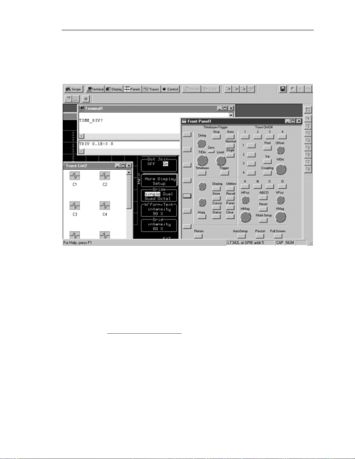
ScopeExploreris a highly practical PC-based connectivity tool that interfaces W ave runner to a PC that is
running Microsoft Windows, via the rear panel GPIB (IE EE 488) or RS-232 port. Specia llydes ig n ed by
LeCroy for its oscilloscopes, ScopeExplorer allows you to perform data and image transfers and other remote
operations from scope to PC with just a few key board strokes or mouse clicks. See Chapter 12, “Use
Waver unner wit h PC ,” for more about using ScopeExplorer w ith you r W ave runner scope.
S copeE xplorer now has a virtual front panel to allow full cont rol of remote scopes.
Activ eDSO w orks on any PC running Windows 95, 98 or NT, and enables you to exchange data with a
variety of Window s applications or programming languages that support the ActiveX standard, such as MS
Office, Internet Explorer, Visual Basic, Visual C++ and Visual Java. ActiveDSO hides the intricacies of
programming for each of these interfaces and provides a simple and consistent interface to the controlling
application. You can also visually embed ActiveDSO in any OL E automation compatible client and use it
manually without programming. You could, for example, generate a report by importing scope data straight
into E xcel or Word, analyze your wave forms by bringing them directly into MathCad, archive measurement
results “on the fly” in a Microsoft Access database, and automatetests usingVisual Basic, Java,C++, or
Excel (VBA).
Visit our websiteat http://www.lecroy.com/softwareto download these and other free softwa re applications.
LTXXX-OM-E RevB ISSUED: January2002 5
Page 14

F IRST T HINGS
Safet yFirst
OPERATE IN A SAFE ENVIRONMENT
Beforeinstallingyour Waverunner, ensurethat its ope rating
environment will be maintained within these parameters:
Temperature: 5 to 40 °C (41 to 104 °F)
Humidity: <80% RH (non-condensing)
Altitude: <2000 m (6560 ft)
Operation: Indoor use only
GET TO KNOW TH E WARNING SYM B O LS
Wherever these warning signs appear on the Waverunner’s front or rear pane ls, or in this manual, they alert you
to aspects of safety .
CAUTION: Refer to accompa n y ing
documents (for safety related information).
See elsewhere in this manual wherever
this symbol is present, as indicated in
the Table of Contents.
CAUTION: Risk of Electric Shock
On (Supply)
❘
: Waver un n erhas been qualified
NNOOTTEE:
to the following E N 6101 0-1 category:
Protection Class
Installation (Over voltage)
Category
Pollution Degree 2
Any use of the instrument in a manner
n o t specif ied by the manufacturermay
im pairthe instrument’s safe ty
pr o tection. Wav erun n erhas
design ed to make direct
measur em ents on thehumanbody .
N ever connect the Waverunner to a
livin g per son .
II
WARNING
WARNING
WARNINGWARNING
I
NOT
been
Standby
CAUTION
CAUTION
CAUTIONCAUTION
Do not ex ceed th e maximumspecified
inp ut voltage levels
Earth (Ground) Terminal
6 ISSUED: January 2002 L TXXX-OM-E RevB
Page 15
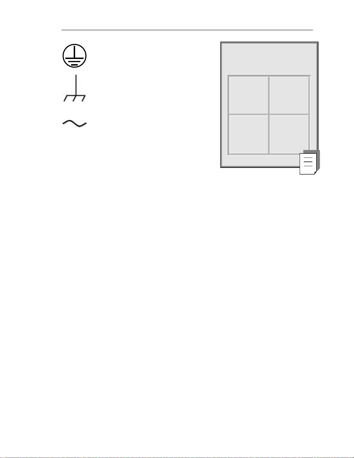
Protective Conductor Terminal
First
: W av erunnerautom atically
NNOOTTEE:
adapts to th eline v oltage presen t:
Chassis Terminal
Alternating Current Only
WARNING
CH O OSE T HE CORRECT POWER SOUR CE
W ave runn e r op e ra tes from a single-pha se, 115 V (90 to 132 V) or 220 V (180 to 250 V), AC (~) power sou rce at
45 Hz to 66 Hz.
No voltage selection is required because the instrument automatically adapts to line voltage. The power supply
of the oscilloscope is protected against short circuit and overload by one 5x20 mm fuse (T 6.3 A/ 250 V). See
next page for replacement procedure.
Denotes a hazard. If a WARNING is indicated on the instrument, do not proceed until its
conditions are understood and met (see also CAUTION).
115 V
(90–132V)
220 V
(1 8 0–25 0V)
45–66 H z
45–66 H z
MAINTAIN POWER GROUND
Maintain the groundline to avo id electric shock .
The current-carrying conductors cannot exce ed 250 V rms with respect to ground potential. Wave runner is
provided w ith a three-wire electrical cord containing a three-terminal polarized plug for line voltage and safety
ground connection. The plug’ s ground terminal is connected directly to the frame of the unit. For adequa te
protection against ele c trical haza rd,this plug must be inserted into a mating outlet containinga safety ground
contact. Set the pow er switch to STANDBY before connecting or disconnecting the powe r cord.
LTXXX-OM-E RevB ISSUED: January2002 7
Page 16
F IRST T HINGS
RE PL ACE WITH THE CORRE CT FUSE S
For con tinued fire protection at all line voltages, repla cefuses only w ith those of the specified typ eand rating .
Disconnect the powe r cord before inspecting or replacing a fuse. Open the fuse holder (located directly to the
left of the mains pow e r plug) using a small, flat-bladed screwdriver. Remove the old fuse and replace it w ith a
ne w5x20 mm fuse(T 6.3 A/250 V).
CLEAN YOUR WAVERUNNER (BUT LET US MAINTAIN IT)
Maintenance and repairs should be carried out exclusively by a LeCroy technician.
Clean only the exterior of your Waverunner, using a damp , soft cloth. Do not use chemicals or abrasive
ele m ents. Unde r no circumstance s allowmoisture to p e n etrate theoscilloscop e. To avoid elec tric shock s ,
disconnect the instrument from the pow er supply before cleaning .
CAUTION
Risk of electr ic shock. N o user
serviceable parts inside. Leave repair
to qualified person n el.
8 ISSUED: January 2002 L TXXX-OM-E RevB
Page 17

Up and Running
T
EXTC
o
t
h
C
t
r
o
l
n
o
P
e
r
i
t
e
M
GET TO KNOW YOUR WAVERUNNER – FRONT PANEL
First
On/
Stand-by
Display
enu Controls Timebase Controls
AUTO SE TUP
Channel 1 Channel 2 Channel3 Channel4
(Channels 3 and 4 on four-channel models only)
Floppy DiskDrive
AUTO
SETUP
ZERO DELAY SETUP STOP AUTO NORMAL SINGLE
DELAY LEVEL
RETURN
TOOLS
IME / DIV
PANELS
UTILITIES
DISPLAY
STANDBY
WAVE
STORAGE
SETUP
TIMEBASE
STATUS
TRIGGER
ZOOM + MATH
ZOOM
SCOPEMEASURE
ALL INPUTS
50 5Vrms
1M 16pF 400Vpk
CAT II
OFFSET
VOLTS / DIV
VmVnss
RESET
MATH
TOOLS
CLEAR
SWEEPS
Ω
Ω
AL
POSITIONPOSITION
ZOOM
PRINT
SCREEN
Ground
CHANNEL
SELECT
ANALOG
PERSIST
Controls
Trigger
Controls
Channel
Z
om and M a
on
s
A
al
g
CAL
s
s
enc
Waverunner main front panel cont rol s and features.
IN STALL AND POWE R UP
1. Before powe ring up, check that the local pow e r source corresponds to Waverunner’s power range (see
page 7).
2. Use the cable provided to connect the scope to the powe r outlet through its rear panel receptacle (see next
page).
3. Turn the scope on by pressing the On button at the bottom left-hand corner of the Wave runner front
panel (see above).
LTXXX-OM-E RevB ISSUED: January2002 9
Page 18
F IRST T HINGS
Before a displayapp e a rs , theinstrume nt w ill automaticallype rform hardw are andsoftw a reself-tests, followed
by a full system calibration. The front pane l STANDBY L ED w ill be lit during this seque nce. The full testing
procedure will take about 10 seconds, after which a display appe ars.
UTILITIES
4. Press
to display the UTIL ITIES on-screen menus.
5. Then press the button beside the menu
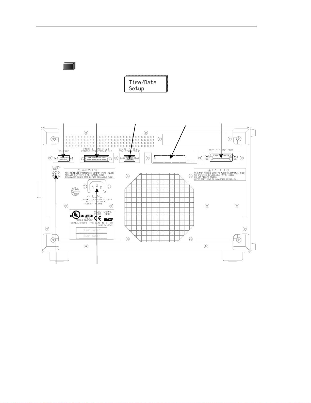
GET TO KNOW WAVERUNNER – BACKPANEL
RS-232-C Port
Centronics Port
External MonitorPort
to set thetimeanddate.
PC C ard Slot
(Memor y/H ard-Disk card )
GPIB Port
PowerInputBN C SignalOutput
Use the RS- 232- C and G PIB ports t o connect your Waverunner scope t o a comput er or terminal, the
ex t ernal m onitor port to display your waveforms on another monit or, and the C entr onics
port to
connect compatible print ers or other devices. U se the PC Card slot for the P C Memory Card and
port able H ard D isk opt ions, and t he BN C output for ex ternal clock signals.
10 ISSUED: January 2002 L TXXX-OM-E RevB
Page 19
TON
AV I G AT ETHROUGHMENUS
First
Menus
The menu button
Longer menus
Capitalized menus
The two menu knobs
Combin atio n s of kn o bs and buttons
or chan ges the variable, while the knob adjusts its value.
Menus are grouped
selectaparticularmenuoranitemonamenu.Travelupordowninthemenulist andchangethe
selecti on. Or change val ues and sett ings.
The darker, labeled buttons
to select the menus for initialization. When you press any one of these, it offers access to related
menus in it s gr oup.
such as enable you to perform actions or adjust settings.
beside each displayed men u controls that menu .
that span the breadth of two buttons are controlled by both buttons.
— for example — perform specific actions.
work together with the two menu buttons beside them.
control continuously adjustable variables. The button selects
and shown together according to their function. Press a buttonor turna knob to
PANELS
also play a role in menu selection:
—forexample—wasused
Menus withshadows
RETURN
Press
the previous menu display.
to return
to a shadowed m en u . A nd use this button w hen ever you wish to go back to
Arrows on t he side of a long menu
Press one or the other of these menus’ butt ons to move in the desired direction, and to view or select
any menu it em not displayed. A rrows disappear when you reach the beginning or end of the menu
list.
LTXXX-OM-E RevB ISSUED: January2002 11
lead to other menus: Press their buttons to display those others.
indicate that you can scroll up or down the menu list.
Page 20
F IRST T HINGS
IN IT IAL IZE
Initializeyo u r W a v erunne r scopeto its basic default w ave form displaysettings:
PANELS
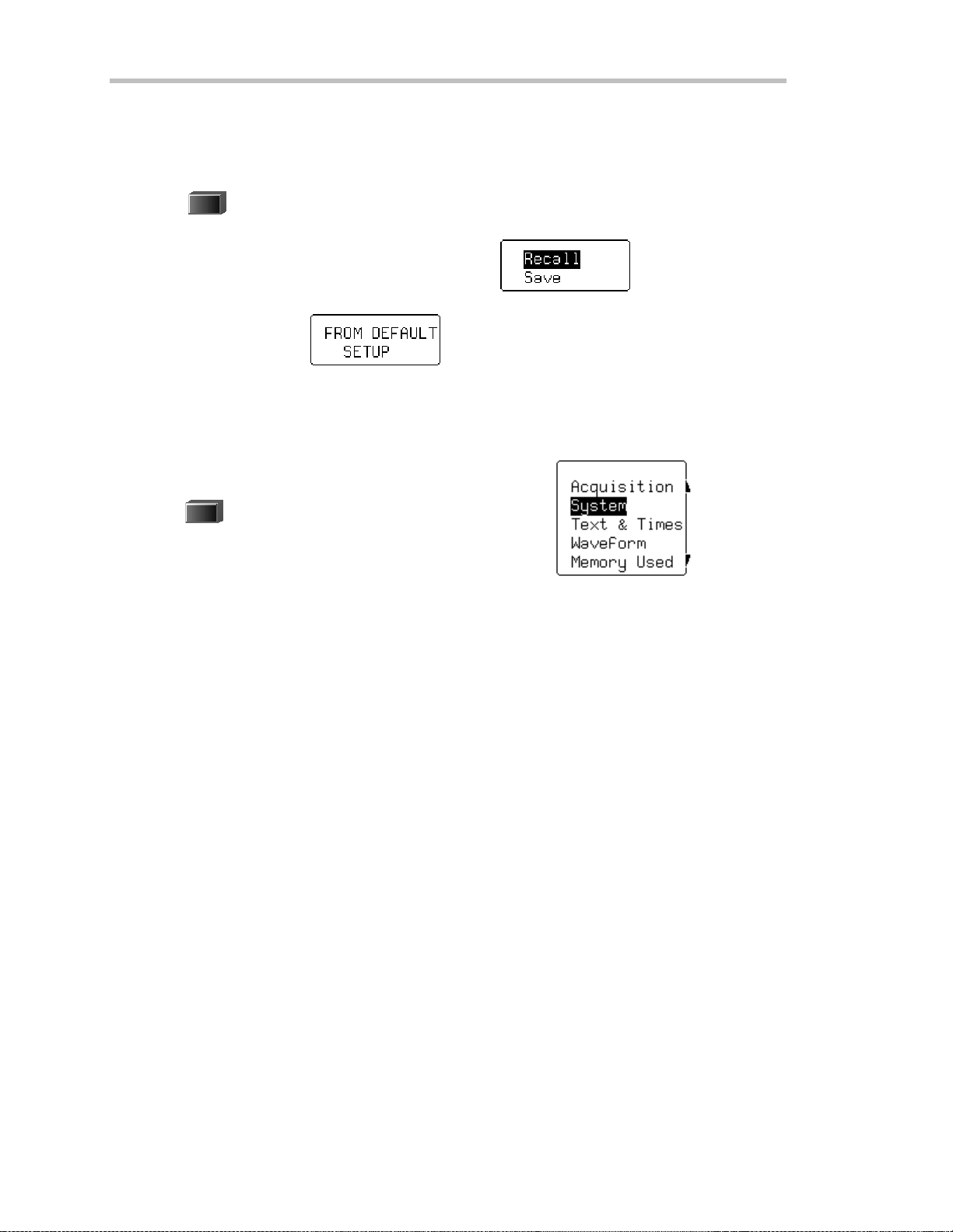
6. Press
7. If Recallis not selected, press the button once to select it:
8. Then press the button beside .
Initialize to Wa verunner default settings whene ver you wish to clear your settings and make a fresh start on a
newmeasurement.
CHECK YOUR WAVERUNNERSYSTEM
SCOPE
STATUS
Press
9.
10. Press the top button to highlight and select Syst em . The screen will show your W ave runner’s serial
nu mb er, the ve rsion of s oftwa reinstalledandthe date of its relea se, as w e ll as a full list of you r currently
installed software and hardw are.
Contact L eCroy customer service immediately if any of the options you ordered have not been installed.
to display the PANEL SETUPS menu group.
to show the STATUS menus.
12 ISSUED: January 2002 L TXXX-OM-E RevB
Page 21
First
ADD AN OPTION
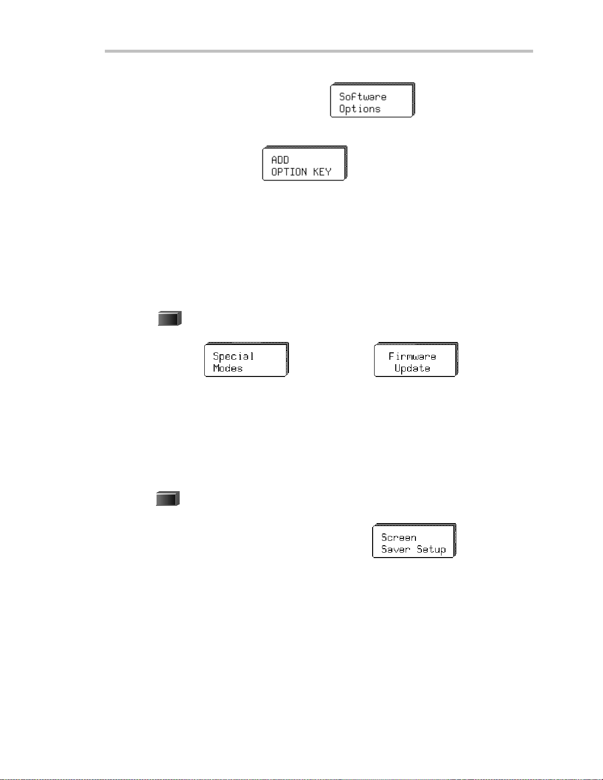
This menu will also be displayed when you select System:
Use it to install newoptions — w ithout the need to return your Waverunner for a refit.
1. Press that menu’s button to display
2. Then press that menu’s button to display the ADD OPTION menus. Use them whenever you wish to add
a Wa verunner option by means of a special code. Contact your L eCroy sales or service center to obtain the
code.
UPDATE TO THE L ATEST FIRMWARE
Your Waverunner comes with the latest firmware installed. But to takeadvantage of our continuous
improvement, contact us to obtain a floppy disk or card containing the latest firmware. Then use these menus
to install it:
UTILITIES
1. Press
2. Press the button for
to display the UTIL ITIES menus .
, then for the one for .
3. Place the floppy or card in the Wa verunner and press the buttonsto select Floppy or Card and then
Update Flash. The ne wly installed firmware will app e ar on theSystem Status screen (seeabove).
Yo umayalso downloa dthe firmw a re from the internet, usingScope Exp lo rer .
SAVE THE SCREEN (AN D ENERGY)
Enable or disable your Waverunner’s screen saver:
DISPLAY
1. Press
to show theDISPLAY SETUP menus.
2. Press the button for “More Display Setup” to access this menu:
LTXXX-OM-E RevB ISSUED: January2002 13
Page 22
F IRST T HINGS
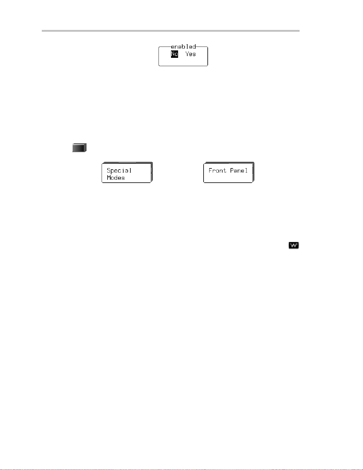
3. Press its button, then select Yes or Nofrom
When enabled, the built-in screen saver is activated 10 minutes after the last use of a front panel control. This
is a complete display shutdown of the internal screen — an “E nergy-Saver.” The front panel L E D light will
indicate when the scope is in the screen-saving STANDBY state. Press any front panel button to restore the
screen.
DO YOU PREFER YOUR CONT ROL S WITH SOUND AND AUTO-REPEAT?
Have your buttons and knobs repea t their actions and make an audible sound w hen used:
UTILITIES
1. Press
2. Press the button for
3. Make your preferences by means of the USE R PRE F’S menus displayed.
With Pushbutton auto-repeat On, all front panel buttons, w hen pressed and held in, will move the selection
au toma ticallyand seq u entiallythrough all item s in a men u .
With audible feedback for buttons and knobs On, an audible “click” will sound when any front panel button is
presse d or anyknob is turned.
to display the UTIL ITIES menus . These you will find useful for a variety of functions.
, then the button for .
14 ISSUED: January 2002 L TXXX-OM-E RevB
Page 23

P
P
T
AARRT
O
O
E
NNE
G
T his part of the manual covers the main Waverunner features and explains, step by step, how to use
them. You’ll get to knowyour scope and start wor king with it quickly and effectively. Capture and view
w av ef o rm s. Zoomand scroll. Learntheart of display . Use mathandmeasuremen t tools. Document
your work.
G
E
E
T
T
TII
T
N
N
G
G
T
SST
A
A
R
R
T
T
E
E
D
D
LTXXX-OM-E RevB ISSUED: January2002 15
Page 24

C HAPTER O NE:
In thi schapter, see how
To select the input signal channel
To use menus and controls for basic operations
To find yo urwayaroun d th e display
To adjust th e time base, gainand po sitio nof thesignal
To zoom— m anually and automatically
To set up the time base
To set signal coup l in g
To calibrate and use thepassive pr o be
To set up the CAL and BN C outputs
Catcha NewWav e
16 ISSUED: January 2002 L TXXX-OM-E RevB
Page 25
C HAPTER O NE
Catch a New Wav e
ViewYo ur W aveform
Takethesesteps to captureandviewyour signal; set timeand voltsper division; zoomand auto-scroll:
1. Connect your signal to the Waverunner (Channel 1 input for this example).
AUTO
SETUP
2. Press the blue
for display of the input signal. Press it again to confirm the action.
buttonto automaticallyset the(Edge) trigger level, timebase, and vertical settings
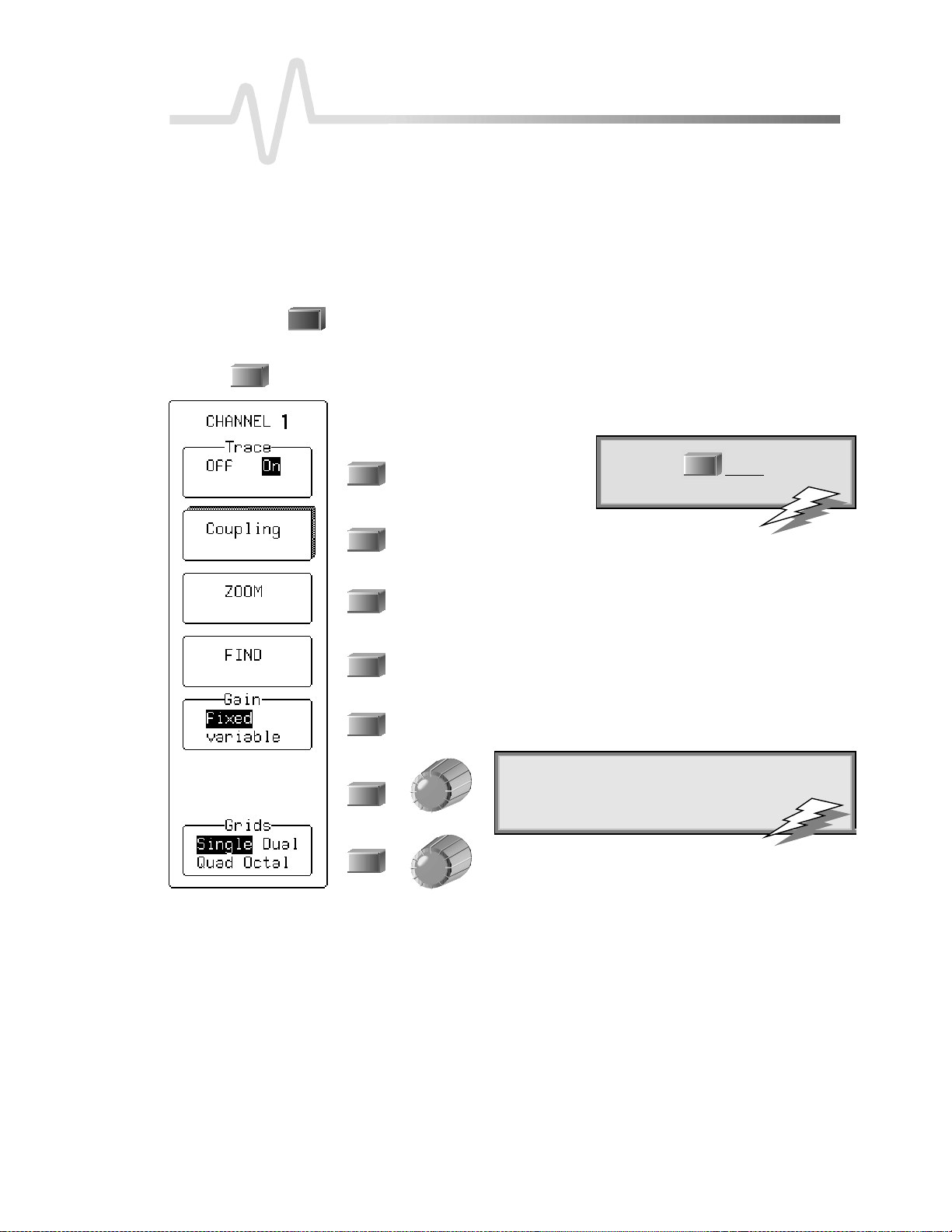
3. Press
1
to select CHANNEL 1 and displa ythe basic W a v e runn e r menus .
4. Use these menus in the steps on the following pages to adjust the signal’s trace
on the screen.
To turn Channel 1 on or off.
To access the CHANNEL Coupling menus. See page 24.
To au toma ticallymakea zoomed traceof thesigna l.Use thevertical
POSITION knob to mov ethe traceso that it is clearly visible . Use the
ve rtical ZOOM kno b to adjust its e x p a n sionvertically. Seepa g e22.
To automatically set gain and offset, and “find” the signal.
To select fixed or variable gain. Select “variable” to control the channel’s
gain continuously. See page 20.
: With AUTO SETUP yo u can automaticallyset
TTIIPP:
up signals in the 5 mV to 40 V range with a
frequency of ≥≥≥≥50Hz and a duty cycle
as small as 0 .1%.
TTIIPP:
:Press
1
channel on or off.
tw i ceto turnthe
To select the grid styleandnum b e r.Next pag e : Single
grid. See also Chapter 3, “ D isplay Your S ignal.”
LTXXX-OM-E RevB ISSUED: January2002 17
Page 26
P ART O NE: GETTING STARTED
TOF
IN DYOURWAY AROU N D T H EWAVERUNNERDISPLAY
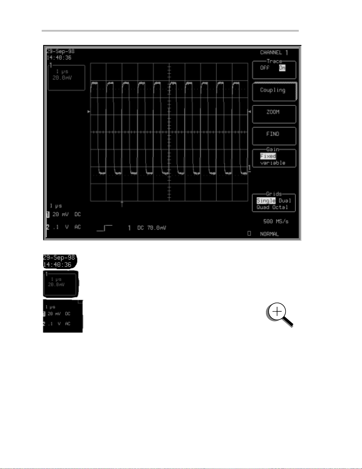
Real-T ime Clock field:
displays the current dat e and time.
Displayed Trace L abel
time/ div and volt s/ div settings, and cursor readings where appropriat e.
Acqu isiti on S ummary field:
attenuation, and coupling for each channel, with the selected
channel highlighted.
powered by a battery-backed real-time clock , it
indicat es each channel or channel displ ayed, the
timebase, volts/ div, probe
18 ISSUED: January 2002 L TXXX-OM-E RevB
Page 27

C HAPTER O NE:
Catch a New Wav e
Trigger L evel
the trigger voltage level relative to ground level.
Trigger Delay
Trigger Status field
(A U TO, N OR M A L , SI N GL E , S T OPPE D ). The sm all square icon flashes
to indicate t hat an acquisition has been made.
Trigger Configuration field
trigger, an d informa tion on the trigger’s source, slope, level an d coupling, an d
other information when appropriate.
Trace and Ground Level
mar k er.
Other display areas include the
time and frequency relativeto cursors, and a
specialmessages.Formoreaboutthedisplay,seeChapter3,“DisplayYourSignal.”
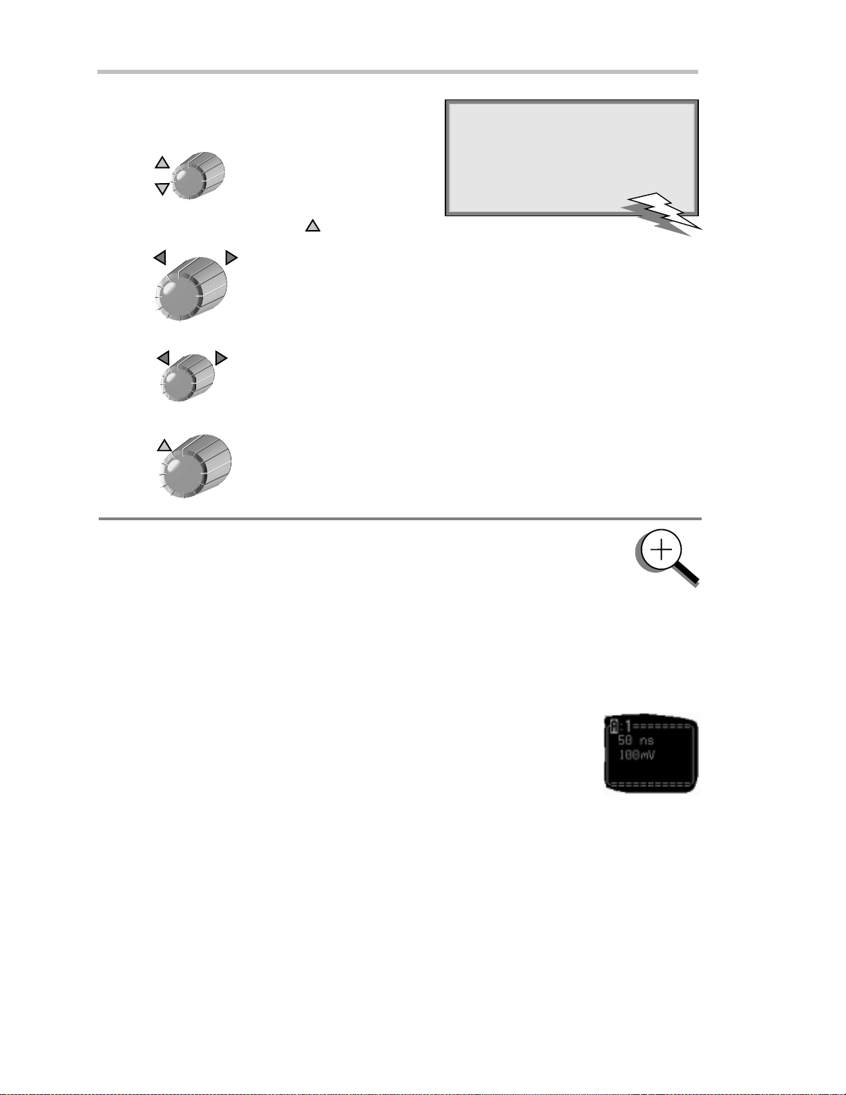
USE TIME / DIVTO ADJUST T HE TIME BASE
Time and Frequency field
TIME / DIV
arrows on both sides of the grid that mark
is an arrow indicat ing t he t rigger time relati ve to the trace.
shows sampl e rat e and trigger re-arming status
cont ai ns an icon indicati ng the type of
shows the trace num ber and groun d level
, located below the grid and stating
M essag e field
placed above the grid and reserved for
NNOOTTEE:
:AUTO SET UP operatesonly
on channels that are turned on,
unless no channels are turned on.
T hen all channels will be affected.
sns
When more than one channel is
turned on, the first channel in
numerical order with a signal
5. Turn
to adjust the timebase as desired.
app lie d to it w illbe autom atically
set upforedgetriggering.
Thetime pe r division is set in a 1–2–5 sequ e n ce. Wa verunne r au toma ticallyadap ts itself to use the max im u m
sampling ratewhenever thetimebaseischanged. Theselected time/divsetting is shownin thetracelabel at the
topleft portion of t hescreen,andthesamplingrateinthetrigger statusfieldat thebottomright-handcorner.
LTXXX-OM-E RevB ISSUED: January2002 19
Page 28
P ART O NE: GETTING STARTED
ADJUST SENSITIVITY AND POSITION
VOLTS / DIV
VmV
6. Turn
sen sitivity. The volts/ div setting is shown in the
Channel 1 trace label.
The next two steps can be taken (if not already ) whe n you
wishto finetunethevertical gain and get abettervertical
resolution:
7. Fine tune the vertical gain by selecting “variable” from
theGainmenu(seepage17).
8. Now turn the VOLTS / DIV knob through several
completerotations, so that theentiresignal reaches
from top to bottom of thegrid. Filling the grid in this
way, y o ucan use the full rangeof availab ledigitizing
lev e ls.
OFFSET
tore duc ethevertica lga in
UTILITIES
TTIIPP:
:Press
to select Speci al
Modes. T hen select the Channels menu
to choose
In: to set the offset of again
(VOLT S/ DIV) change in volts or vertical
divisio n s (this is in vo lts, by default).
Automatic Recalib ration: to turnthis
featur eonoroff (default is “On ”). “Off”
mayspeed capture, but time calibrationis
no t certain dur in g th e capture perio d.
Global BWL : to control the global
bandwidth limit. When O n, the chosen
bandw idth(see page 24) applies to all
channels. When O ff, a bandwidth limit
canbe set ind ividuallyforeachchannel .
9. Use
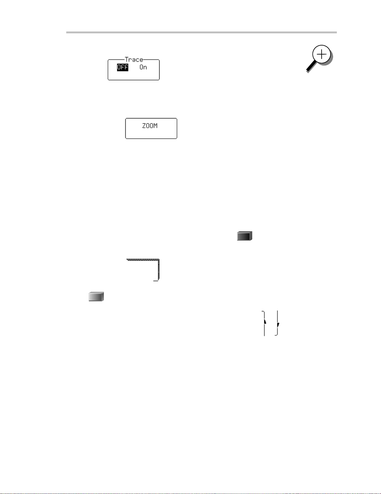
ZOO M AND SCROLL AUTO MAT ICAL LY
Use ZOOM to see more detail on your signal. The display will show the original signal and its zoomed copy .
10. Press
11. Press
12. Press the button for:
The menus shown on the next page will be displayed.
A
A
to center the wave form on the grid.
todisplaytheTRACE Amenus(todisplayTraceB,C,orD,pressitsbutton).
again or thetopbuttonto display thetraceand its label. (Do t hesameto turnoff a trace.)
:Togobacktothedefault power-up
TTIIPP:
settings, simultan eo u slypr ess th e second
and fifthmenu buttons fromthetop, an d
1
th e
CHANN EL SELECT 1butto n.
20 ISSUED: January 2002 L TXXX-OM-E RevB
Page 29
C HAPTER O NE:
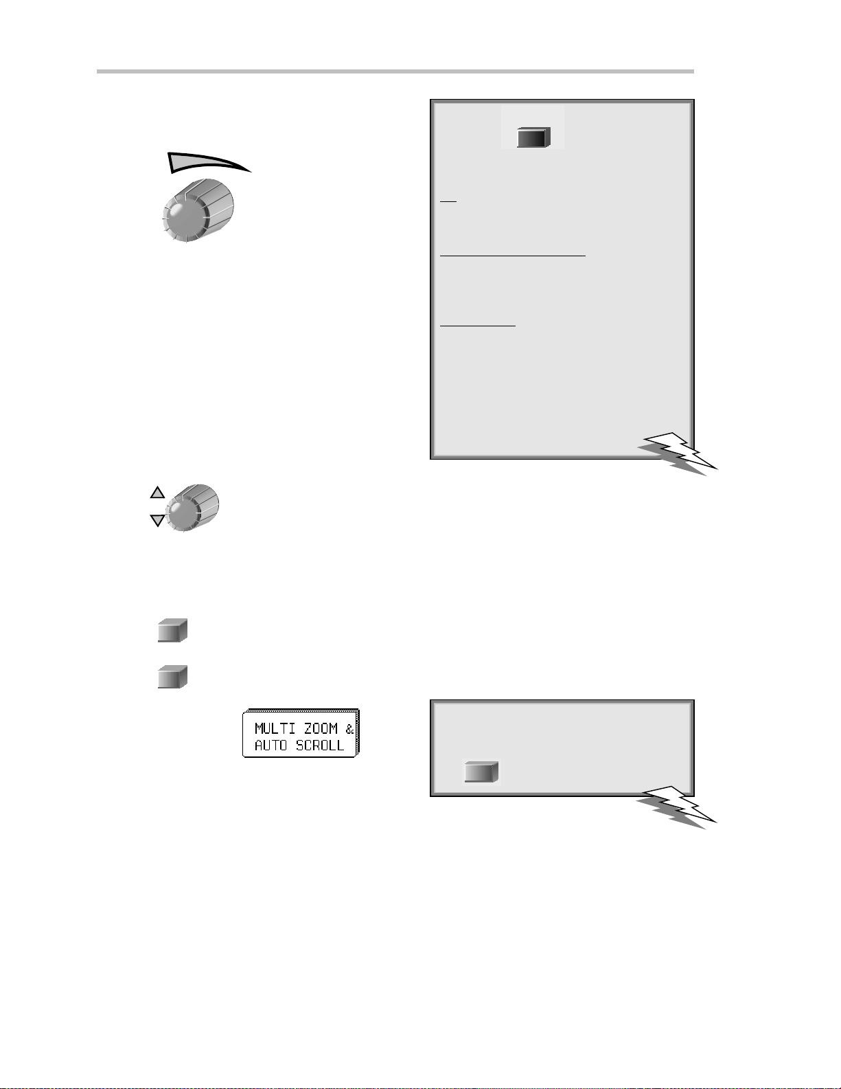
13. Use these menus to scroll back and forth through the full length of one or all of your zoom copies.
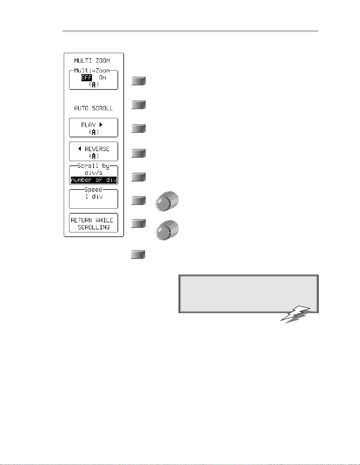
MULTI-ZOOM un ifies the control of a ll zoom traces,wh ileAUTO-SCROLL
w alks the zoom trace or traces across the referenced trace.
Whe nOff, only the active zoom trace is controlled. When On,all
disp la yedzoom traces(A, B , C, D) are simultan e o u slycontrolled
(automatically) with Auto Scroll and (manually) with the horizontal
ZOOM and POSITION knobs. See the next page for more on
Multi-Zoom.
To scroll the zoom trace from right to left of screen. When playing,
the menu is labeled “STOP (PLAYING)” : Press to stop.
To scroll the zoom trace from left to right of screen . When play ing,
the menu is labeled “STOP (RE V E RSIN G)”: Press to stop.
To scroll bydivisions per second or number of divisions. Use div/s to
scroll continuously for viewing. Use number of div for waveform
processing ,especiallyPass/Fail testing. Whe n processingis complete ,
the display will be updated by the number of divisions set.
Catch a New Wav e
To set scroll spee d, using the knob . When scrolling by
divisions, 10 div w ill step the zoom trace “grid-page” by
“grid-page ” across the length of the referenced trace .
To return to the TRACE A menus, while continuing to
scroll, by pressing the menu button.
RETURN
To stop scrolling and return to the previous menu displaye d.
: Con siderzoo mas anextra time base th at offe r s
TTIIPP:
alternative sw e epspeeds. Y o u can displayas man y
as four zooms at once.
LTXXX-OM-E RevB ISSUED: January2002 21
Page 30
P ART O NE: GETTING STARTED
USE TH E POSITION AND Z OOM CONTROL S
POSITION
: T he smaller Waverunner knobs
TTIIPP:
arerate sen sitive: the faster y o u rotate
th e m, th e gre a terthechange th at
results per increment.
14. Turn
When using more than one grid, turn POSITION tomovetracesfromonegridtoanother.
ZOOM
15. Turn
POSITION
16. Turn
ZOOM
17. Turn
to placeTrace A verticallyonthegrid.
to adjust the expansion factor and increase the amount of zoom.
to movethezoomed regionof thetrace.
to vertically expand, or reduce, the zoom trace.
TOZ
OOM ANDMULTI-ZOOM
You can zoom several traces from a single waveform to obtain precise timing
measurements and improve the time resolution on your displayed waveform. F or
instance, on a w aveform composed of two pulses separated by a long delay, you cou ld
make Trace A a zoom of the first pulse, and Trace B a zoom of the second.
Multi-Zoom
traces, or two or more regions of t he same trace, simultaneous l y. W hen you act i vate mul t i-zoom,
the horizontal zoom and position controls apply to all displayed t races — A, B, C, and D —
allowing you to view similar sect ions of different traces at t he same t ime. The vertical sensit ivity
cont rol s stil l act individual ly on the t races.
When trace labels have dotted top and bottom edges, lik e the one at right, this
ind icates that their traces are mu lti-zoomed.
allows you to move the zoomed region of the w aveform along two or more different
22 ISSUED: January 2002 L TXXX-OM-E RevB
Page 31

SET UP THE TIMEBASE
SETUP
TIMEBASE
18. Press
and access the TIMEBASE menu s .
C HAPTER O NE:
Catch a New Wav e
19. Use these menus to set up the timebase in single-shot mode. See Chapter 7,
“A Q uest ion of T i mebase,” for more on the sampling modes.
Single-Shot samp lin gdispla ys datacolle cte ddu ringsucce ss iv esingle -sh o t
acqu isitions from the input channels — capture nonrecurring, or very low
repetition-rate events, simultaneou sly on all input channels.
To select Internalor external — ECL, 0V, TTL — clock modes.
Selec t internal unle s s using an externa l clock signal. SeeChapter 7, “A
Question of T imebase,” for external clock. The LT364 series has
a “Channel Use” menu below “Sample Clock” (see “Pairing
Channels” in Chapter 8).
To switch sequence mode Onor Off.Usetheknobto
choose the number of segme nts. See Chapter 7, “A
Question of T imebase,” for sequencesampling.
To select the maximum number of samples to be
acquired, using the menu knob; and, to set the default
50k,using themenubutton.
LTXXX-OM-E RevB ISSUED: January2002 23
Page 32

P ART O NE: GETTING STARTED
SET THE COUPLING
20. Press
1
and then the button for to display the coup lingmen u s.
21. Use these menus to set input signal coupling and grounding, the channel
bandw idth limit, and the probe attenuation.
Selects the signal coupling.
Moves your selection dow n the list. When at the bottom, as here, the
dow n arrow disappears and this button becomes inactive.
PressNORMAL to set offset, volts/ div, and input coupling to display
ECL signals. Press again; settings for TTL signals are given. Press a
thirdtime; settings will return to thoseof the last manual setup.
Press to turn the bandwidth limit Offor reduce the bandwidth to
200 MHz or 25 M Hz. Reduces signal and system noise and prevents
high -frequency alias ing. Global BWL mea ns that the limit set will
ap p lyto all cha nn els. BWL mea ns tha t a limit can be set individua lly
for each channel. See the TIP on page20 for howto set these, using
SPECIAL MODES.
To set the probe attenuation factor for the input
cha n nel. Thebuttons scroll up or dow n , whilethe
knobs scroll the selector up and down the list. LeCroy’ s
ProBus system automatically senses probes and sets
their attenua tion. This menu then changes to indicate
thetypeof probe attachedand its attenuation factor.
See the following pages for more on probes and
ProBus.
NNOOTTEE:
:
AC position: signals are coupled capacitively, the input signal’s DC component is blocked, and
signal fr equencies below1 0Hz arelimited.
DC position: signal frequency components are allowed to pass through, and an input impedance
of either1MΩΩΩΩ or 50 ΩΩΩΩ canbe selected. The max im umdissipationinto 50ΩΩΩΩ is 0.5 W. Whenever
this is attain ed, inp uts willautomaticallybe grounded. “Gro unded” w ill be h ighligh ted in th e
“Coup lin g” men u and an ove rl oad message will be displayed in the Acquisition Summ ar yfield.
Reset by remo v in g thesignal fro mth e inp ut and reselecting “DC50 ΩΩΩΩ.”
24 ISSUED: January 2002 L TXXX-OM-E RevB
Page 33

SETUP FOR CAL AND BNC SIGNALS
UTILITIES
1. Press
.
C HAPTER O NE:
Catch a New Wav e
2. Press the button to select
and display the CAL BNC OUT menus.
3. Use these menus to choose the type of signal put out at the front CAL and
rear BNC signal outputs. Set the frequency , amplitude, and pulse shape of
thecalibrationsignal.
To set the typeof signal from the rear BNC connector.
To reset the CAL output to its default state: a 1 kHz 1 V square wave.
TheWave runn e r au toma ticallysets the calibra tion sign a l to its de fault
when switched on.
To select the form of the calibration signal.
To set the pulse level for the CAL output (range: −1.00 to
1.00 V), using theknob.
To set the desired frequency of a CAL signal in the range
500 Hz to 1 MHz,usingtheknob.
LTXXX-OM-E RevB ISSUED: January2002 25
Page 34

P ART O NE: GETTING STARTED
TOC
ALIBRATE THEPASSIV EPROBE
Your Waverunner scope comes wit h a L eC roy passive probe for each channel .
First.
Second.
Third.
Things”).
Fourth.
T he CA L signal w ill be a 1 k H z square wave, 1 V p– p.
Fifth.
Sixth.
Seventh.
Eighth.
N inth.
T ur n on your Waverunner scope.
Insert the probe lead in the Channel 1 input.
Connect the probe t ip t o the C A L out put (s ee front panel illust rat ion i n “ F irst
Attach the lead’s alligator clip t o the ground ring indicated by ,locatedbelowCAL.
UTILITIES
Press
Press to select and set the amplitude level.
Nowselect to set the frequenc y in the ran ge 500 H z to 1 M H z.
S et channel coupling to D C 1 MΩusing “ C oupling” (see previous page).
Press
1
, then the button to select
to turn onC hannel 1.
AUTO
SETUP
T enth.
I f overshoot or undershoot of the displayed signal occurs, adjust the probe by inserting the small
screwdriver, supplied with the probepack age, into the potentiometer on the probe head and turning it
clock wise or counterclock wise to achi eve t he opt imal square wave contour.
Press
twice.
26 ISSUED: January 2002 L TXXX-OM-E RevB
Page 35

C HAPTER O NE:
Catch a New Wav e
HOWPROBUSH
L eCroy’s ProBus probe system provides a com plete measurement solution from probe
tip t o oscill oscope display.
ProBus allows you to control transparen t gain an d offset directly from your front panel —
particularly useful for voltage, differential , and current active probes. It uploads gain and offset
correction factors from the ProBus E PR OM S , and automat ical l y compensates to achieve fully
calibrated measurements.
T his int ell igent interconnect ion bet ween your Waverunner scope and a wide range of accessories offers
important advantages over st andard BN C and probe ring connections. ProBus ensures correct input
coupling by aut o-sensing the probe t ype, eliminat ing t he guesswork and er rors that occur when
at tenuation or amplification factors are set manually.
ELPSYOU
: U se Waverunner’s rear panel BN C signal output to provide a
TTIIPP:
pulse:
ForPass/Fail testing
At the occu r renceof eachacceptedtri ggerev e nt (TriggerOut)
Whenthe scope is r eady to accept a trigger event (Trigger Rdy)
LTXXX-OM-E RevB ISSUED: January2002 27
Page 36

C HAPTER T WO:
In thi schapter, see how
Tocontro ltriggers
Toset up anEdge tr igger
Tore-armtriggering
To determ in e level, coup lin g and slope
To use Win do wtrigger
To obtaina sum m ar yof you rtrigger and systemstatus
Simpl yTrigger
28 ISSUED: January 2002 L TXXX-OM-E RevB
Page 37

C HAPTER T WO
SimplyTrigge r
Edge Tr iggeronSim pl e Sign als
Wa verunner uses many wave form capture techniques that trigger on features and conditions, which you define.
These triggers fall into two major categories:
Edge — activated by basic wa veform features or conditions such as a positive or negative slope, and
holdoff
SMART Trigger — sophisticated triggers that enable you to use basic and complex conditions for
triggering. SeeChapter 8, “Trigg e r Smart.”
Use the E dge trigger type for simple signals, and the SMART Trigger type for signals with rarer features such
as glitches .
CONTROL TRIGGE RING
DELAY
Horizontal: Turn
Yo ucan adjust the trigge r’s position from 0% to 100% pre-trigger,from left to right on the grid. DEL AY can
also be used for setting the post-trigger, in time units, up to 10 000 divisions, in increments of 0.1 division.
The trigger location is shown by the arrow at the grid bottom, as
shown here at near right.
Post-trigger de la yis lab eledin the trigge r delay field,wh ere the
arrow becomes horizontal, as shown here at far right.
TRIGGER LEVEL
Vertical: Turn
Turn this knob to adjust the level of the trigger source or the highlighted trace. Level defines the source voltage
at w hich the trigger will generate an event — a change in the input signal that satisfies the trigger conditions.
Arrows on both sides of the grid showthe threshold position. But these arrow s are only
visible if the trigger source is displaye d and the source signal DC coupled.
to adjust the trigger’s horizontal position.
to adjust thetrigger’svertical threshold.
LTXXX-OM-E RevB ISSUED: January2002 29
Page 38

P ART O NE: GETTING STARTED
SE T UP AN EDGE TRI GGER
SETUP
1. Press TRIGGER
to access thesemenus:
Use them to select the trigger source, the source’s coupling, the slope — positive
or negative — and the amount of trigger holdoff bytime or events.
1. Select “Edge” or “SMART”: “Edge” is selected by default.
: Once set, trigger level and coupling pass unchanged from
TTIIPP:
tr i ggertype totriggertyp e foreachtriggerso urce.
2. Select the trigger source. This could be a signal on a channel, the
linevoltage that powers theWaverunner, or the EXT BNC
connector.
3. Sele ct the cou p lin gfor the trigge r source.
4. Place the trigger point on the positive or negative slope of the
selected source, or choose to define a window.
Whe n Windo wis selected from the above menu, a
menu appears he rethat allow s youto define the
window ’ s size. See page 33.
To hold off from triggering for a defined time, or
numberofevents,afteraparticulartriggerevent.Use
this buttonto select Time or Events,andtheknobto
set the value . Offdeactivates the holdoff. See Chapter 8,
“Trigger Smart .”
DELAY
5. Turn
TRIGGER LEVEL
6. Turn
to adjust the trigger’s horizontal position, and the amount of pre-trigger, as desired.
to adjust the trigger voltage level.
30 ISSUED: January 2002 L TXXX-OM-E RevB
Page 39

TOD
ETERMINETRIGGE RLEVEL,COUPL ING AN DSLOPE
C HAPTER T WO:
Simpl yTrigger
Level
a change in t he input signal that satisfies the trigger conditions. The selected t rigger
level is associated with the chosentrigger source.
Trigger level is specified in volts and normally remains unc han ged when you change the vertical gain
or offset. The ampl itude and range of the trigger l evel are limited as follows:
C oupling
trigger level, you can select the coupling independently for each source. C hange the trigger source and
you can chang e the coupling. You can choose from these coupling types:
bursts or where t he use of A C coupling would shift the effective trigger level .
levels are rejected and frequen c ies below 50 H z
attenuated.
capacitive high-pass filter network, D C is rejected
an d signal frequenc ies below 50 k H z are attenuated.
For stable triggering on m edium to high frequenc y
signals.
circuit, and a low-pass filter network attenuates
frequencies above 50 kH z; used for triggering on low
frequencies.
definesthesourcevoltageatwhichthetriggercircuit willgenerateanevent:
±5 screen divisions wit h a channel as t he trigger source
±0.5 V with EXT as thetrigger source
±5 V with E XT/ 10 as the trigger source
N one with L IN E as t he trigger source (zero crossing is used).
refers to the type of signal coupling at t he input of t he t rigger circuit. A s with the
DC: A ll the signal' s frequency co m ponen ts are coupled to the trigger circu it for high frequency
A C: T he signal is capacitively coupled, DC
LF REJ: Thesignaliscoupledthrougha
HF RE J: Signals are DC coupled to the trigger
e
p
o
l
S
e
v
Triggerlevel
i
t
i
s
o
P
H F : U se only when needed for triggering on
high-frequency repetitive signals. H F is
automatically overridden and set to A C w hen
incompatible with trigger characteristics such as those
of S M A RT T rigger.
Slope
transition used for generating a particular trigger
event. You c an choose a positive or neg ative slope.
L ike coupling, t he selected slope is associat ed with
the chosent rigger source.
LTXXX-OM-E RevB ISSUED: January2002 31
determines thedirection of the trigger voltage
F igure 1. E dge trigger work s on the selected
edge at the chosen level. The slope — positive
here — is highlighted on the trigger icon .
Trigger
Page 40

P ART O NE: GETTING STARTED
TORE-A
Three trigger re-arming modes — AU TO, N OR MA L , and SIN GL E — are
available for all types of triggers. I n addition, S T OP c an c els the ca pture in all
three modes.
Press
soon after. But if a signal does occu r, Waverunner behaves as if in N OR MA L mode.
Press
trigger. If there is no validtrigger, thelast signal is retainedand the warning “S L OW
TRIGGE R” is displayed in the t rigger s t atus field.
Press
display the signal and stop capturing. If no t rigger occurs, you can press this button again to
manual l y trigger the s cop e.
Press
ST OP to prevent capture of a new signal, or while a sing le-shot c apture is unde r way to k eep the
last captured signal.
RM ATRIGGE R
AUTO
to activate A U T O m ode: the trace will automatically be displayed if no trigger occurs
NORMAL
to enter NOR M AL mode and continuously update the display while there is a valid
SINGLE
to enter SI N G L E mode: the Waverunner will wait for a single trigger to occur, then
STOP
to halt the capture made in AU T O, N OR M A L or S IN GL E re-arming modes. Press
TOR
ECOGNIZETRIGGE RICON S
T rigger icons al low immediate on-screen recognition of the curr ent trigger conditions. T here is an
icon for each trigger. The more heavily marked transiti ons on the icon indicate the slope on which the
trigger will begenerated. T he icons are annotat ed with information on the trigger settings.
This icon, for example, represents an E dge trigger set up to trigger on the positive slope, at a level of
0.008 V , with a holdof f time of 50 ns.
32 ISSUED: January 2002 L TXXX-OM-E RevB
Page 41

C HAPTER T WO:
USE WIN DOW TR I GGER
Define a region whose boundaries extend above and below the selected trigger level. A trigger event w ill occur
whe n the signal leaves this w indow region in either direction and passes into the upper or lower region (Fig. 2).
The next trigger will occur when the signal again passes into the windowregion.
Simpl yTrigger
1. Sele ct
2. Then use
A bar at the left-hand side of the grid will visually indicate the window’s height.
Trigger Le vel
.
to define the size of the windowregion.
Upper Region
LowerRegion
WIN DOW REGION
Time
Triggers
F igure 2. W indow T rigger: triggers w hen the signal leaves the window region. The arrows indicate
where tr i gger s occur when t he s i gnal l eaves the wi ndow r egion.
LTXXX-OM-E RevB ISSUED: January2002 33
Page 42

P ART O NE: GETTING STARTED
T RIGGER SOURCE
Thetriggersourcemaybeoneof thefollowing:
The acquisition channel signal (CH 1, CH 2, CH 3 or CH 4) conditioned for the overall voltage gain,
coupling , and bandwidth.
The line voltag e that powers the oscilloscop e (LINE). This can be used to provide a stable disp la y of
signals synchronous w ith the powe r line. Coupling and level are not relevant for this selection.
The signal applied to the EXT BNC connector (EXT). This can be used to trigger the oscilloscope within
arangeof
Level
Level defines thesource voltageat whichthe trigg er circuit w ill generate an eve nt (achange in the input signal
that satisfies the trigger conditions). The selected trigger level is associated with the chosen trigger source. N ote
that the trigger level is specified in volts and normally remains unchanged when the vertical gain or offset is
modified.
TheAmplitudeand Ran g eof the trigge r level are limitedas follow s:
±5 screen divisions with a channel as the trigger source
±5VwithEXT/10
none with LINE as the trigger source (zero crossing is used)
±0.5 V on E XT and ±5 V with EXT/10 as the trigger source.
Note:
Note:On ce specified, Tr igger Leveland Couplin g are theonly
Note:Note:
pa ramete rs that passunchangedfr omtri ggermode to tri ggermode
foreach trigger source.
34 ISSUED: January 2002 L TXXX-OM-E RevB
Page 43

C HAPTER T WO:
Simpl yTrigger
OBTAIN A TRIGGER STAT USSUMMARY
Display a summary of the status of you r trigger, as well as timebase , vertical sensitivity , probe attenuation, and
offset and coupling for each channel.
SCOPE
STATUS
1. Press
to show the STATUS menus.
2. Press the button to select Acquisition .
PRINT
SCREEN
TTIIPP:
:Press
to documen t y ourstatus
sum m ar yandmakea h ard copy .
PANELS
Press
when you have a setting you wan t to
reuse(seethenextchapterformoreonthis).
Press the S COPE S TA T U S button for acc ess to full-screen summaries of your Waverunn er’s system
status and other functional status.
See Chapter8, “Trigger Smart,” for mor e about Edge triggerand all about the SMART Triggertypes.
LTXXX-OM-E RevB ISSUED: January2002 35
Page 44

C HAPTER T HREE:
In thi schapter, see ho w
To viewsignal changes overtime
To set up the displ ay
Disp layYou rSignal
Toset up forAnal og Persis tence
Tochoose a grid style
To save and recal l pane l setups
36 ISSUED: January 2002 L TXXX-OM-E RevB
Page 45

C HAPTER T HREE
DisplayPersisten ce
Displ ayYourSignal
You can use Wa verunner colors and tools to display your
signal on the screen.
View one,two, four, or eight grids and up to eight traces
(depe nding on model) at the same time. Adjust display and
grid intensity. Choose from several grid styles .Or fill the
entire screen with your waveforms using F ull Screen.
Yo ucan persona lizeyour W ave runner displa y, wh ile
managing color and screen intensity automatically. The
displayed signal and all related information share identifying
colors chosen by you. Show signals and traces opaquely or
transparently, sothat overlapping object s — traces over
traces,tracesover grids — are always visible.
Other invaluable tools and techniques, such as the
Analog Persistence feature, help you display your w ave form
and reveal its idiosyncrasies.
: To clear your settings and make a
TTIIPP:
“fresh” start on a new waveform:
1. Connect the signal to be measured to a
Waverunner channel.
2. Simultaneo usly press the secon d and
fifth menu buttons fromthe top , and
th eCHAN N EL SE LECT 1butto n, to
r e vert to th edefaul tsettings.
3. Turnoff anyunwanted tr aces by
pressin g A, B, C, or D.
4. PressSELECT1,2,3,or4forthe
signal’s channel and choose
“Coupling.” E nsure that the coupling
matches the circuit’s impedance. If not,
setitcorrectlyusingthemenubutton.
5. PressAUTO SETUP twice.
Thenfollo wthe steps below.
VIEW SIGNAL CHANGES OVER TIME
Use Persistence to accumulate on-screen points from many acquisitions and see your signal change over time.
Wa verunner pe rsistence modes show the most frequent signal path “three-dimensionally” in intensities of the
same color, or graded in a spectrum of colors.
To display your w a veform w ith persistence:
ANALOG
PERSIST
1. Press
Analog Persistence or Color Graded persistence.
DISPLAY
2. Press
menus.
LTXXX-OM-E RevB ISSUED: January2002 37
to display your signal with
to display the “Display Setup”
Page 46

P ART O NE: GETTING STARTED
SET UP YOUR DISPLAY
3. Use these menus to set up your display . When not using persistence, some menus
are different, as indicated below .
To select standard or XY display: Standard is sele ctedby default.
See Chapter 9, “D isplay M ore,” for X Y display .
Toturn persistenceonor off.Or press
To set up the persistence display (see next page). When Persistence is Off,
this menu becomes Dot Join: w hen there are more than 400 sample
points on the screen, the points are connected by line segments.
To access more display setup menus. See Chapter 9, “D is pl ay M ore.”
Toselect thegridstyleand number. Seepage40.
ANALOG
PERSIST
to toggle it on or off.
Used with persistence to select the displayed trace for the
menu action below. When persistence is not being used, this
menu is called W’form+ Text and its knob adjusts
waveform and text brightness.
Used with persistence to select the percentage of
saturation:100% spread s thespe ctrum across theentire
depth of the persistence data map; at lower values, the
spectrumwill saturate — brightest color or shade— at the
percentage value specified. Lowering this percentage causes
the pixels to be saturated at a lower data intensity , and
: At 0 % inten sity in Standar d display
TTIIPP:
with o ut persistence, th e w av efor mand text
disappear.
DISPLAY
Press
to return the mto norma l
brightness.
makes visible rarelyhit pix els not seenat highe r
percentages.
Whe n persistenceis not bein guse d,this menu is called
Grid intensity; its knob adjusts the intensity of the grid.
Grids can be brightened , or blended w ith disp laye dtraces
by reducing their intensity . Also press this menu button to
return brightness from 0% to the default level.
38 ISSUED: January 2002 L TXXX-OM-E RevB
Page 47

C HAPTER T HREE:
SET UP FOR PERSISTENCE
4. Press the button for “Persistence Setup” to access these menus.
5. Use them to set up your persistence display .
To displa y(On) the last trace captured.
To select the persistence duration, in seconds. If this w ere to be set at
1 s, for example, each captured trace would be displayed for one
second and then deleted. The number of sw e ep s included in the
disp la y(up to onemillion) is indicated at the bottom of the displayed
trace label. The default is selection is Infinite.
To select persistencefor all, or the top tw olabe led traces displa y ed.
This becomes useful whe n four traces or functions are shown and
pe rsisten cew ill not beapp lied to all of them.
To select Analog, and render the persistence data maps to the screen
in intensities of the trace color, or ColorGraded, where themaps are
rendered in a red-to-violet spectrum.
Displ ayYourSignal
To select the displayed trace for the menu action below .
To select the percentage of saturation. See menu
explanation on the previous page.
RETURN
6. Presstogobacktothemaindisplaysetupmenus.
CLEAR
SWEEPS
TTIIPP:
:Press
to restart th epersisten ceaccumu l ati onof
po in ts — for examp le, wh enyo u chan ge the signal source and
w an t to clearth e pr evio us trace.
LTXXX-OM-E RevB ISSUED: January2002 39
Page 48

P ART O NE: GETTING STARTED
CHOOSE A GRID STYLE
At left arethe Stan dard grid styles for one, tw o, and four
grids. Depending on the Waverunner model, six or eight
traces on six or eight grids can be show n at once (see
facing page), with their trace labels and any combination
of math, zoom, and memories. Standard grids present
source wa ve forms ve rsus time (for FFT, versus freque n cy ).
XY display , on the other hand, compares one source
w ave form w ith another. It has its own special grids (see
Chapter 9, “ Display More ” ).TheParameter-stylegrid
is displayed au toma ticallywhen pa rameters are used (see
next chapter).
TOL
IN K ANDSE PARAT EOBJECTS
C
WI T H
OLOR
Advanced c olor mana g ement
object s — grids, waveforms, curs ors, or text — are
alw ays visible, even when overlapping. S ignals and
their related data are color associated. E ach trace
has its own dedicated color. Persist ence displays are
automatically color matched to the parent trace.
Relatedtracesandtext,iconsandparent-daughter
zoom regions are also l inked by color.
Thechoiceof backgroundcolor
darker colors so that displayed objects w ill be clearly
defined and recognizabl e. T he colors of obj ects that
aretoocloseinhuetothechosenbackgroundcolor
are autom atically chan ged so that the objects alw ays
stand out.
Each tr ace h as its ow ncolo r.
zoomed sections of a t race can be given their own
colors, so that a single t race may havea number of
colors at once: its pri ncipal color pl us thos e of a
number of expanded regions.
Trace-related text
information t hat describe meas urement parameters,
cursors, t riggers, waveforms, and chann els. A
standard t ext color covering all on-screen t ext exists
in the preset color schemes, or canbe chosen for
custom palettes. S ee Chapter 9, “Display M ore.”
in c ludes pieces of on-screen
ensures that
is l imited t o the
But expanded or
40 ISSUED: January 2002 L TXXX-OM-E RevB
Page 49

C HAPTER T HREE:
Displ ayYourSignal
Waveform source descript ions, trace l abel s and t he information t hey contain wi ll always take the
color of t heir respect i ve traces, as in this four-channel model’s Octal-grid, eight-t race displ ay.
Most menus ar e display edin thetext colo ronly.
related informat ion in t he t race col or, as does the trigger icon. Channel C oupling menu t itles are
trace c olored, and Math S et-U p menu sources have their own color.
Select
Opaque
layers. S elect
aut omatical l y change col or, whil e grid intensit y remai ns const ant. S ee C hapt er 9, “D isplay M or e.”
to place overl apping waveforms one on t op of the other in normal, non-transpar ent
Transparent
for overlap mixin g: those areas of the waveforms that overlap will
Objects are automatical lyov e rlaid insequence.
described in the top trace label, t he next in the second-from-top trace label, and so on in descending
order tow ard the background. Choose the order in w hich traces appear using the S E L E C T buttons.
When different types of traces are displayed, placed by default in ascen ding order from the grid at
the bottom are: envelopetraces, persistence traces, normal traces, and cursors (foremost on the
scr een). This sequence can also be customized.
LTXXX-OM-E RevB ISSUED: January2002 41
T he act ive trigger edge or condition shows source
With traces of the same type, the foremost is
Page 50

P ART O NE: GETTING STARTED
Sav e an d RecallY ou rPan el Setup s
Your Waverunner scope allows you to store your preferred display settings and recall them later. Or choose to
recall a defau lt setupalrea d yinstalle d in thescope. Storing and rec a llin gpan e l setups is very practical whe nyou
have set up elaborate zoom and math displays on multiple traces and would like to use them on another signal.
The scope can store four panel setups in volatile memory, and many more to floppydisk or the optional PC
Card slot (memory card or hard disk card), in numbered files marked with their date and time of storage . You
can recall them quickly and easily for later use.
SAVE PANEL SETUPS
PANELS
1. Press
for the PANE L SE TUPS menus.
Use these menus to save your preferred panel setups — to SE TUP1 in this
example.
2. Press to select Save.
3. PresstosavetoSETUP1.
To saveto SETUP2.
To saveto SETUP3.
To saveto SETUP4.
To saveto PC Card slot.
To saveto flopp ydisk.
42 ISSUED: January 2002 L TXXX-OM-E RevB
Page 51

RE CALL PANEL SETUPS
C HAPTER T HREE:
Displ ayYourSignal
1. Press
2. Press
Or,torecalladefaultsetupalreadystoredinyourscope,pressthebuttontoselect
Or, when you store setups to floppy disk or PC Card, press the button to select
The last alternative accesses the RECAL L SE TUPS menu , which enables you to recall setups from a
floppy disk in the floppy disk drive, or an optional portable storage device (PC memory card or hard disk
card)in thePC Cardslot.
To stor e and recall the wav efor m s themselv es, see Chapter5, “U se M ath Tools.”
to .
to select and recall the setup you stored for examp le in SETUP 1.
LTXXX-OM-E RevB ISSUED: January2002 43
Page 52

C HAPTER F OUR:
In thi schapter, see ho w
To control time cursors
To contro lamplitud ecursors
To use curso r s in stan dar d display
To select a stan dard parameter
Choose a Measure T ool
44 ISSUED: January 2002 L TXXX-OM-E RevB
Page 53

C HAPTER F OUR
Choosea Measure Tool
Measur e w ithCur sor s
Cursors are important tools that aid yo uin mea suring signal value s .Cursors are marke rs — lines , cross-hairs, or
arrows — that you can move around the grid or the wa veform itself. Use cursors to makefast, accurate
measurements and to eliminate guesswork. There are two basic types:
Time(Frequency) cursors are markers that you move horizontally along the wa veform. Place them at a
de siredlocation alongthe time axis to readthe signa l’ samp litudeat thesele cte d time .
Ampl itude (Voltage) cursors arelines that you moveverticallyon thegridto measure theamplitudeof a
signa l.
CONTROL T HE TI ME CURSOR S
DISPLAY
1. Press
MEASURE
TOOLS
2. Press
3. Press the button to select
4. Press the button to select
5. Press the button to select
and make sure that Standard is sele ctedin the top men u .
to display the MEASURE menus.
SINGLE
TTIIPP:
:Press
as a smooth way to stop your
Waverunner scope and allow measurement of the
displayed wav efor m .
LTXXX-OM-E RevB ISSUED: January2002 45
Page 54

P ART O NE: GETTING STARTED
6. Turn the kno b for tomovetheAbsoluteTimecursor .
Watch this cross-hair marker move up and down along your displayed waveform. As it moves, the cursor’s time value
in relation to the trigger point is shown beneath the grid, and its voltage value in the trace label.
7. Press the button to select
8. Tur n theknobs to movethetwoRelativeTimecursors along the waveform.
Wa verunner show s beneath the grid the relative time and voltage difference betw een the tw o cursors. When
you use Relative Time cursors, the Reference cursor (upw ard-pointing arrow ) can be changed, and could be
differen t from the trigger point. Youmight placeit, for exa m p le, at thefallin gedg eof the cap turedsignal’s
oscilla tions . You can mov ethe Differenc ecursor (do wnward-pointing arrow) to measure thetime differenc e
anyw he re on the wave form. Diff−−−− Refshows the subtraction of the reference from the difference amplitudes.
CONTROL T HE AMPLITUDE CU RSORS
1. Press the button to select
2. Press the button to select
: Select “Diff & Ref” fromtheshowmenu to
TTIIPP:
displayin the tr ace label theabsolute amp litude, w ith
respect to groun d level, of the twoRelative Time
cur sor s.
: TurnTrack “On” in the Referen ce Curso r
TTIIPP:
menu. The differen ce betweenthe Referen ce and
Differen ce cursor s will remainthe same wh enyou
tur nthis menu’s k nob, an dthetw ocur sor bars wi l l
mo v e in tandem . Turn the Differen ce cursormenu
knob: only this cursor’s position will change. T he
linkbetweenth e twocursors is indicated by a
ver tical bar at theside of th e gr id. Press the same
menu buttonto turnTrack “Off”.
46 ISSUED: January 2002 L TXXX-OM-E RevB
Page 55

C HAPTER F OUR:
3. Turn the kno b for tomovetheAbsoluteAmplitudecursor
Place it at the top of y our displaye d w aveform. The difference in amplitude betwee n the cursor and the ground
level (indicated by the ground level marker at right of grid) is shown in the trace label.
Choose a Measure T ool
4. Press the button to select
5. Turn the kno b for
6. Turn the kno b for
When you use Relative Amplitude cursors, the Reference cursor can be made different from the ground level.
You might place it, for example, at the base level of a square w ave . You could then position the Difference
cursor at the top of the w aveform. The difference betw ee n the two would then give you the signal’s amplitude,
indica te d in thetracelabe l,as illustrated on the next pa g e.
and show two bar cursors: Reference and Difference.
to move the Reference cursor
to movetheD ifference cursor
LTXXX-OM-E RevB ISSUED: January2002 47
Page 56

P ART O NE: GETTING STARTED
R elative A mplitude cursors mark out the signal’s amplitude. Here it is 510 mV , as indicated in the
trac e label at top-left o f screen.
48 ISSUED: January 2002 L TXXX-OM-E RevB
Page 57

C HAPTER F OUR:
T
OUSECURSORS INSTAN DARDDISPL AY
Choose a Measure T ool
You can move
the screen — up and down the grid pix el by pix el. A mpli tudes are shown in the
trace label for each trace.
Place
Time
at a des ired time to r ead the amplit ude of a signal at that t ime, and move t hem to every single
point acquired.
When you place a time cursor on a data point, cross-bars appear on the arrow an d cross-hair
mar k ers
Thetimeisshownbelowthegrid.InRelativemodethefrequencycorrespondingtothetimeinterval
bet ween the cursors is also displayed t here. When there are few data points displayed, time-cursor
positions are linearly interpolated between the data points. T ime cursors m ove up and down along
these straight-line segments.
Absolute
In
ampl i t ude (using ampl i t ude curs or s) or ti me and ampl it ude (us i ng t ime curs or s). M easur ed vol t age
amplitudes are relative to ground; measured times are relative to thetrigger point.
In
Relative
difference between the two in am plitude, or time an d amplitude.
W
HEN INPERSISTENCEMODE
Inpersistencemode,amplitudecursorsarethesameasinStandarddisplay,whiletimecursorsare
vertical bars r unning down the s creenand moving acr oss it.
Amplitude
(Frequen cy) cursors — arrows or cross-hair markers that move along the waveform —
.
mo de, you con trol a sing le cursor. You can display the cursor location’s readings for
mode, you control a pair of ampl itude or time cursors, and get readings on the
(V oltage) cu rsors — brok en lines or bars running across
: To set time-cursoramplitude units in vo lts ordecibels...
TTIIPP:
UTILITIES
Press
to access an d select Special Modes. Then
select the Curso rs Measure men uto access anduse th e Read
time cursoramplitudes in men u to select the desired unit.
LTXXX-OM-E RevB ISSUED: January2002 49
Page 58

P ART O NE: GETTING STARTED
Measur e Autom aticallyw ith Par ame ter s
Parameters aremeasurement tools that determine a wide rangeof signal properties.Usethem to automatically
calculate time and voltage values. There are parameter modes for the amplitude and time domains, custom
parameter groups, and parameters for pass and fail testing. You can make common measurements on one
signal in either the standard voltage (amplitude) or standard time modes. On more than one signal, select
parameters from a Custom category and use them to determine up to five quantities at once. Pass and fail
parameters can becustomized, too. Youcan accumulate anddisplay statisticsoneach parameter’ssweeps,
average, low e st, highest and standard deviation. See Chapter 11, “Parameter Analysis,” for how to
customize parameters, and for a description of each.
A special display is automatically used with parameters, whose data are listed beneath the grid (see
next page for display setup). S hown here: a F ull-Screen, Quad-grid parameter display. Top of facing
page: the S tandard, S ingle-grid, param eter display.
50 ISSUED: January 2002 L TXXX-OM-E RevB
Page 59

C HAPTER F OUR:
CHOOSE A STANDARDPARAMETE R
MEASURE
TOOLS
1. Press
2. Press the button to select
Standard Voltage will be selected by default in the mode menu, shown
be lo w, and a list of five pa ram e ters will ap p ear ben eath the grid. This list
w ill chang ew h e nStandard Tim eis sele cted .
3. Use these menus to set upfor parame ters.
Toenableparamete rs, cu rsors or neither. WhileParametersis sele cted,
statistics accumulation (see below) goes on, even if not shown.
To select the mode. Standard Voltagemeasu res for a sing le signal: pea k -
to-pea k(the amplitudebetw e en the max im u mand minimum samp le
values), mean of all sample values, standard deviation, root mean square
of all sample values, and signal amplitude. Standard Tim emeasures for
a single signal: period, width at 50% of amplitude, rise time at 10–90% of
amplitude, fall time at 90–10% of amplitude, and the delay from the first
trigger to the first 50% amplitude point.
See Chapter 11 for “Custom,” “Pass,” and “Fail.”
to display the MEASURE menus.
Choose a Measure T ool
Toautomatically calculatethedisplayed parameters’ average,lowest,
highest and standard deviation, and number of sweep s used.
Toselect thetraceonwhichtheparametersaretobemeasured.This
menu indicates those traces displayed.
To set the starting point in screen divisions for parameter
measurements, using the knob. Turn Track On,usingthe
button. Control of the starting and end points is linked and
they can bemoved together using theknob.
To set the end point in screen divisions for parameter
measurements, using theknob. A lsoindicatesthetotal
number of data points used for the measurements.
LTXXX-OM-E RevB ISSUED: January2002 51
Page 60

P ART O NE: GETTING STARTED
DISPLAY
4. Press
SETUP. See the preceding chapter.
TURN OFF CURSORS AND PARAMETERS
MEASURE
1. Press
2. Press the button to select
: To clearpar ameter “statistics” pr e ss:
TTIIPP:
to set upthedisplay— to select parameter grid styles, for example— usingDISPLAY
TOOLS
to return to theMEASURE menus.
CLEAR
SWEEPS
52 ISSUED: January 2002 L TXXX-OM-E RevB
Page 61

TOR
ECOGNIZEPARAM E TE RSYMB OL S
C HAPTER F OUR:
Choose a Measure T ool
T he algorithms that allow Waverunn er t o determine pulse-waveform parameters det ect
the particular situations wherethe mathematical formulas can be applied.
S ometimes you should interpret the results w ith caution. I n these cases the scope alerts you by
displayingasymbolunderthegridbetweenthenameof theparameteranditsvalue.Thesesymbols
act as information or w arnings:
The parameter has been determ ined for several periods (up to 100), and the average of
those val ues has been taken.
The parameter has been determine d over an integral n u mber of periods.
T he parameter has been calculated on a histogram.
Insufficient data t o determine the parameter.
Amplitude histogramis flat withinstatistical fluctuations; minimum and maximum are
used to assigntop and base.
Only an upper limit could be estimated (the actual value of the parameter may be
sm aller than the displayed value).
T he signal is partially in overflow.
T he signal is partially in underflow .
The signal is part ially in overflow and in underflow.
LTXXX-OM-E RevB ISSUED: January2002 53
Page 62

C HAPTER F IVE:
In thi schapter, see ho w
Toset up formath
To do multiplication
ToperformanFFT
To do summed aver aging
Tostore and recall waveforms
To obtaina w av efor mormemo rystatus repor t
Use Math T ools
54 ISSUED: January 2002 L TXXX-OM-E RevB
Page 63

C HAPTER F IVE
Use MathTool s
MakeMathEasy
With Waverunner math tools you can perform mathematical functions on a waveform displayed on any
channel, or recalled from any of the four reference memories M1, M2, M3, or M4. To do computations in
sequence, you can also set up any trace of A, B, C, or D for math.
For example: you could set up Trace A as the difference between Channels 1 and 2, Trace B as the average of
A, and Trace C as the integral of B. Youcould then display the integral of the averaged difference between
Channels 1 and 2. Any trace and function can be chained to another trace and function. For example, you could
make Trace A an ave rage of Channel 1, Trace B an FFT of A, and Trace C a zoom of B.
Wa verunner math tools are available in these standard and optional packag es:
Arith m etic Sum (add), Difference (subtract), Product (multiply), Ratio (divide)
Ave raging Summe d(linear) Averag eof up to 1000 sweep s
STANDARD
MAT H
Included with all
Waverunner
oscilloscopes
E XT E N DE D
MAT H AN D
MEASUREMENT
OPTION (EMM)
All tools in
Standard Math
plus:
WAV E ANALYZER
OPTION
(WAVA)
All tools in
Extended M ath
plus:
Extrema (envelope)
FFT Fast Fourier Transform to 50 000 points; Pow er Spectrum, Phase,
Magnitude; All FFT Windows
Functions Identity, Negation, (Sin x)/x
Resample(deskew )
Rescale
E nhanced Resolution (ERES)
Functions
Trending
Ave raging
FFT+ Fast Fourier Transform to one million points; FFT Ave rag e ;
Histograms Histograms, Histogram Parameters
Absolute Valu e, Derivative ,Exp(ba see) , Exp (bas e10), Integral,
Log(basee),Log(base10),Ratio,Reciprocal,Square,SquareRoot
Summe d , or linear, Averag eof up to onemillion wa v eforms;
Continuous Average
Power Averaging, Power Density, Real, Real + Imaginary
LTXXX-OM-E RevB ISSUED: January2002 55
Page 64

P ART O NE: GETTING STARTED
SETUPTODOWAVEFORMMATHEMATICS
After connecting your signal to a W ave runner channel (Channel 1 in this examp le), do the follow ing:
1. Press
2. Press
3. Press
4. Press the button for
5. Press the button to select and display the SE TUP OF A menus, shown next page.
TOSETU
First.
1
to select CHANNEL 1 anddispla yWa v e runner’s basic men u s.
to
A
to make Trace A a zoom of Channel 1.
PFORMATHANOTHERWAY
MATH
TOOLS
Press
to display the ZOOM + M A TH menus.
Second.
Select or one of the other traces.
NNOOTTEE:
processi ng title foreach
:Awaveform
displayed trace will be show n
inits trace label. If the title is
missing, the math function
Third.
Press the buttonto sel ect
cannot be done and the
contentsof the tr a ce wil l
remainunch an ged.
Fourth.
Follow the first three steps in the proced u re above.
56 ISSUED: January 2002 L TXXX-OM-E RevB
Page 65

C HAPTER F IVE:
USE A MAT H TOOL
Use these menus to choose and set up any math tool. As an example, select the arithmetic tool Product to
multip lyChanne l 1 byChanne l 2.
To enablemath.
6. Press to select Arith m etic.
7. Press to select Product.
UseMath T ools
8. Press to select Channel 1 as the source trace. When
using Arithmetic, t hissets one of thetwo operand
sources. Using other math type s, this menu may be in a
different position and may set the signal offset, number
of sweeps, or compensate for any DC offset in the
signa l.
9. Presstoselect thetracebywhichthesourcetrace
Channel 1 will be multiplie d .
Now go on to set up your trace as an FFT (Fast Fourier Transform) function (next page).
LTXXX-OM-E RevB ISSUED: January2002 57
Page 66

P ART O NE: GETTING STARTED
PERF ORM AN F FT OPE RAT ION
Continuing from the preceding steps, set up Channel 1 for FFT. Fast Fourier Transform will convert your time
domain wa veform into a freque ncy domain spectrum similar to that of an RF spectrum analyzer display. But
unlike the analyzer, w hich has controls for span and resolution bandwidth, with Wa verunner you determine the
FFT span using the scope’s sampling rate (see Chapter 10, “ U s e Advanc ed Mat h T ool s” ).
10. Press the button to select FFT fromtheMath Typemenu.
: Durin g FFT comp utation ,
TTIIPP:
the FFT sign is shown belo w
Spectra will be shown with a linear frequencyaxis running from zero to
the Nyquist frequency. The frequency scale factors (Hz/div) are in a
1–2–5 sequence. The processing equation is displaye d at the bottom of
thescreen,together withthethree keyparameters that characterizean
FFT spectrum:
Transform size N (number of input points)
Nyquist frequency (= ½ sample rate)
Frequency increment, ∆f, betwe en two successive points of the spectrum.
These parameters are related as: Nyquist frequency = ∆f ∗ N/ 2, where ∆f = 1/ T, and T is the duration of
the input w a veform record (10 ∗ time/ div). The number of output points is equal to N / 2.
11. Press the button to select Power Spectrum from the menu
PowerSpectrumis the signal pow e r, or magnitude, represented on a logarithmic vertical scale: 0 dBm
corresponds to the voltage (0.316 V peak ), which is equ ivalent to 1 mW into 50 Ω. Power Spectrum is
suitab lefor cha racte rizingspe ctra that contain isolatedpe a ks (dBm).
th egr i d. The com putationcan
take a wh ile on long timedom ainreco r ds, but y o u can
stopit at anytime by pressing
any front panel button.
Other FFT functions available in this menu depend on the Waverunner math options installed in your scope
(see page55).
58 ISSUED: January 2002 L TXXX-OM-E RevB
Page 67

C HAPTER F IVE:
Phaseis measured with respect to a cosine whose maximum occurs at the left-hand edge of the screen, at
which point it has 0°. Similarly, a positive-goingsine wave starting at the left-hand edgeof the scree n has a –
90° phase. Phase is displayed in degrees.
PowerDensity: Signa l power normalized to the band width of the eq u iv a lent filter associate d with the FFT
calculation. Suitable for characterizing broadband noise. Pow er Density is displayed on a logarithmic vertical
axis calibrated in dBm. It is available only w ith the Wa veAnalyzer option for the Wa verunner.
Magnitude: The pea ksigna l amplitud eis represe n tedon a linear scale, in the same units as theinpu t signa l.
Real, Real + Imaginary, Imagin ar y : Complex result of the FFT processing in the same units as the input
signal. These are only available with the Wave Analyzer option.
UseMath T ools
12. Nowturn the knob to select Von Hann
AC forces the DC component of the input signal to zero before FFT processing, and improves the amplitude
resolu tion. This is e sp eciallyuseful wh en yo u r input has a large DC compon e n t.
FFT windows define the bandwidth and shape of the FFT filter. (See Chapter 10, “U se A dvanced Mat h
Tools,” for the window s’ filter para meters.)
VonHann (Hanning) windows reduce leakage and improve amplitude accuracy . But they also reduce
frequency resolution.
Rectangularwindow s should be used when the signal is transient (completely contained in the time-domain
window ) or you know it to have a fundamental frequency component that is an integer multiple of the
fundamental freque ncy of the window. Other signal types will show varying amounts of spectral leak age and
scallop loss w hen you use a Rectangular window. To correct this, use another w indow type .
Hamming reduce s leaka geand improves amplitude accuracy, bu t also reduces freque ncyresolution.
FlatTop provide s excellen t amp litud eaccu rac yw ith moderate leak a g eredu ction , but also reduc e s frequ ency
resolution.
Blackman –Harri s windows reduce leakage to a minimum, but reduce freque ncy resolution.
13. In thefinal F F T step, press thebuttonto select thesourcetrace.
The “before” and “after” of y our FFT computation is shown on the next page.
andpress thebutton to select AC.
LTXXX-OM-E RevB ISSUED: January2002 59
Page 68

P ART O NE: GETTING STARTED
FFT PowerSpectrum:Thetopgridshowsthewaveforminthetimedomain,whilethebottomone
shows it in the frequen c y dom a in, after F F T Power S pectrum has been applied. W ith the cu rsor
m easure tool (positioned here on the left-most peak of the F F T trace ) you can read either the time or
frequency of your waveform. T race A ’s label indicates 2 M H z per divisi on in t he fr equency domai n.
T he memory status field beneat h the grids gives other FFT information.
60 ISSUED: January 2002 L TXXX-OM-E RevB
Page 69

C HAPTER F IVE:
DOSUMMED AVERAGING
Now makea Summed Average of your w ave form — again, going on from the previous steps. Averaging is
normallyuse d to eliminate noise .
14. Press the button to sele ct Av erage fromtheMathTypemenu.
15. Press the button to select
Wave ru nn er starts the calcula tion immediately.
UseMath T ools
16. Turntheupperknobtosetthenumberof sweeps
to 4000)
This is counted in the trace label, as shown here, at right:
If theoptional Continuous Average isselected, the“f or” menu becomes
“w ith…w e ig h ting”. Use it to define the w eight.
(See Chapter 10, “U se A dvanc ed M at h Tool s ,” for the difference between
summed and continuous averaging.)
17. F inally, press the button to select the source trace:
The type of result you can expect is illustrated on the next page.
(up
LTXXX-OM-E RevB ISSUED: January2002 61
Page 70

P ART O NE: GETTING STARTED
S ummed A verage: N oise evident in the signal shown in the t op t race has been eliminated fromt he
averaged waveform on the lower grid. T he calculation was st opped after 206 sweeps. The num ber of
points used in t he calculation is shownin t he information field at the bot t omof the screen. The same
number of point s means that all points were used in t he cal culation.
62 ISSUED: January 2002 L TXXX-OM-E RevB
Page 71

Sav e an d Recall Wav eforms
C HAPTER F IVE:
UseMath T ools
Save your wa veforms to internal reference memory — M1, M2, M3 or
M4 — or to floppydisk or the optional PC Card slot (Memory card or
HDD). Recall them later for further analysis. You could zoom them or
perform more math.
WAVE
STORAGE
1. Press
and then the button for
2. Use these menus to store your displayed wave form.
To store the w ave form, which you first select from the menu below, to
the memory or floppy disk (also selected below).
: For each unit of record
NNOOTTEE:
length per channel, or per zoom
an d mathtrace, a point can be
stored in the wav efor mrefer en ce
memories M1 , M 2, M3, or M4.
To select the channel or trace whose wa veform you wish to
store .
To select the internal reference memory, floppy, or optional
storage device the wave form is to be saved to.
See Chapter 12, “U se Waverunner wit h PC ,” for how
to save wave forms in ASCII format.
RETURN
LTXXX-OM-E RevB ISSUED: January2002 63
3. Presstogobacktothe“W’FORM” menusinordertorecallthe
waveform you have st ored.
Page 72

P ART O NE: GETTING STARTED
4. Press the button for
5. These menus will be displayed. Use them to recall your waveform.
To recall the wa veform from memory or portable storage device.
To recall the selected waveform to the selected trace (see menus below).
Toselect thememoryinwhichthewaveformyouwishto
display is stored.
To select the traceon w hic hthe recalle dw ave form is to be
displayed.
: Transferwav efor mdata to PC and use the data for calculation s withspreadsh eet ormath
TTIIPP:
software. To do this, save y o urw a v efo r ms to floppy oran op tio n alstor age dev ice in the ASCII for mat.
Waverunner can save to floppy in ASCII traces of up to 50 000 points. You should remember that
waveforms stored in ASCII cannot be called back into the oscilloscope. See Chapter 1 2, “Use
Waverunner with PC.”
64 ISSUED: January 2002 L TXXX-OM-E RevB
Page 73

C HAPTER F IVE:
UseMath T ools
OBTAIN A WAVEFORM OR MEM ORY STATUS REPORT
Display a summary of the status of y our channels, zoom and math functions, wa veform memories, and
displayed traces. View the settings on your vertical and horizontal controls. Check on how much memory your
Wa verunner scope is using for storage of records. Clear and free up memory .
SCOPE
STATUS
1. Press
to show the STATUS menus.
2. Press the button to select Waveform and the button for the wa veform status summary of choice.
3. Press the button to select Memory Usedto obtain a similar report on w hat you have stored and how
much memory is available. Memories occupied by wave forms will be boxed, and empty ones indicated as
such. You can also clear occupied memories by pressing the corresponding menu buttons.
LTXXX-OM-E RevB ISSUED: January2002 65
Page 74

C HAPTER S IX:
In thi schapter, see ho w
To print your display using the Waverunner internal printer
To prin t orplot y our displ aywithan exte rn a lprinter orplotter
To create TIFF and BMP image files
To store and retrieve floppy- disk, PC M emory-card and hard-disk-card files
To give customnam es to yourfiles an d create dir ectories
To add ordelete file director ies
To cop y files fromon e portable storage device to anoth er
Docum en t YourWor k
66 ISSUED: January 2002 L TXXX-OM-E RevB
Page 75

C HAPTER S IX
Documen tYourWork
MakeaHardCopy
Make a hard copy of y our displayed traces and screen data using the scope’s optional internal printer. Or print
to an ex terna l printer or plotter usingthe rear GPIB, RS-232-C, or Centronics po rt. Create TIFF andBMP
image files with the scope and save them to floppy disk, or optional PC memory or hard disk card.
UTILITIES
1. Press
2. Then press the button for
to display the UTIL ITIES menus .
to access thesemenus.
Use them to makea hard copy of your screen.
3. Press to select
theoptional
internal printer,
or another
device to print
or save to (see
next page).
4. Press to turn the auto-print function on or off: On
will print a hard copy after every acquisition.
5. Pressorturntoexpandthewaveformandshowmoredetail.
: Connect an extern a lprinterorplotter
TTIIPP:
using one of the ports on the rear of your
Waverunner scope. Print or plot to an
extern a ldevi ceselecte d from the“output to”
menu. A wide range of printers and plotters
canbe used.
6. Press or turn to select the page format.
LTXXX-OM-E RevB ISSUED: January2002 67
Page 76

P ART O NE: GETTING STARTED
3
7
7. Press
PRINT
SCREEN
to print a copy of the screen display .
TTIIPP:
:Press
PRINT
SCREEN
w h ilepr in ting to can cel.
PRINT, PLOT, OR COPY
1. Press the button to select a port, the PC Card slot, or floppy-disk drive:
2. Press the button to select a printer, plotter, or graphic protocol (TIFF, BMP, or
HPGL ):
Other menus will appear according to your selection. The “plot size” and “pen number” menus appea r when a
plotter is selected. The “ background” menu becomes available when a color or compressed TIFF or BMP
graphic protocol is used. This gives you the choice betw ee n a black or white background for a screen image.
Wave ru nn er assignsfile name s automatica llywh en copying to floppy or op tiona l storagedevice (seepage69).
3. Press the button for
to start a new page each time you perform Step 4.
PRINT
SCREEN
4. Press
to print,plot, or savea copyof thescreendisplayto a printer, plotter, or graphic protocol.
AUTO
SETUP
TRIGGER
ZERO DELAY SETUPSTOPAUTONORMALSINGLE
DELAY LEVEL
OFFSET
CHANNEL
2
SELECT
TIME / DIV
VOLTS / DIV
VmVnss
SETUP
TIMEBASE
ZOOM + MATH
PANELS
UTILITIES
DISPLA Y
ZOOM
STANDBY
RETURN
SCOPEMEASURE
CLEAR
WAVE
STATUS
TOOLS
SWEEPS
STORAGE
ALL INP UTS
Ω
50 5Vrms
Ω
1M 16pF 400Vpk
CAT II
3
POSITIONPOSITION
RESET
ZOOM
MATH
TOOLS
5
ANALOG
PRINT
PERSIST
SCREEN
8
CAL
2
20
R S -232-C pri nt er cabli ng: Connect your scope to a variety of ex t ernal print ers using t he r ear
R S -232-C port. You cou ld also conn ec t to PC via GPIB, and use the computer to control a printer
connectedviaR S-232-C. S ee C hapter 12, “Use Waverunner with PC,” for computer cabling.
68 ISSUED: January 2002 L TXXX-OM-E RevB
Page 77

C HAPTER S IX:
Document YourWork
Manage Floppy or Card Files
Use Wa verunner mass-storage utilities to create waveform files on floppy-disk, or optional PC memory card or
hard disk card. Give your files custom names, and create directories for them. Copy files from one portable
storagedevicetoanother...
UTILITIES
1. Press
2. Press the button for
Or, if saving to an optional device , such as memo ry card, in the PC Card slot:
3. Follow the on-screen instructions; whe n saving to floppy disk, press the button to
4. From the menus show n for floppy disk or PC Card slot, press the button for
5. Use the menus displayed to format the storage medium in DOS and, in the case of the floppy disk, to
select density . Or copy a machine template (an ASCII file containing binary description information) to the
storag edevice .
RETURN
6. Press
to display the UTIL ITIES menus .
and then the button for
twicetogobacktotheMASSSTORAGE menus.
7. Press the button for
These menus allow you to select the working directory, to delete directories, and access the File N ame
Preferences and Add New Directory menus, described on the following pages.
LTXXX-OM-E RevB ISSUED: January2002 69
to display the PREFERENCESmenus.
Page 78

P ART O NE: GETTING STARTED
8. Press the button to select a directory for file storage and retrieval from the work with menu . Or, the
selected directory can be deleted using the DEL E TE THIS DIRECTORY menu.
9. Next, pressthebutton for
CUSTOMIZEFILENAMES
Waverunner gives default names to your files. But you can also customize them using these menus.
10. Give a custom name to your w ave form, setup, or hardcopy file.
To select the character to be modified using the character menu (below).
To restore the file typeselected in the File Typ emen u(se ebelow) to its
default name.
To valid a tea newly define d name.
To move back a space and erase the previous character in the file name.
To move forward and create a space for the insertion of a character.
to access thesemenus.
To select characters — numbers or letters — for creating
the file name, using the knob.
To select the channel of the file type to be customized.
RETURN
11. PresstogobacktoPREFERENCESmenus.
70 ISSUED: January 2002 L TXXX-OM-E RevB
Page 79

ADD A NEW DIRECTORY
12. Press the button for
13. Then use these menus to create a new directory for your custom-named files.
C HAPTER S IX:
Document YourWork
To select the character to be modified using the character menu (below).
To valid a tethe newdirectory .
To move back a space and erase the previous character in the file name.
To move forward and create a space for the insertion of a character.
To select characters — numbers or letters — for creating
the file name, using the knob.
RETURN
LTXXX-OM-E RevB ISSUED: January2002 71
14. Press twiceto gobackto theMASS STORAGE menus.
Page 80

P ART O NE: GETTING STARTED
COPY FILES
You can copy files from one portable storage device to another: from a floppy disk in the Wa verunner floppy
disk drive, to a memory card or hard disk card in the scope’s PC Card slot (or vice versa).
15. Press the button for
16. Press the button to select the devices youwish to transfer from and to:
17. Press the button to transfer certain types of file or all files on the storage device:
18. Press the buttonto
72 ISSUED: January 2002 L TXXX-OM-E RevB
Page 81

C HAPTER S IX:
Document YourWork
HOWW
AVERUNNERMAN AGE SMASSSTORAGE
When you select Mass S torage U tilities from U TIL ITI E S , the MA S S S T OR A GE
menu group gives you access to the mass-storage file system controls. The system
supports storage and retrieval of data files to and fromfloppy disk ineither the D OS
1.44 MB or 720 k B format.
Waverunner writes and reads all files to and from t he floppy disk using the current working
directory.If thenewfilebeingstoredbearsthesamenameasanexistingfileonthesamestorage
medi um, t he old fil e wil l be deleted. The default name of the working directory is
L E CR OY_ 1.DIR . This directory is automatically createdwhen the media is formatted. I f the
media is formatted elsewhere — for inst ance on a PC — the directory will be created the first time
afileissavedtothefloppydisk.Themaximumnumberof filesallowedinanyonedirectoryis
2400.
You canchange t he name of the working directory to any val id D O S directory name, using the file-
nam e preferences men u. A ll work ing directories are created as sub-directories from the root
directory. As i n MS-DOS , the file name can contain up to eight characters followed by an extension
of three characters.
A file is t r eated as: a panel setup if it s ex t ensi on is PN L ; a waveformif its extension is a threedigit num ber; a w aveform template if its extension is T PL ; a hard copy if its extension is TI F ,
BMP, or PR T ; and H PGL if its extension is PL T. T he table below shows how files are na m ed.
FILE OR DIRE CTORY T YPE DEFAULT N AM E CUSTOMIZED N AME
Manually stored waveforms Stt.nnn xxxxxxxx.nnn
Automatically stored waveforms Att.nnn xxxxxxxx.nnn
Panel files Pnnn.PNL xxxxxnnn.PN L
Dnnn.TIF
Hardcopy files
Dnnn.BMP
Dnnn.PRT
Dnnn.PLT
T emplate fil es LECROYvv.TPL
Directory name LECROY_1.DIR
xxxxxnnn.TIF
xxxxxnnn.BMP
xxxxxnnn.PRT
xxxxxnnn.PL T
Cannot be changed
xxxxxxxx
Spreadsheet Sttnnn.TXT xxxxxnnn.TXT
MA TL A B Sttnnn.DAT xxxxxnnn.DAT
MathCad Sttnnn.PRN xxxxxnnn.PRN
LTXXX-OM-E RevB ISSUED: January2002 73
Page 82

P ART O NE: GETTING STARTED
KEY TO MASS-STORAGE T ERMS
w Thetemplateversionnumber:for
x A ny legal DOS file-name character
tt The trace name of C1, C2, C3, C4,
TA , TB, TC, TD
nnn A three-digit decimal sequence number
starting at 001 that is automatically
assigned
PLT HPGL plotter or vector files
Thedefault notation for waveform files is S tt.nnn for manually stored files, and A tt.nnn for
automatically stored files. Thecharacters S and A represent the two storage methods. W hen
automatically generating a file nam e, Waverunn er’s system uses the assigned na m e plus a three-digit
sequence number. If the assigned waveformname is already in the default ‘ Stt ’ for m (such as SC 1,
S T B) the name will bechanged t o the ‘A tt’ form: AC 1, A TB and so on. A ll other user-assigned
namesremainasentered.
TIF
BMP
PRT Hard copy printer files
example, for a version 2.2, the template
wil l be saved as L E C R OY 22. T P L
Tagged I mage Format, bitmap image files
If you select
Axx . 002, and so on. Waverunner continues storing until the storage mediumis filled, t he file
number r eaches 999, or there are more t han 2400 files in the current working directory.
If you select
becom es full. T he remaining auto-stored waveform files w ill be renam ed — the oldest group of files
wi ll be named “A xx.001”, t he s econd oldes t “A xx.002”, and so on.
T he current sequence number is deduced from Waverunner’s inspect i on of al l fil e names in t he
work ing directory, regardless of file type — panel, hard copy, or waveform. The oscill oscope
det ermines the highes t occupied numeric fil e-name ext ension of t he form ‘ nnn’, and uses the nex t
highest number as t he current generat ion number for storage operat ions. W hen you delet e a fil e
generation, Waverunner del etes all files designated with the three-digit sequenc e num ber of the filename extensi on, regardles s of file type.
T he mass-storage file system indicates media size and st orage availability in k byt es w here 1 kbyte =
1024 bytes. Many media manufacturers speci fy the available storage in Mbyt es where 1 Mbyte = 1
million bytes. This results in an apparent mismatch in specified versus act ual media st orage
availability, when in fact t he availability in byt es is identical.
If the floppy’s write-protection switch has been pushed to the active position, Waverun n er displays
the message “Device is Write Protected” on the upper part of the grid when ever the medium is
acces sed for writing.
See Chapter 12, “U s e Wa veru nner wit h PC ,” for how to transfer files to PC.
Fill
and use default names, the first waveform st ored will be A xx.001, the second
Wrap
, the oldest auto-stored waveform files will be deleted whenever the medium
74 ISSUED: January 2002 L TXXX-OM-E RevB
Page 83

P
P
T
AARRT
T
T
O
WWO
O
LLO
Part Tw oof the man ual cover s th e Wav er un n erfeature s yo u’ll use formor e advan ced w av efo rm
op er ation s: RIS and sequence samp lin g, SMART Trigger, Advanced w av efo rmpr o cessing.
It also looks deeperinto operation s alr eady cov er ed inPart One.
Use Part Tw oas an advan ced guide and a r ef erence forunder standin g imp o r tan t functions of yo ur
digital oscillosco p e .
O
O
KII
K
N
N
G
G
D
D
E
E
E
E
P
P
E
E
R
R
LTXXX-OM-E RevB ISSUED: January2002 75
Page 84

C HAPTER S EVEN:
In Part One you sawhowto adjust an dset uptimebase . Next, take a clo s e rlook at the
W av er unnertime base sampling mo des.
In thi schapter, see how
Tochoose a sampling mode
To use single-shot or RIS modes
To use sequence mo de
Tosampleexternally
A Questionof Tim ebase
76 ISSUED: January 2002 L TXXX-OM-E RevB
Page 85

C HAPTER S EVEN
A Questionof Time base
Choose a Sampling Mode
Depending on your timebase, you can choose any of three sampling modes: single-shot, RIS (Random
Interleaved Sampling), or roll mode. In addition, on timebases suited to single-shot and roll, the acquisition
memory can be subdivided into user-defined segme nts to give sequence mode.
SINGLE-SHOT — WAVERUNNER’S BASIC CAPTURE TECHNI QUE
A sing le -sho t acqu isition is a series of digitized voltage values samp le don the inpu t signa l at a uniform rate. It
is also a series of measu re d data values associa tedw ith a sing letrigge r ev e n t. The acqu isition is typic a lly
stopped a defined number of samples after this event occurs: a number determined by the selected trigger
delay and measured by the timebase. The wa veform’s horizontal position — and w aveform display in general
— is determined using the trigger event as the definition of time zero.
You can choose either a pre- or post-trigger delay. Pre-trigger delay is the time from the left-hand edge of the
Wa verunner grid forward to the trigger event, while post-trigger delay is the time bac k to theevent. You can
sample the w ave form in a range starting w ell before the trigger event up to the moment the event occurs. This
is 100% pre-trigger, and it allow syouto see the w a v eform lea d ingup to the point at whichthe trigger
condition w as met and the trigger occurred. (Wave runner offers up to one million points of pre-trigge r
information.) Post-trigger delay, on the other hand, allow s you to sample the wave form starting at the
equivalent of 10 000 divisions after the event occurred.
Because each Waverunner input channel has a dedicated ADC (Analog-to-Digital Converter), the voltage on
ea c h is sampled an d meas u redat thesameinstant. This allows ve ry reliabletime mea s u rem e n ts between the
channels.
On fast timebase settings, the maximum single-shot sampling rate is used. But for slow er timebases, the
sampling rate is decreased and the number of data samples maintained.
The relationship betw een Wave runner sample rate, memory and time can be simply defined as:
timeCapture ×= ,
and
timeCapture
10
LTXXX-OM-E RevB ISSUED: January2002 77
1
= .
DivisionTime
Memory
RateSample
Page 86

P ART T WO: LOOKING DEEPER
RIS—FORHIGHERSAMPLERATES
RIS (Random Interleave d Sampling) is an acquisition technique that allows effective sampling rates higher than
the maximu msingle-shot samplingrate . It is use d on repe titive wave forms with a stable trigge r. The maximu m
effective Waverunner sampling rate of 25 GS/ s can be achieved with RIS by making 50 single-shot acquisitions
at 500 MS/ s or 200 MS/ s, depe nding on model. The bins thus acquired are positioned approximately 40 ps
apart. The process of acquiring these bins and satisfying the time constraint is a random one. The relative time
betwee n ADC sampling instants and the event trigger provides the necessary variation, measured by the
timebase to 5 ps resolution.
It takes Waverunner 30 trigger events to complete a 1 GS/s RIS acquisition, and 230 events for a 25 GS/ s
acquisition. But sometimes the scope needs many more than this. It then interleaves these segments (Fig. 1) to
provid ea wa v eform covering a time interval tha t is a multipleof themax im u msingle -shot sam p lingrate.
How eve r, thereal-time interva l over w h ichWaverunne r colle cts the wav e form data is mu c hlonge r, and
depends on the trigger rate and the amount of interleaving required. The oscilloscopeis ca p a b leof acquiring
approximately 40 000 RIS segme nts per second.
Segment 1
Segment 2
Segment 3
Finalcapture
Figure 1. Buildup of an RIS waveform.
ROLL — DISPL AY IN REAL-TIME
Wa verunner roll mode displays in real time incoming points in single-shot acquisitions that havea sufficiently
low data rate. At timebase settings of
the screen until a trigge r event is detected and theacquisition is complete. Evenwh e nreal-time displa yis not
possible, the data will continue to be acquired. This w orks in the same wa y as a strip-chart recorder: the latest
data is used to updatethe tracedisplay. Waveform math and parametercalculations areperformedonthe
completed wave forms, after the real-time display has stopped.
≥0.5 s/div the oscilloscop erolls the incomin gdata continuou slyacross
78 ISSUED: January 2002 L TXXX-OM-E RevB
Page 87

C HAPTER S EVEN:
S
S
T
SEQUENCE — WORKING WITH SEGMENT S
In sequence mode, the complete wa veform consists of anumber of fixed-size segme nts (Fig. 2) acquired in
single-shot mode (see Wa verunner specifications for the limits). You select the number of segme nts to be
captured, and can then select each segment, individually , and use it for processing w ith Math and Measure tools.
Sequ enceoffers a number of uniqu ecapa b ilities . With it, youcan limit de a dtime be tw een trigge r ev e n ts for
consecutive segments. Waverunner can capture in fine detail complicated sequence s of e vents over large time
intervals, while ignoring the uninteresting periods betw een the events. You can also make time measurements
between events on selected segments using the full precision of the acquisition timebase.
Trigger time stamps of 1 ns res olu tion are giv e nfor eac hof theseg ments in theText & Times Status menu .
Each individual segme nt can be zoomed or used as input to math functions.
Wa verunner uses the sequence timebase setting to determine the capture duration of each segment:
10 x time/div. Theoscilloscope uses this setting — with the desired numb e r of segmen ts, maximum segmen t
length and total available memory — to determine the actual number of samples or segments, and time or
points. However, thedisplayof thecompletewaveformwithall its segments maynot entirelyfillthescreen.
Sequence mode can also be used in remote operation to take full advantage of W ave runner’s high data transfer
cap ability (seeChapter 12, “U se Waver unner with P C ,” andthe
Remote Control Manual).
A Questionof Tim ebase
Segment 1
Trigger
Figure 2. How Waverunner capt ures segment s. See page 83 for how t o obtain a sequence status
summary.
egment 2
Trigger
egment 2
rigger
LTXXX-OM-E RevB ISSUED: January2002 79
Page 88

P ART T WO: LOOKING DEEPER
PAIRING CH AN NEL S (LT 364SERIES ONL Y)
A pair of channels can be combined on channel 2 or 3, with channels 1 and 4 disabled or available only for triggering.
On these paired channels the maximum sampling rate is doubled and the record length is increased by two times.
Channels are combined to increase sample rate or memory size or both in order to capture and view a signal in all its
detail. When combined, the channels (likethe EXT BN C input) that are not involved in the combination remain
ava ilable for triggering, eventhoug h theyarenot display ed. It is preferable to select “Automatic” to combine channels
and have the remaining acquisition channels available for triggering.The channels available for triggering only would be
ind ica tedby “trig only ” in theAcqu is ition Summa ry Field .
Refer to the “Acquisition Modes” table in Appendix A for maximum sample rates.
Combining of Channels
80 ISSUED: January 2002 L TXXX-OM-E RevB
Page 89

UseaSampling Mode
SET UP FOR SINGLE-SHOT OR RIS
TIMEBASE
SETUP
1. Press
andaccess the TIMEBASE SETUPmenus.
2. Use these menus to set up the Wave runner timebase for Single-Shot or RIS.
To select Single-Shot for display of d a ta collected during successive
single-shot acquisitions from the input channels, or
sam p lin grate w ith a rep etitiveinput signal and stabletrigger.
C HAPTER S EVEN:
A Questionof Tim ebase
RIS forahigher
To select from an internal or external clock source. See page 83 for
external clock.
To sw itch Seq ue n cemode Onor Off. Use the knob to
choose the number of segme nts. See next page.
To select the maximu m numbe r of samples to be
acquired, using the menu knob.
LTXXX-OM-E RevB ISSUED: January2002 81
Page 90

P ART T WO: LOOKING DEEPER
SET UP FOR SEQUENCE CAPTURE
3. Activate seque nce mode using the Sequence menu and then use these
men u s to do seque ncesamp ling.
SCOPE
STATUS
:Press
TTIIPP:
status report on a trace or memory’s sequence segment range.
To select Single-Shot for sequence sampling.
To select Internalor external — ECL,OV,TTL — clock mode s.Select
internal unless using an external clock signal (see next page).
You can select a time-out for sequence mode using the UTILITIE S,
Special Modes, and Timebase Trigger menu.
and select “Tex t and Times” to obtaina
To turn Seque nceOnor Off.
To select with the knob the maximum record length, in
samples, for each sequence segment.
NNOOTTEE:
: In sequence mode: Press the SIN GL E button and Waverunner will fill the chosen number of
segm e nts and thensto pcap turin g . But if the re are not enoughtr iggerevents to fillthe segments,
Waverunner will not stop capturing until you press STOP. If you press N ORM AL the segments will
be filled and the data processed and displayed. Then , if mor e trigger events occur , Waver un n erwill
re start capturi n g fromthe fir st segmen t. Whenyo u press AUTO, cap tur ing wil l also be restarted
fro mthe first segmen t, if the time betweentw oconsecutive triggers ex ceeds a selected time-out.
H owever, avoid any unnecessary button pushing and knob turning in Sequence mode.
82 ISSUED: January 2002 L TXXX-OM-E RevB
Page 91

C HAPTER S EVEN:
OBTAIN A SE QUENCE STATUS SUMMARY
Display a summary of the status of you r seque nce acquisition.
A Questionof Tim ebase
SCOPE
STATUS
4. Press
to show the STATUS menus.
5. Press the button to select
Text & Times.
PRINT
SCREEN
TTIIPP:
:Press
to documen t y ourstatus
sum m ar yand make a h ard cop y. Printin g (and
stor age) op er ations willinclude undisp lay ed text.
Press the S COPE S TA T U S button for a full status summary of your sequence acquisition. Use the
Select segment menu and its butt on and k nob t o scr oll down the segment list .
LTXXX-OM-E RevB ISSUED: January2002 83
Page 92

P ART T WO: LOOKING DEEPER
OR SAMPLE E XTERNAL L Y
Use an external clock at a fixe d frequency (see Appendix) to control and
synchronize the sampling with an external signal source connected to the
WaverunnerrearEXTsignalinput.
This me n uis inactivewh en the ex terna l sampleclock is bein guse d .
Single-Shot is selected by default.
To specify the effective threshold for sampling the EXT input: 1.3 V
ECL,0.0V with0V,or+1.5VwithTTL selected .
with
To turn Sequence Onor Off. Use the knob to set the
number of segments.
To select with the knob the maximum record length, in
samples, for each segment.
NOT
NNOOTTEE:
: E xternal clock modes are available only if the E XT trigger is
the trigger source. Trigger
timestamps and the AUTO sequence time-out feature are una v ail ab le wh enyo u use an exter n al
clock signal. And inter-segment dead time is
NOT
guaranteed.
Ex ternal clocktime/div is ex p ressed insamp les perdivisio n , as is the triggerdelay, which can be
adjustednormally.Noattemptismadetomeasurethetimedifferencebetweenthetriggerandthe
ex ter nal clo ck, so successiv e acquisitions of the same signal can appearto jitteronthe scr een.
Waverunner requires a number of pulses to recognize the external clock signal. It stops capturing
only when the trigger conditions have been satisfied and the appropriate number of data points have
been accumulated. Anyadjustment to the TIME /DIV kno b automatically return s the scope
to normal (internal) clock operation.
84 ISSUED: January 2002 L TXXX-OM-E RevB
Page 93

C HAPTER S EVEN:
BLANK PAGE
A Questionof Tim ebase
LTXXX-OM-E RevB ISSUED: January2002 85
Page 94

C HAPTER E IGHT:
P
Mor e about E dge triggering. And intr o ducing the SMART Triggerran ge forcapturin g
comp lexwavefo r mcharacteristics.
In thi schapter, see how
Tohold off withEdge Tr igger
To capture rare phenomena with Glitch trigger
To set upan ex clusio ntr igger
To determin e trigger level, coupling and slop e
Totriggeronintervals
To use State and Edge Qualified tr iggers
To trigger onlost signals using Drop o ut trigger
TotriggeronTV signals
atter nTr igger
TriggerSmar t
86 ISSUED: January 2002 L TXXX-OM-E RevB
Page 95

C HAPTER E IGHT
Trigger Smart
Hold Off by Timeor Events
Holdoff is an additional condition of Edge trigger (see Chapter 2, “Simply T r igger ” ). It can be expressed
either as a period of time or an event count. Holdoff disables the trigger circuit for a given period of time or
events after the last trigger occurred. Events are the number of occasions on which the trigger condition is
met. The trigger will again occur whe n the holdoff ha s elapsed and the trigger’s other conditions are met. Use
holdoff to obtain a stable trigger for repetitive, composite wa veforms. For example, if the number or duration
of sub-signals is know n you can disable them by choosing an appropriate holdoff value. Qualified triggers
operate using conditions similar to holdoff (seepag e100).
HOLD OFF BY TIME
Sometimes you can achieve a stable display of complex, repetitive waveforms by placing a condition on the
time betwee n each successive trigger event. This time would otherwise be limited only by the input signal, the
coupling, and Waverunner’s bandw idth. Select a positive or negative slope, and a minimum time betwee n
triggers.Thetrigger is generated whentheconditionis met after theselectedholdoff time, counted fromthe
last trigge r (Fig.1) . Any time betw e en 10 ns and20 s can be selected . The dela yis initializedand started on each
trigger.
Trigger Source: Positive Slope
Trigger
Event
Triggercanoccur
Hold-off time Hold-off time
Generated T rigger
Trigger initiates
hold-off timer
Trigger
Event
Trigger
Event
Trigger initiates
hold-off timer
F igure 1. E dge T rigger with H oldoff by T ime. T he bold edges on the t rigger source indicate that a
positive slope has been selected. T he brok en upwa rd-pointing arrows indicate potential triggers, which
wou ld occ u r if other con ditions are met. T he bold arrows in dicate where the triggers ac tually occ u r
w hen the holdoff time has been exceeded.
LTXXX-OM-E RevB ISSUED: January2002 87
Page 96

P ART T WO: LOOKING DEEPER
HOLD OFF BY E VEN TS
Select a positive or negative slope and a number of events. An event is the number of times the trigger
condition is met after the last trigger. A trigger is generated whe n the condition is met after this number,
coun tedfrom the last trigger. The count is initialized an d started on eachtrigge r. For example, if the sele cte d
event number is two (Fig . 2), the trigger w ill occur on the third eve nt. From one to 99 999 999 events can be
sele cted.
TriggerSource: Positive Slope
Trigger
Event
Event
#1
Event
#2
Trigger
Event
Event
#1
Event
#2
Trigger
Event
Trigger canoccur
Hold-off by 2 events Hold-off by 2 events
GeneratedTrigger
Trigger
Trigger initiates
hold-off timer
initiates
hold-off
timer
F igure 2. E dge Trigger with H oldoff by E vents (in this exam ple, two events). The bold edges on the
triggersourceindicatethat apositiveslopehasbeenselected.Thebroken,upward-pointingarrows
ind icate potential triggers, while the bold ones show w here triggers actually occu r after the holdoff
expires.
88 ISSUED: January 2002 L TXXX-OM-E RevB
Page 97

C HAPTER E IGHT:
TriggerSmar t
TriggerSMART
You have seen how to trigger on signals using Edge trigger, and the conditions of level, coupling and slope,
and holdoff. Waverunner also offers a range of sophisticated triggers that enable you to trigger on these
conditions, as w ell as many other complex wa veform characteristics. Use the SMART Trigger range to set
additional qualifications before a trigger is generated. Catch rare phenomena such as glitches or spikes, specific
log ic states , or missingbits. Capture interva ls , abnormal signals , or TV signals. Trigger on state or edgequ a lified
events and dropouts.
CATCH A GLI TCH
Findin gandcapturingelu siv eglitche s — abn ormallyw id epu lse s in a signa l — is simple with the Glitch trigge r.
1. Connect your signal to the Waverunner.
1
2. Simultaneously press the second and fifth menu buttonsfrom the top, and
default power-upsettings. Andturn off anyunwanteddisplayed trace.
to return thescopeto its
3. Press the button for
AUTO
SETUP
4. Press
w ould reveal the occasional glitch. The goal of the measurement is to catch this event by setting a trigger
adapted to it.
5. Press TRIGGER
6. Press the button for and display these menus:
LTXXX-OM-E RevB ISSUED: January2002 89
and then
STOP
to display a normal wave form. Viewing this signal during several captures
SETUP
and then the button to select
and set Coupling to match the source signal’s impedance .
Page 98

P ART T WO: LOOKING DEEPER
Use these menus to set up to trigger on a glitch, or to create an ex clusion trigger
(see page93).
7. Sele ct Glitchto catch pulses of a chosen width. Capture narrow
pulses less than or equal to, or greater than or equal to, a given
time limit: the pulse’s width. You can also set up to ex clu d eor
include certain events (see page 93).
8. Select the trigger source. This could be a signal on a channel, the
line voltage that pow ers the Wave runner or the EXT connector.
9. Sele ct the cou p lin gfor the trigge r source.
10. Place the trigger point at the end of a positive or negative slope .
SeeNNOOTTEEthispage.
11. Press the button to set to Onandtotriggerif the
pulseislessthanorequaltothevaluesetwiththe
knob (ran ge:2.5 ns to 20 s).Use in combination
with “ width ≥”below.
12. Press the button to set to Onandtotriggerif the
pulse is greater than or equal to the value set with
the knob (range: 2.5 ns to 20 s). Use in combination
with “ width ≤,” combin e dto target glitche s within
(“&”) a certain range if the “width ≤”valueis
greater than the “width ≥”value.“OR”inthemenu
indicates that glitches above or below this range will
be targeted.
NNOOTTEE:
: W av erun ner must first “see” the pulse
befor e it can tell its w idth and kno wexactly
w hento tri gger. If theglitch onwhichyou
want to tr i ggeris ona n e gati ve pu l se , cho ose
“Pos” fro mthe at end of men u. But if the
: Use Persistence to reveal the glitch shap e,
TTIIPP:
th e nmatchthe tr i ggerlevel to thelevelat
w h ichtheglitchappears.
glitch is o na positive pulse,
choose “ N eg.”
NORMAL
13. Press
to arm the scope. Then wait for the trigger condition to become valid. See next page.
90 ISSUED: January 2002 L TXXX-OM-E RevB
Page 99

C HAPTER E IGHT:
TriggerSmar t
T rigger on a glit ch of widt h≤5.0 ns on t he negative slope. Here, the glitch is mark ed by arrow
cursors on the waveform. T race A on the lower grid is a zoom of the waveform on the top grid.
I nformation onthe trigger is given beneat h the grid.
: If, forex am p le , the glitch’s widthis lo wer thanthe signal’s, set th e trigger to a smal lerwidth
NNOOTTEE:
th anthat of th esigna l . The signal’s wid thas dete rm i ned by th eWa verunnertriggercomparator
depen ds onthe DC tr iggerlevel. And if that lev el wer eto be set at the middle of a sine w av e, for
ex amp le, the width could thenbe con sider ed as the half perio d. But if th e level w er e higher, the
sign al’s w idthwo uld be con sider ed to be less thanthe half perio d.
LTXXX-OM-E RevB ISSUED: January2002 91
Page 100

P ART T WO: LOOKING DEEPER
HOWG
P ulse smaller than select ed pulse width:
(F ig. 3). This glitch trigger is generat ed onthe selected edge when the pulse width is
less than or equal to the selected width.
The timing for the width is init ialized and restarted on the opposit e slope to that selected. Widths of
between 2.5 ns and 20 s canbe selected, but typically triggering will occur on glitches 2 ns wide.
LITCHTRIGGERWORKS
S elect a maximum pulse width
TriggerSource
Glitch
Width
Glitch
Width
Triggercanoccur
Width
Selected
Width
Selected
Generated Trigger
Figure 3. Glitch Trigger: i n t his exampl e triggering on a pul se width less than or equal to the width
selected. The broken upw ard arrow indicates a potential trigger, while the bold one shows where the
actual t rigger occurs.
92 ISSUED: January 2002 L TXXX-OM-E RevB
 Loading...