

Page 1
AP031/AP032 Differential Probe
Operating Instructions
AP031/032-OM-E
Revision B - November 1996
Page 2

I. Application
a. Overview
The AP031 / AP032 are fully differential active probes designed for applications where
electrical signals must be measured relative to a floating voltage different to the oscilloscope
ground potential.
These probes are specifically designed for situations where:
- The reference voltage may be several hundreds volts above or below ground.
- Measurements require the rejection of common mode signals.
- Ground loops and currents produce to excessive signal interference.
The use of these probes ensures safe operation of the oscilloscope and maintains high signal
fidelity with good common mode rejection and dynamic range.
b. Fully Differential Inputs
The probe is a fully differential active device. The differential capability allows measurements
to be made between two points in a circuit without reference to ground. The two input signals
are processed inside the probe (see figure 1) and the resulting single-ended signal may be
measured by any grounded oscilloscope. Because the differential voltage is calculated within
the probe, with only the resultant difference signal being passed to the oscilloscope, a large
dynamic range can be achieved with excellent rejection of common mode signals.
Page 3
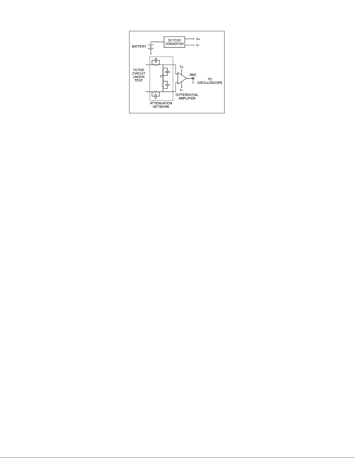
Figure 1
c. Making Measurements
Ensure the probe is fitted with four high-quality, AA cells. These should be cells that are
protected from leakage which could damage the power supply contacts in the probes.
Before making any measurements or connections refer to the safety information contained in
this document.
Connect the probe to one of the oscilloscope input channels ensuring the BNC connector is
fully mated, and the safety ground lead to the oscilloscope CAL BNC connection.
Page 4

Select the proper range setting on the probe using the slide-switch on the probe body.
Figure 2
Adjust the input coupling impedance and attenuation of the oscilloscope
channel to which the probe is connected using the input coupling menu as
shown in Figure 2.
Ensure 1 M input impedance ( ‘DC1M’ or ‘AC1M’ ) is selected. The
use of 50 input impedance will unduly load the output of the differential
probe resulting in reduced amplitude output and incorrect scaling.
To ensure the oscilloscope correctly interprets the vertical waveform scale
be sure to adjust the probe attenuation setting using the ‘Probe Atten’
menu controls. The example shown, x100 probe attenuation, would
achieve correct vertical scaling AP031 operating with a maximum range of
± 700 V ( see figure 3 below ).
Finally, adjust the vertical sensitivity and offset of the oscilloscope channel
to which the probe is connected to achieve an optimum display.
Figure 3
Probe Model Range Setting Probe Operating Range
( DC + Peak AC )
AP031 1/10 ± 70 V
1/100 ± 700 V
AP032 1/20 ± 140 V
1/200 ± 1400 V
Page 5

II. Specifications
GENERAL CHARACTERISTICS
Bandwidth
Rise Time
Attenuation
Atten. Accuracy
Input Resistance
Input Capacitance
Input Configuration
Input Voltage:
Max. Differential
Max. Common Mode ±700 V ( DC + peak AC )
Max. Absolute ±1400 V ( DC + peak AC ) or 1000 V r.m.s.
CMRR:
50 Hz - 86 dB - 80 dB
20 kHz - 66 dB - 60 dB
200 kHz - 56 dB - 50 dB
Output Offset (Typical )
Output Noise ( Typical )
AP031 AP032
25 MHz
14 ns
1:10 / 1:100 1:20 / 1 :200
±2 %
4 M
10 pF each side to ground
Differential
1:100 Range
±700 V ( DC + peak AC )
or 500 V r.m.s.
1:10 Range
±70 V ( DC + peak AC )
or 50Vrms
or 500 V r.m.s.
1.5 to 2 mV typical
±1400 V ( DC + peak AC )
±700 V ( DC + peak AC )
±1400 V ( DC + peak AC )
<±5 mV
1:200 Range
or 1000 V r.m.s.
1:20 Range
or 100Vrms
or 1000 V r.m.s.
Page 6

GENERAL CHARACTERISTICS
Ambient Temperature
Operating -10º C to 40º C
Storage -30º C to 70º C
Power requirement Four internal 1.5 V AA size batteries or 6 V d. c. / 60 mA
mains adaptor ( Not supplied )
Dimensions 6.6" ( 168 mm ) x 2.4" ( 62 mm ) x 0.79" ( 20 mm)
( excluding casing )
Cables BNC: 95 cm ( RG58 / U ), Input Lines: 45 cm ( PVC, double
insulation )
Accessories 2 x Safety Hooks, 4 mm compatible ( 1 red, 1 black )
Weight 9.35 oz ( 285 g ) excluding batteries and casing
Safety Certification IEC-1010, CAT III Approval
Page 7

III. Safety Information
International Electrical Symbols that appear
on the product:
Attention: Refer to this manual
before using the probe.
Danger, High Voltage.
The probe has been designed to comply with
IEC1010-1, IEC1010.2-031 Installation
Category ( Over-voltage Category ) III,
Pollution Degree 2. It is designed to be safe
under the following environmental
conditions:
Indoor use.
Altitude to 2000 m.
Temperature - 10 °C to 40 °C.
Maximum relative humidity 80 %
for temperatures up to 31 °C
decreasing linearly to 40 % relative
humidity at 50 °C.
OPERATOR SAFETY
The probe is designed to make differential
voltage measurements. It is not to be used
to insulate the circuit under test from the
measuring instrument.
When using the probe ensure that your
fingers are well clear from any exposed
connections and behind the safety hooks
shield. Use of other hooks than the provided
ones is not recommended.
In addition, the following guidelines should
be observed and followed:
MAXIMUM WORKING VOLTAGE
To avoid injury, do not use the probe above
where the potential between each input lead
and ground or the differential voltage
between the two input leads exceeds
1000 V r.m.s. ( 1400 V DC + peak AC ).
GROUNDING PRECAUTIONS
Ensure the BNC cable is connected to a
grounded oscilloscope before connecting the
measuring inputs.
Ensure the safety ground lead is always
connected to the oscilloscope CAL
connector.
Page 8

CLEANING
The exterior of the probe only should be
cleaned with a soft cloth moistened with
either water or isopropyl alcohol.
USAGE AND MAINTENANCE
The probe user should note that if the
equipment is used in a manner not specified
by the manufacturer, the protection provided
by the equipment may be impaired.
To guarantee accurate performance
characteristics, mechanical shocks should
be avoided, as well as damage to the cable
through excessive bending.
Do not use the probe if any part is damaged.
All maintenance should be referred to
qualified personnel.
LECROY SALES & SERVICE
Corporate Headquarters
700 Chestnut Ridge Road
Chestnut Ridge, NY 10977-6499
Tel: (914) 578 6020
Fax: (914) 578 5985
European Headquarters
Mannheimer Str. 175
D-69123 Heidelberg, Germany
Tel: 49 6221 82700
Fax: 49 6221 833827
European Manufacturi ng Headquarters
2, rue du Pré-de-la-Fontaine
1217 Meyrin 1 - Geneva, Switzerland
Tel: (022) 719 21 11
Fax: (022) 782 39 15
 Loading...