

Page 1
LeCroy
ADP300/305
Instruction Manual
February 2007
Page 2

Warranty
LeCroy warrants this oscilloscope accessory for normal use and operation within specification for
a period of one year from the date of shipment. Spare parts, replacement parts, and repairs are
warranted for 90 days.
In exercising its warranty, LeCroy, at its option, will either repair or replace any assembly returned
within its warranty period to the Customer Service Department or an authorized service center.
However, this will be done only if the product is determined by LeCroy’s examination to be
defective due to workmanship or materials, and the defect is not caused by misuse, neglect,
accident, abnormal conditions of operation, or damage resulting from attempted repair or
modifications by a non-authorized service facility.
The customer will be responsible for the transportation and insurance charges for the return of
products to the service facility. LeCroy will return all products under warranty with transportation
charges prepaid
This warranty replaces all other warranties, expressed or implied, including but not limited to any
implied warranty of merchantability, fitness, or adequacy for any particular purposes or use.
LeCroy shall not be liable for any special, incidental, or consequential damages, whether in
contract or otherwise.
Corporate Headquarters:
LeCroy Corporation
700 Chestnut Ridge Road
Chestnut Ridge, NY 10977-6499
Tel: (845) 578-6020, Fax: (845) 578-5985
Internet: www.lecroy.com
Copyright 2007 by LeCroy Corporation. All rights reserved.
LeCroy, ActiveDSO, JitterTrack, WavePro, WaveMaster, WaveSurfer, WaveLink, WaveExpert,
WaveJet, and Waverunner are registered trademarks of LeCroy Corporation. Other product or
brand names are trademarks or requested trademarks of their respective holders. Information in
this publication supersedes all earlier versions. Specifications subject to change without notice
ADP30X-OM-E Rev B
914814-00 Rev A
ii ADP30X-OM-E Rev B
Page 3
Manufactured under an ISO 9000
Registered Quality Management System
Visit www.lecroy.com to view the
certificate.
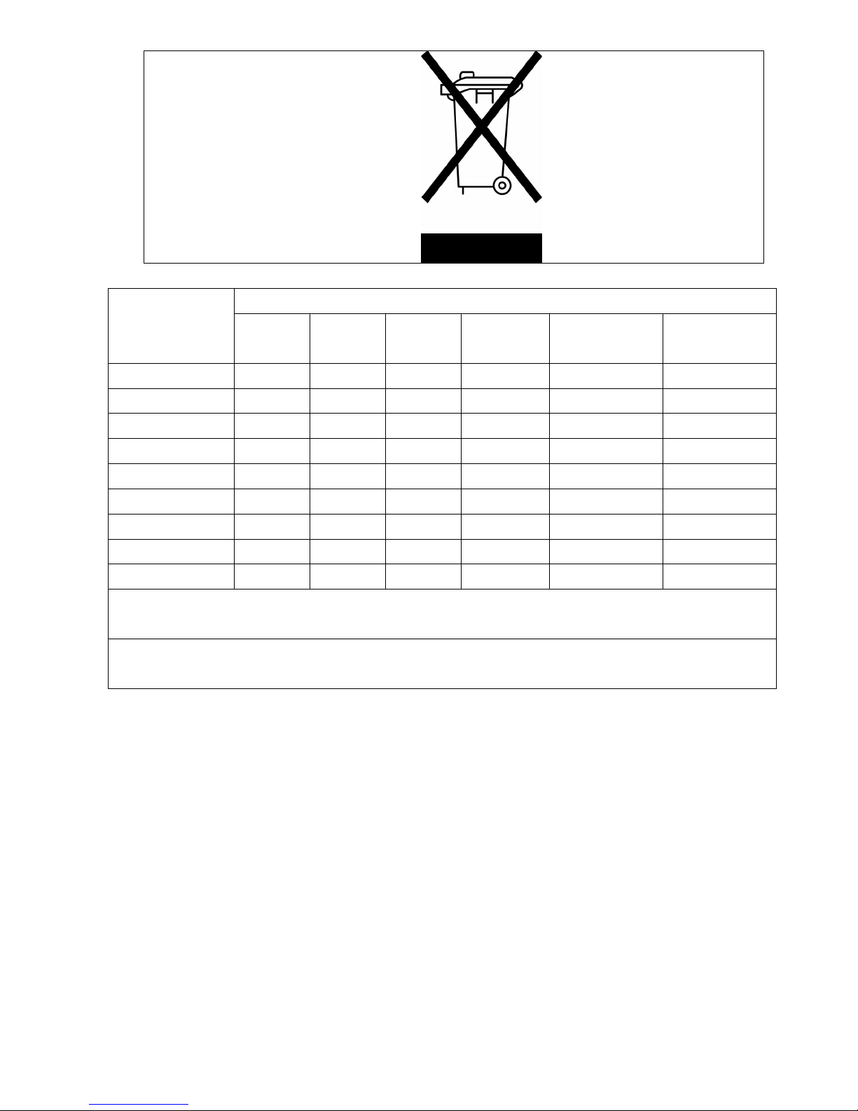
This electronic product is subject to
disposal and recycling regulations
that vary by country and region.
Many countries prohibit the
disposal of waste electronic
equipment in standard waste
receptacles.
For more information about proper
disposal and recycling of your
LeCroy product, please visit
www.lecroy.com/recycle.
有毒有害物质和元素
部件名称
铅
(Pb)
汞
(Hg)
镉
(Cd)
六价铬
6+
(Cr
)
多溴联苯
(PBB)
多溴二苯醚
(PBDE)
PCBAs X O X X X X
机械硬件 O O X O O O
金属片 O O X O O O
塑料部件 O O O O X X
保护外壳 O O O O X X
电缆组件 X O X O X X
探头端部 X O X O X X
O: 表明该有毒有害物质在该部件所有均质材料中的含量均在SJ/T11363-2006标准规定的限量要求之下。
X: 表明该有毒有害物质至少在该部件的某一均质材料中的含量均在SJ/T11363-2006标准规定的限量要求。
EFUP (对环境友好的使用时间) 使用条件:参阅本手册“ 规范” 部分规定的环境条件。
ADP30X-OM-E Rev B iii
Page 4

Lead
Part Name
PCBAs X O X X X X
Mechanical
Hardware
Sheet Metal O O X O O O
Plastic Parts O O O O X X
Protective Case O O O O X X
Cable Assemblies X O X O X X
Probe Tips X O X O X X
O: Indicates that this toxic or hazardous substance contained in all of the homogeneous materials for
this part is below the limit requirement specified in SJ/T11363-2006.
X: Indicates that this toxic or hazardous substance contained in at least one of the homogenous
materials used for this part is above the limit requirement specified in SJ/T11363-2006.
(Pb)
Mercury
O O X O O O
Toxic or Hazardous Substances and Elements
(Hg)
Cadmium
(Cd)
Hexavalent
Chromium
6+
(Cr
Polybrominate
d Biphenyls
)
(PBB)
Polybrominated
Diphenyl
Ethers (PBDE)
EFUP (Environmental Friendly Use Period) Use Conditions: refer to the environmental conditions
stated in the specifications section of this Manual.
iv ADP30X-OM-E Rev B
Page 5
ADP30X-OM-E Rev B v
Page 6

BLANK PAGE
vi ADP30X-OM-E Rev B
Page 7

ADP30X Operator’s Manual
OVERVIEW...........................................................................................................3
Description .......................................................................................................................................3
Key Benefits ..................................................................................................................................... 3
Conventions Used in this Manual ....................................................................................................4
Standard Accessories.......................................................................................................................5
Description of Accessories............................................................................................................... 5
SAFETY INFORMATION......................................................................................8
OPERATION.......................................................................................................10
Connecting the Probe to the Test Instrument................................................................................. 10
Connecting the Probe to the Test Circuit .......................................................................................10
Operation with a LeCroy Oscilloscope...........................................................................................10
Smart Offset ................................................................................................................................... 11
Bandwidth Limit (ADP305 only) ..................................................................................................... 11
Auto Zero........................................................................................................................................ 11
REMOTE CONTROL COMMANDS....................................................................12
Introduction ....................................................................................................................................12
Command List ................................................................................................................................12
Probe Auto Zero ............................................................................................................................. 13
Probe Bandwidth Limit ...................................................................................................................14
Probe Coupling ..............................................................................................................................15
Probe Offset ................................................................................................................................... 16
Probe Volts/div ...............................................................................................................................17
REFERENCE INFORMATION............................................................................18
Differential Mode and Common Mode ........................................................................................... 18
Differential Mode Range and Common Mode Range....................................................................18
Common Mode Rejection Ratio .....................................................................................................18
CARE AND MAINTENANCE..............................................................................20
Cleaning ......................................................................................................................................... 20
Calibration Interval .........................................................................................................................20
Service Strategy.............................................................................................................................20
Troubleshooting..............................................................................................................................20
Returning a Defective Probe..........................................................................................................20
Replacement Parts.........................................................................................................................21
FUNCTIONAL TEST...........................................................................................23
Test Equipment Required...............................................................................................................23
Test procedure ...............................................................................................................................23
PERFORMANCE VERIFICATION ......................................................................24
Test Equipment Required...............................................................................................................24
ADP30X-OM-E Rev B 1
Page 8

ADP300/305 Probe
Preliminary Procedure....................................................................................................................24
Procedure....................................................................................................................................... 25
SPECIFICATIONS..............................................................................................27
Nominal Characteristics .................................................................................................................27
Warranted Characteristics.............................................................................................................. 27
Typical Characteristics ................................................................................................................... 28
Environmental Characteristics .......................................................................................................28
Physical Characteristics ................................................................................................................. 28
Compliance and Certifications .......................................................................................................29
APPENDIX A ...................................................................................................... 31
Performance Verification Test record .............................................................................................31
ADP300/ADP305 Test Record .......................................................................................................32
APPENDIX B ...................................................................................................... 33
SAC-01 Mounting Instructions .......................................................................................................33
2 ADP30X-OM-E Rev B
Page 9

ADP30X Operator’s Manual
OVERVIEW
Description
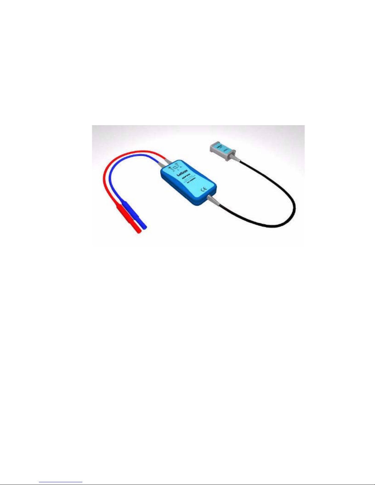
The ADP30X family of high voltage active differential probes is safe, easy-to-use, and ideally
suited for power measurements.
The 20 MHz ADP300 is perfect for troubleshooting low frequency power circuits, and other
circuits where the reference potential is elevated from ground or the location of ground is
unknown.
The 100 MHz ADP305 is designed for measuring high-speed floating voltages found in today’s
power electronics, like switching power supplies.
With the ProBus interface, the ADP30X becomes an integral part of the oscilloscope. For the
ADP305, the attenuation, offset, and bandwidth limit are all controlled from the oscilloscope’s
front panel or by means of remote control commands. This means that the complete
measurement setup can be saved and recalled by the oscilloscope and all measurement values
will be correct. The oscilloscope provides power to the probe, so there is no need to worry about
a separate power supply or changing batteries.
The sensitivity of the ADP300 ranges from 1 V/div to 350 V/div; and the sensitivity for the
ADP305 ranges from 200 mV/div to 350 V/div.
Attenuation is automatically selected by the oscilloscope to either ÷100 or ÷1000.
Key Benefits
• True Differential Measurements
• EN 61010 1000 V CAT III Safety Compliance
• ProBus Interface with Automatic Scaling
• Auto-Zeroing
ADP30X-OM-E Rev B 3
Page 10
ADP300/305 Probe
Conventions Used in this Manual
The following conventions may appear in this manual:
Note
A Note contains information relating to the use of the product.
CAUTION
A Caution contains information that should be followed to avoid
possible damage to the instrument or the device under test.
WARNING
A Warning alerts you to a potential hazard. Failure to adhere to
the statement in a WARNING message could result in personal
injury.
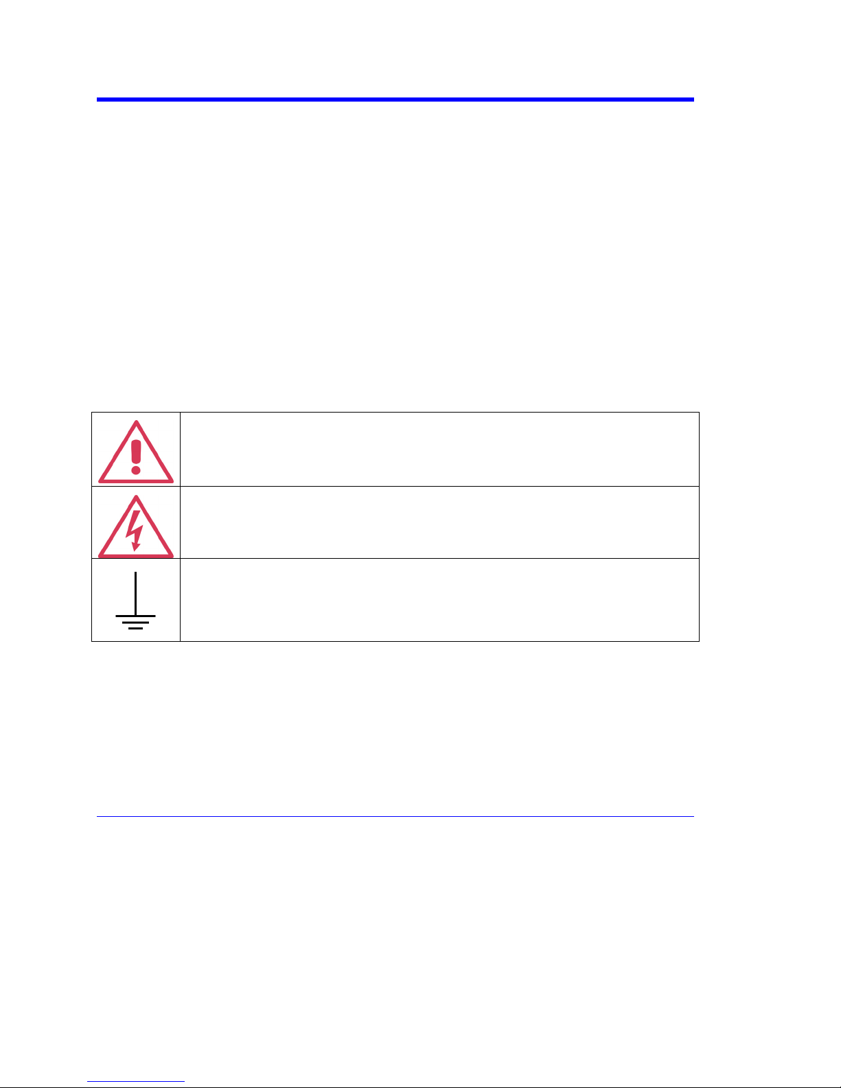
The following symbols may appear on the product:
This refers you to additional information contained in this manual. The
corresponding information in the manual is similarly denoted. This is a reminder
that high voltage may be present and that appropriate caution should be taken.
This is a reminder that high voltage may be present and that appropriate caution
should be taken.
Earth (ground) Terminal
4 ADP30X-OM-E Rev B
Page 11

Standard Accessories
Description of Accessories
ADP30X Operator’s Manual
ADP300 ADP305
Instruction Manual x x
Certification of Compliance x x
Hook and Loop Strap for holding probe x x
Plunger Hook Tip x x
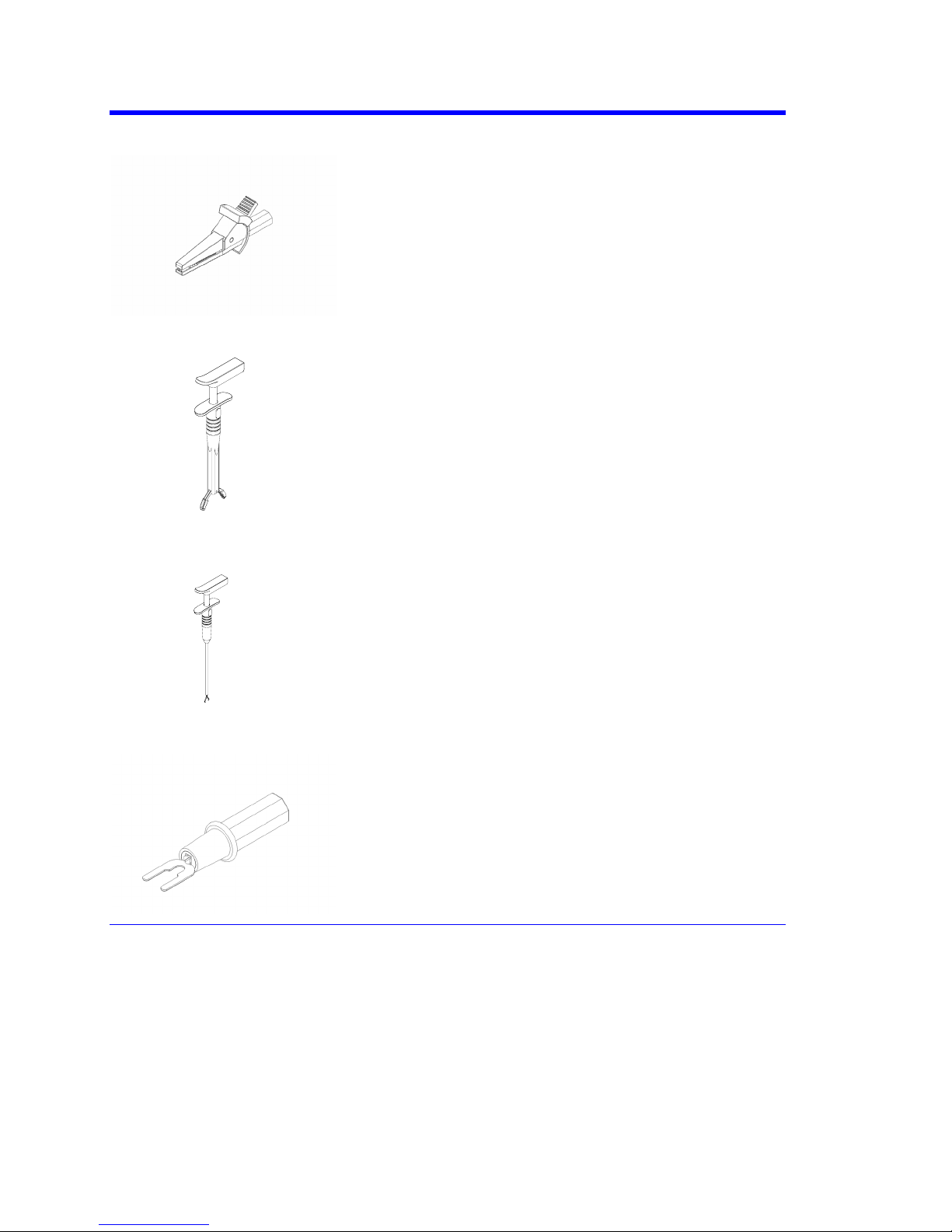
Safety Alligator Clip x
Plunger Jaw Clip x
Plunger Clamp Clip x
Spade Terminal x
Soft Accessory Case x
WARNING
For electric shock protection, only attachment accessories rated
for 1000 V Installation Category III, per EN 61010-1:1993 should
be used with this product
Plunger Hook Clip (1 Red, 1 Blue)
Insulated, 1000 V, CAT III. Designed to attach to wire leaded
parts, the overall length is 117 mm (4.60 inches), and the hook
extends 10 mm (0.41 inch) when the plunger is fully pressed.
ADP30X-OM-E Rev B 5
Page 12
ADP300/305 Probe
Safety Alligator Clip (1 Red, 1 Blue)
Insulated, 1000 V, CAT III. Designed to attach to large
components, such as busbars and large bolts, the overall
length is 90 mm (3.5 inches) and the jaw opens to 22 mm
(0.87 inch) max.
Plunger Jaw Clip (1 Red, 1 Blue)
Insulated, 1000 V, CAT III. The clip is designed to securely
grasp thick wires, cables, ground leads, rails, and even screw
heads. The overall length is 134 mm (5.26 inches). The steel
jaw extends 12 mm (0.48 inch) and opens to 25 mm (1 inch).
Plunger Clamp Clip (1 Red, 1 Blue)
Insulated, 1000 V, CAT III. Designed for attaching to hard-toreach test points, the entire body is fully insulated. The overall
length is 190 mm (7.5 inch). The clamp can grab leads, pins
and wires up to 5 mm (0.2 inch) in diameter.
Spade Terminal
Insulated, 1000 V, CAT III. Designed to connect to terminal
strips, posts, and screws, the overall length is 63 mm (2.48
inch).
6 ADP30X-OM-E Rev B
Page 13

ADP30X Operator’s Manual
Soft Accessory Case
This can be used to carry probes and accessories. It can also be mounted on your oscilloscope
for storing all your accessories and manuals. See Appendix B for installation instructions.
ADP30X-OM-E Rev B 7
Page 14

ADP300/305 Probe
SAFETY INFORMATION
To avoid personal injury and to prevent damage to the probe or any products connected to it,
review the following safety precautions. To avoid potential hazards, use the probe only as
specified.
Warning
To avoid fire or personal injury, comply with the following:
For indoor use only.
The probe is intended to be used only with measurement
instruments that are connected to earth ground through the input
BNC connector.
Connect the probe to the measurement instrument before
connecting the test leads to a voltage source.
Do not disconnect the probe from the instrument while the test
leads are connected to a voltage source.
Use of the probe (or the oscilloscope it is connected to) in a
manner other than that specified may impair the protection
mechanisms.
Observe all terminal ratings. Do not apply a potential to any input
that exceeds the maximum rating of that input. See chapter 9 for
detailed specifications of the probe.
To avoid RF burns, do not handle the probe while the input leads
are connected to potentials above the RF Burn Limits shown on
the derating curve (see “Specifications”).
When measuring signals above 2 MHz, be sure to comply with
the voltage vs. frequency derating curve (see “Specifications”).
Otherwise the probe may overheat, thereby compromising the
insulation system.
Avoid exposed circuitry. Do not touch exposed connections and
components when power is on.
Do not use in wet or explosive atmospheres. Remove any
contamination from the probe housing before connecting the
8 ADP30X-OM-E Rev B
Page 15

ADP30X Operator’s Manual
probe inputs to any circuits. Be sure that the surface of the probe
is completely dry before connecting the inputs.
Do not use the probe if any part is damaged. All maintenance
should be referred to qualified service personnel.
Any test lead or accessory provided by the user must comply
with EN 61010-1 Installation Category III, 1000 V rating.
Do not operate with suspected failures. If you suspect there is
damage to the probe, have it inspected by qualified service
personnel.
Use only LeCroy supplied accessories, or order replaceable
parts listed in the Replacement Parts list.
ADP30X-OM-E Rev B 9
Page 16

ADP300/305 Probe
OPERATION
Connecting the Probe to the Test Instrument
The ADP30X series of probes has been designed for use with LeCroy oscilloscopes equipped
with the ProBus interface. When you attach the probe output connector to the scope’s input
connector, the scope will recognize the probe, set the scope input termination to 1 MΩ, and
activate the probe control functions in the user interface.
Connecting the Probe to the Test Circuit
The ADP30X series of probes is ideally suited for applications where no ground is available or
where the location of a ground connection is unknown.
Two inputs are available at the probe tip to connect the probe to a circuit under test. For accurate
measurements, the + and – inputs both must always be connected to the test circuit. Positive
voltages applied to the + input (red) relative to the – input (blue) will deflect the oscilloscope trace
toward the top of the screen.
To maintain the high performance capability of the probe in measurement applications, care must
be exercised in connecting the probe to the test circuit. Increasing the parasitic capacitance or
inductance in the input paths may introduce a “ring” or may slow the rise time of fast signals.
Input leads that form a large loop area will pick up any radiated electromagnetic field that passes
through the loop and may induce noise into the probe inputs. Because this signal will appear as a
differential mode signal, the probe’s common mode rejection will not remove it. This effect can be
greatly reduced by twisting the input leads together to minimize the loop area.
High common mode rejection requires precise matching of the relative gain or attenuation in the +
and – input signal paths. Mismatches in additional parasitic capacitance, inductance, delay, and a
source impedance difference between the + and – signals will lower the common mode rejection
ratio. Therefore, it is desirable to use the same length and type of wire and connectors for both
input connections. When possible, try to connect the inputs to points in the circuit with
approximately the same source impedance.
Operation with a LeCroy Oscilloscope
When the ADP30X is connected to a LeCroy oscilloscope, the displayed scale factor and
measurement values will be adjusted to account for the effective gain of the probe.
Through the oscilloscope software, the probe’s internal attenuation and offset can be
conveniently controlled through the oscilloscope’s user interface.
Turning the V
attenuation to give full available dynamic range from 1 V/div to 350 V/div for the ADP300, and
from 200 mV/div to 350 V/div for the ADP305. Some of the transition of the scale factor will result
in a change of attenuation.
OLTS/DIV knob will control the oscilloscope’s scale factor and the probe’s internal
10 ADP30X-OM-E Rev B
Page 17

ADP30X Operator’s Manual
Smart Offset
The ADP30X has offset capability. This allows you to remove a DC bias voltage from the
differential input signal while maintaining DC coupling.
The offset range of the probe is a function of the oscilloscope’s sensitivity and the probe’s
attenuation. This ensures that the probe will never be overdriven on screen. In addition, it will
prevent the oscilloscope from being overdriven and getting inaccurate measurements.
Bandwidth Limit (ADP305 only)
To comply with various test standards used for quantifying output noise of power supplies, the
ADP305 is capable of switching the bandwidth limit from Off (maximum bandwidth) to 20 MHz in
the channel Vertical Adjust dialog.
Auto Zero
The ADP30X incorporates an Auto Zero function to remove the DC offset from the Differential
Amplifier’s output. Auto Zero must be invoked by the user. You may do this even while the probe
is connected to a live circuit.
After several minutes of warm-up, or when the probe is exposed to a large shift in ambient
temperature, some DC offset drift may occur from thermal effects in the amplifier. To initiate an
Auto Zero cycle, select "AUTO ZERO" in the oscilloscope’s user interface. During an Auto Zero
cycle the oscilloscope will automatically disconnect the ADP30X inputs from the circuit under test,
perform the auto zero function, and reconnect the inputs.
ADP30X-OM-E Rev B 11
Page 18

ADP300/305 Probe
REMOTE CONTROL COMMANDS
Introduction
When attached to a LeCroy oscilloscope equipped with ProBus interface, the ADP30X Active
Differential Probe can be remotely controlled, along with the other oscilloscope functions. The
control interface can be either the RS-232 or IEE-488 (GPIB) buses. The commands that control
the probe are described below. The text for the command description is formatted in a style
consistent with the oscilloscope command description contained in the LeCroy Digital
Oscilloscopes Remote Control Manual supplied with the oscilloscope. Please refer to this manual
for additional information on the remote control buses and the conventions used in the command
descriptions.
The commands begin with the "PRx:" prefix, where "x" is the channel that the ADP30X is
connected to. These commands are similar to the channel commands that use the prefix "Cx:".
The difference is that the "PRx:" form refers to the probe tip, whereas the "Cx:" form refers to the
oscilloscope input connector. For example, "PRx:VDIV" sets the Volts per division at the probe
tip, while "Cx:VDIV" sets the Volts per division at the BNC input connector, without factoring the
gain or attenuation factor of ADP30X probe. The "PRx:" form of these commands are only active
when the ADP30X probe is connected to the selected channel. An error will result when an
ADP30X specific command is sent to the oscilloscope without a differential probe connected to
the selected channel.
Command List
PRx:AUTOZERO Initiates an auto zero cycle in the probe.
PRx:BWL Selects the probe upper bandwidth limit.
PRx:COUPLING Selects the input coupling of the probe.
PRx:OFFSET Selects the probe offset voltage.
PRx:VDIV Selects the vertical scale factor of the probe/oscilloscope system.
12 ADP30X-OM-E Rev B
Page 19

ADP30X Operator’s Manual
Probe Auto Zero
PRx:AUTOZERO, PRx:AZ
Command
Description The PRx:AUTOZERO command initiates an auto zero cycle in the
ADP30X probe to remove any offset drift.
The probe input can remain connected to the test circuit during the auto
zero cycle.
Command Syntax <channel>:AutoZero
<channel>:= {PR1, PR2, PR3, PR4}
Example The following command initiates an auto zero in the ADP30X
Differential Probe attached to channel 1:
CMD$="PR1:AZ":CALL IBWRT(SCOPE%,CMD$)
ADP30X-OM-E Rev B 13
Page 20

ADP300/305 Probe
Probe Bandwidth Limit
PRx:BANDWIDTH_LIMIT, PRx:BWL
Command/Query
Description The PRx:BANDWIDTH_LIMIT command sets the upper (HF) –3 dB
bandwidth limit of the ADP305 probe. The arguments are in Hertz.
Note
The PRx:Bandwidth_Limit command is not available with
model ADP300 .
The PRx:Bandwidth_Limit query returns the upper bandwidth limit
setting for the differential probe connected to the specified channel.
Command Syntax <channel>:BWL<upper bandwidth>
<channel>:={PR1, PR2, PR3, PR4}
<upper bandwidth>:={OFF, 20M}
Query Syntax <channel>:BWL?
Response Format <channel>:BWL <upper bandwidth>
Example The following command sets the upper bandwidth of the ADP305
connected to channel 1 to 20 MHz.
CMD$="PR1:BWL 20M": CALL IBWRT(SCOPE%,CMD$)
14 ADP30X-OM-E Rev B
Page 21

ADP30X Operator’s Manual
Probe Coupling
PRx:COUPLING, PRx:CPL
Command/query
Description The PRx:COUPLING command selects the coupling mode of the
ADP30X probe.
The PRx:COUPLING? query returns the coupling mode of the selected
channel.
Command Syntax <channel>:CouPLing<coupling>
<channel>:={PR1, PR2, PR3, PR4}
<coupling>:={DC, GND}
Query Syntax <channel>:CouPLing?
Response Format <channel>:CPL <coupling>
Example The following command sets the coupling to DC in the ADP30X
differential probe connected to channel 2.
CMD$=:PR2:CPL DC": CALL IBWRT(SCOPE%,CMD$)
ADP30X-OM-E Rev B 15
Page 22

ADP300/305 Probe
Probe Offset
PRx:OFFSET, PRx:OFST
Command/Query
Description When an ADP30X probe is connected to a channel, the OFFSET
command sets the probe offset value.
The maximum range and resolution is determined by the V/DIV setting. If
an out-of-range value is entered, the differential probe will set the offset
to the closest valid value, and the VAB bit (bit 2) in the STB register will
be set.
The OFFSET? query returns the offset voltage of the differential probe
connected to the specified channel.
Command Syntax <channel>: OFfSeT<offset>
<channel>:={PR1, PR2, PR3, PR4}
ADP305: <offset> ={-40V to +40V} for 200 mV/div to 499 mV/div
(LC series) or
={-100V to +100V} for 200 mV/div to 499 mV/div (LT series) or
={-100V to +100V} for 500 mV/div to 9.9 V/div or
={-1000V to +1000V} for 10V/div to 99 V/div or
={-(1400V-4(V/Div setting)) to (1400V-
4(V/Div setting))} for 100 V/div to 350 V/div
ADP300: <offset> ={-100V to +100V} for 1 V/div to 9.9 V/div or
={-1000V to +1000V} for 10 V/div to 99 V/div or
={-(1400V-4(V/Div setting)) to (1400V- 4(V/Div
setting))} for 100 V/div to 350 V/div
Note: The suffix V is optional
Query Syntax <channel>:OFfSeT?
Response Format <channel>:OFST <offset>
Example The following command sets the offset at the probe tip of the ADP30X
differential probe connected to 1 to 5 volts:
CMD$="PR1:OFST 5": CALL IBWRT(SCOPE%,CMD$)
16 ADP30X-OM-E Rev B
Page 23

ADP30X Operator’s Manual
Probe Volts/div
PRx:VOLT_DIV,PRx:VDIV
Command/Query
Description The PRx:VOLT_DIV command sets the vertical sensitivity at the
ADP30X input. The effective gain of the differential probe is factored into
the vertical sensitivity.
The valid range of arguments is fixed by the probe type. If an out-of-
range value is entered, the oscilloscope will set the vertical sensitivity to
the closest value and set the VAB bit (bit 2) in the STB register.
The PRx:VOLT_DIV? query returns the vertical sensitivity at the probe
input of the specified channel.
Command Syntax <channel>:Volt_DIV <sensitivity>
<channel>:={PR1, PR2, PR3, PR4}
<sensitivity>:={200 mV to 350 V} for the ADP350
<sensitivity>:={1 V to 350 V} for the ADP300
Note: The suffix V is optional
Query Syntax <channel>:Volt_DIV?
Response Format <channel>:VDIV <sensitivity>
Example The following command sets the vertical sensitivity at the probe tip of the
ADP30X probe connected to channel 3 to 2 Volts/div:
CMD$="PR3:VDIV 2":CALL IBWRT(SCOPE%,CMD$)
ADP30X-OM-E Rev B 17
Page 24

ADP300/305 Probe
REFERENCE INFORMATION
Differential Mode and Common Mode
Differential amplifiers amplify the voltage difference that appears between the + input and – input.
This voltage is referred to as the Differential Mode or Normal Mode voltage. The voltage
component that is referenced to earth and is identical on both inputs is rejected by the amplifier.
This voltage is referred to as the Common Mode voltage and can be expressed as:
VV
+
InputInput
V
=
CM
Differential Mode Range and Common Mode Range
Differential Mode range is the maximum signal that can be applied between the + and – inputs
without overloading the amplifier, which otherwise would result in clipping or distorting the
waveform measured by the oscilloscope.
The Common Mode Range is the maximum voltage with respect to earth ground that can be
applied to either input. Exceeding the common mode range can result in unpredictable
measurements. Because the Common Mode signal is normally rejected and not displayed on the
oscilloscope, you need to be careful to avoid accidentally exceeding the common mode range.
Common Mode Rejection Ratio
−+
2
The ideal differential amplifier would amplify only the differential mode voltage component and
reject all of the common mode voltage component. Real differential amplifiers are not perfect, so
a small portion of the common mode voltage component appears at the output. Common Mode
Rejection Ratio (CMRR) is the measure of how well the amplifier rejects the common mode
voltage component. CMRR is equal to the differential mode gain (or normal gain) divided by the
common mode gain. The common mode gain is equal to the output voltage divided by the input
voltage when both inputs are driven by only the common mode signal. CMRR can be expressed
as a ratio (e.g., 10
rejection the better the performance.
The first order term that determines the CMRR is the relative gain matching between the + and –
input paths. To obtain high CMRR values, the input attenuators in a differential amplifier are
precisely matched to each other. This matching includes the DC attenuation as well as the
capacitance that determines the AC attenuation. As the frequency of the common mode
component increases, the effects of stray parasitic capacitance and inductance in determining the
AC component becomes more pronounced. The CMRR becomes smaller as the frequency
increases. Hence, the CMRR is usually specified in a graph of CMRR versus common mode
frequency.
000:1) or implicitly in dB (e.g., 80 dB). The higher the number the greater the
18 ADP30X-OM-E Rev B
Page 25

ADP30X Operator’s Manual
The common mode frequency in these graphs is assumed to be sinusoidal. In real life
applications, the common mode signal is seldom a pure sine wave. Signals with pulse wave
shapes contain frequency components much higher than the repetition rate may suggest. As
such, it is very difficult to predict actual performance in the application for CMRR versus
frequency graphs. The practical application of these graphs is to compare the relative common
mode rejection performance between different amplifiers.
ADP30X-OM-E Rev B 19
Page 26

ADP300/305 Probe
CARE AND MAINTENANCE
Cleaning
The exterior of the probe and cable should be cleaned using only a soft cloth lightly moistened
with water or isopropyl alcohol. The use of abrasive agents, strong detergents, or other solvents
may damage the probe. Always ensure that the input leads are free of debris.
Note
The probe case is not sealed and should never be immersed in
any fluid.
Calibration Interval
This probe has no adjustments. The recommended calibration interval is one year. (A
Performance Verification Procedure is included in this manual.)
Service Strategy
The ADP30X series probes utilize fine-pitch surface mount devices. It is, therefore, impractical to
attempt repair in the field. Defective probes must be returned to a LeCroy service facility for
diagnosis and exchange. A defective probe under warranty will be replaced with a factory
refurbished probe. A probe that is not under warranty can be exchanged for a factory refurbished
probe for a modest fee. You must return the defective probe in order to receive credit for the
probe core.
Troubleshooting
If the probe is not operating properly the problem may be the way in which it is used. Before
assuming that the probe is defective, perform the following troubleshooting procedures:
1. For LeCroy LT and LC series scopes, verify that the firmware version is 8.5 or higher.
2. Waveform is inverted. — Make sure that the + lead (Red) is connected to the proper test
point.
3. No DC. — Make sure that the attachment accessory is completely plugged onto the lead.
4. No output signal. — Make sure that DC coupling is selected.
Returning a Defective Probe
The procedure for returning a defective probe is as follows:
Contact your local LeCroy sales representative to find out where to return the product. All
returned products should be identified by model number and serial number. Provide your name
and contact number and, if possible, describe the defect or failure. In case of products returned to
20 ADP30X-OM-E Rev B
Page 27

ADP30X Operator’s Manual
the factory, a Return Authorization Number (RAN) should be used. The RAN can be obtained
from your nearest LeCroy office or the New York Customer Care Center.
Return shipment should be made prepaid. LeCroy cannot accept COD or Collect Return
shipments. We recommend shipping by air freight. It is important that the RAN be clearly shown
on the outside of the shipping package for prompt forwarding to the appropriate department.
1. Contact your local LeCroy sales or service representative to obtain a Return
Authorization Number.
2. Remove all accessories from the probe. Do not include the manual.
3. Pack the probe in its case. Surround the probe with its original packing material (or
equivalent) and box.
4. Label the case with a tag containing
• The RAN
• Name and address of the owner
• Probe model and serial number
• Description of failure
5. Pack the probe case in a cardboard shipping box with adequate padding to avoid
damage in transit.
6. Mark the outside of the box with the shipping address given to you by the LeCroy
representative; be sure to add the following:
• ATTN: <RAN assigned by the LeCroy representative>
• FRAGILE
7. Insure the item for the replacement cost of the probe.
8. Ship the package to the appropriate address.
Replacement Parts
The probe connection accessories and other common parts can be ordered through the regional
customer care centers. Refer to the list below for LeCroy part numbers. Defective probes can be
replaced on an exchange basis. Replacement probes are factory repaired, inspected, and
calibrated to the same standards as a new product. In order to obtain a replacement probe, you
must return the defective probe. The returned probe should be sent back to the regional customer
care center without any accessories, manual, or case.
ADP30X-OM-E Rev B 21
Page 28

ADP300/305 Probe
Item LeCroy P/N Alternate P/N
ADP300 Exchange Unit APD300-PROBE-FRU
ADP305 Exchange Unit APD305-PROBE-FRU
Instruction Manual ADP30X-OM-E
Soft Carrying Case SAC-01
Plunger Hook Clips PK30X-1
Safety Alligator Clips PK30X-2
Plunger Jaw Clips PK30X-3
Plunger Clamp Clips PK30X-4
Safety Spade Terminals PK30X-5
Supplier of alternate accessories:
Mueller Electric Co.
1583 East 31st Street
Cleveland, OH 44114
Phone: 216-771-5225 or 800-955-2629
Fax: 216-771-3068
www.muellerelectric.com
Mueller: BU-20431-2 (Red)
Mueller: BU-20431-6 (Blue)
Mueller: BU-656-2 (Red)
Mueller: BU-656-6 (Blue)
Mueller: BU-20434-2 (Red)
Mueller: BU-20434-6 (Blue)
Mueller: BU-20433-2 (Red)
Mueller: BU-20433-6 (Blue)
Mueller: BU-30214-2 (Red)
Mueller: BU-30214-6 (Blue)
22 ADP30X-OM-E Rev B
Page 29

ADP30X Operator’s Manual
FUNCTIONAL TEST
This procedure should be performed to confirm the basic operation of the probe, or to aid in
determining the source of a problem, rather than to verify the accuracy of the probe. You can
perform the Functional Test without removing the probe covers.
Test Equipment Required
Other than a LeCroy oscilloscope, no special test equipment is required for the functional test.
Test procedure
1. Connect the ADP300 or ADP305 to any vertical channel on the oscilloscope.
2. Select the channel to which the probe is connected.
3. Press the A
4. If necessary, adjust the O
UTO ZERO button in the user interface menu.
FFSET to 0.000 V.
5. Using accessory clips, attach the Red clip to the + CAL out and the Blue clip to the
ground post of the CAL out signal. For oscilloscopes with the CAL signal on a BNC
connector, a BNC-to-Banana adapter (e.g., Pomona model 1296) may be used.
6. Press A
UTOSETUP.
7. Set the sensitivity of the probe to 1 V/div.
8. Set the CAL output to 1 V
9. Verify that the displayed square wave is 1 V
square wave.
p-p
centered at +0.5 V.
p-p
10. Reverse the accessory leads on CAL out and verify that the displayed square wave is still
1 V, but is now centered at
–0.5 V.
11. Change the COUPLING on the user interface menu to Grounded to verify that the signal
disappears and that the trace is still centered on the screen.
12. Verify that the probe attenuation shows X100.
13. Set the V
OLTS/DIV to 100 V.
14. Verify that the probe attenuation now shows X1K.
ADP30X-OM-E Rev B 23
Page 30

ADP300/305 Probe
PERFORMANCE VERIFICATION
This procedure can be used to verify the warranted characteristics of the ADP30X series Active
Differential Probes.
If the product does not meet specifications, it should be returned to a LeCroy service center.
There are no user accessible adjustments, so there is no adjustment procedure.
Test Equipment Required
The following table lists the test equipment and accessories (or their equivalents) that are
required for performance verification of the ADP30X Active Differential probe.
This procedure is designed to minimize the number of calibrated test instruments required.
Description Minimum Requirements Test Equipment Examples
Digital Multimeter
Function Generator Sine Wave output waveforms
BNC Coaxial Cable
Calibration Fixture ProBus Extender Cable LeCroy PROBUS-CF01
Banana Plug Adapter Female BNC-to-Dual Banana
Insulated Banana Plug
Insulated Banana Couplers (2)
DC: 0.1% Accuracy
AC: 0.2% accuracy to measure
700 mV at 70 Hz
20 V
p-p
Male-to-Male 50 Ω Cable
Plug
Insulated BNC-to-Shrouded
Banana Plug
Agilent Technologies 34401A or
Fluke 8842A-09 or
Keithley 2001
Agilent Technologies 33120A or
Stanford Research Model DS340
or
Leader LAG-120B
Pomona 5697-36
Pomona 1269 or
Mueller BU-00260
Mueller BU-5671-B-12-0
Mueller BU-32601-2 (Red)
Mueller BU-32601-6 (Blue)
Only the parameters listed in boldface in the "Minimum requirements" column must be calibrated
to the accuracy indicated.
Because the input and output connector types may vary on different brands and models of test
instruments, additional adapters or cables may be required.
Preliminary Procedure
1. Connect the ADP30X under test to the female end of the ProBus Extension Cable.
Connect the male end of the ProBus Extension Cable to any channel of the oscilloscope.
2. Turn the oscilloscope on and allow at least 30 minutes warm-up time before performing
the Certification Procedure.
24 ADP30X-OM-E Rev B
Page 31

ADP30X Operator’s Manual
3. Turn on the other test equipment and allow these to warm up for the time recommended
by the manufacturer.
4. While the instruments are reaching operating temperature, make a photocopy of the
Performance Verification Test Record (located in Appendix A), and fill in the necessary
data.
Procedure
1. Set the function generator to sine wave, 70 Hz, and an output voltage of approximately
7.00 V rms (into a high impedance output).
2. Set the DMM to measure AC Volts.
3. Connect the function generator output to the DMM, using a BNC cable and a female BNC
to dual banana plug adapter.
4. Adjust the function generator output voltage until the DMM reads 7.000 V ±0.01 V.
5. Record the DMM reading to 1 mV resolution in the Test Record.
6. Disconnect the BNC cable from the function generator and from the BNC-to-banana plug
adapter on the DMM. (Leave the banana plug adapter connected to the DMM).
7. Connect the BNC connector from the probe under test to the BNC-to-banana plug
adapter on the DMM.
8. Connect the insulated banana plug adapter to the function generator.
9. Using the insulated banana couplers, connect the positive lead (Red) of the probe under
test to the positive output of the BNC-to-banana plug adapter and the negative lead
(Blue) to the negative or return output.
10. Set the oscilloscope scale factor to 20 V/div.
11. Record the DMM reading to 0.01 mV resolution in the Test Record.
12. Multiply the measured output voltage recorded in step 11 by 1000 and divide this number
by the function generator output voltage (probe input voltage) recorded in step 5.
Subtract 1 from this number and multiply the result by 100 to get the error in percent:
⎛
1000
Error
% x
13. Record the answer to two significant places (±x.xx%) on line 13 in the Test Record.
14. Verify that the error ≤ 1.00%.
15. Decrease the oscilloscope scale factor to 5 V/div.
16. Record the DMM reading to 0.01 mV resolution in the Test Record.
ADP30X-OM-E Rev B 25
⎜
⎜
⎝
geInputVolta
⎞
geutputVoltaxMeasuredO
⎟
−=
1001
⎟
⎠
Page 32

ADP300/305 Probe
17. Multiply the measured output voltage recorded in step 16 by 100 and divide this number
by the function generator output voltage (probe input voltage) recorded in step 5.
Subtract 1 from this number and multiply the result by 100 to get the error in percent.
⎛
100
% x
Error
18. Record the answer to two significant places (±x.xx%) on line 18 in the Test Record.
19. Verify that the error is ≤ 2.00%.
This completes the Performance Verification Procedure. Complete and file the Test Record, as
required to support your internal calibration procedure. If the criteria in steps 14 or 19 are not met,
contact your local LeCroy service center.
⎜
⎜
⎝
geInputVolta
⎞
geutputVoltaxMeasuredO
⎟
1001
−=
⎟
⎠
26 ADP30X-OM-E Rev B
Page 33

ADP30X Operator’s Manual
SPECIFICATIONS
Nominal Characteristics
Nominal characteristics describe parameters and attributes that are guaranteed by design, but do
not have associated tolerances.
Sensitivity:
ADP300 1 V/div to 350 V/div
ADP305 200 mV/div to 350 V/div
Input Configuration True Differential, + and – inputs
Maximum Input Voltage 1000 V rms, either input to
ground, CAT III.
1400 Vp, between inputs
Output Configuration Single ended, Ground referenced
Intended Output Load 1 MΩ
Output Connector ProBus
Input Attenuation ÷100 or ÷1000
Bandwidth Limit Filter 20 MHz
(ADP305 only)
Interface ProBus
Oscilloscope Compatibility LeCroy LT or LC series oscilloscopes with firmware
version 8.5 or higher; or X-Stream oscilloscopes.
(Not available for 9300 series oscilloscopes)
Warranted Characteristics
Warranted characteristics are parameters with guaranteed performance. Unless otherwise noted,
tests are provided in the "Performance Verification Procedure" for all warranted specifications.
Low Frequency Accuracy ±1% of reading (÷1000 Atten)
(probe only) ±2% of reading (÷100 Atten)
ADP30X-OM-E Rev B 27
Page 34

ADP300/305 Probe
Typical Characteristics
Typical characteristics are parameters with no guaranteed performance. Tests for typical
characteristics are not provided in the "Performance Verification Procedure."
Bandwidth:
ADP300 20 MHz
ADP305 100 MHz
Rise Time:
ADP300 < 17.5 ns
ADP305 < 3.5 ns
Slew Rate, referenced to input:
ADP300 60
ADP305 300
AC Noise < 50 mV rms
Common Mode Rejection:
50 Hz / 60 Hz 80 dB (10
100 kHz 50 dB (300:1)
Input Impedance 4 MΩ || 8 pF either input to ground
Propagation Delay 20 ns
000 V/µs
000 V/µs
000:1)
Environmental Characteristics
Temperature, operating 0 °C to 50 °C (32 to 122 °F)
Usage Indoor
Relative Humidity 80% max. up to 31 °C, decreasing linearly to 40%
max. at 50 °C
Altitude 4600 m (15
090 ft) max. at 25 °C
Physical Characteristics
Weight 300 g
Overall Length 2 m
Input Lead Length 40 cm
28 ADP30X-OM-E Rev B
Page 35

Compliance and Certifications
ADP30X Operator’s Manual
Input Voltage & Burn Limit vs. Frequency
Note
The voltage derating curve provides the maximum voltage that
can be applied to the probe inputs without risking damage to the
probe.
The Burn Limit is the voltage limit that should be used when the
input leads are being hand-held. This limit is derived using the
methodology described in EN 61010-1 section 6.3.1.2.
ADP30X-OM-E Rev B 29
Page 36

ADP300/305 Probe
Typical CMRR vs. Frequency
30 ADP30X-OM-E Rev B
Page 37

ADP30X Operator’s Manual
APPENDIX A
Performance Verification Test record
This record can be used to record the results of measurements made during the performance
verification of the ADP300/ADP305 Active Differential Probe.
Photocopy this page and record the results on the copy. File the completed record, as required by
applicable internal quality procedures.
The test record corresponds to the parameters tested in the performance verification procedure.
The numbers preceding the individual data records correspond to the steps in the procedure that
require the recording of data. Results to be recorded in the column labeled "Test Result" are the
actual specification limit checks. Test limits are included in all of these steps.
Other measurements, and the results of intermediate calculations that support the limit check, are
to be recorded in the column labeled "Intermediate Results".
Permission is granted to reproduce these pages for the purpose of recording test results.
Model: _______________________
Serial Number: _______________________
Asset or Tracking Number: _______________________
Date: _______________________
Technician: _______________________
Model
Oscilloscope
Digital Multimeter
Function Generator1
1. The function generator used in this Performance Verification Procedure is used for making relative measurements. The
output of the generator is measured with a DMM or oscilloscope in this procedure. Thus, the generator is not required to
be calibrated.
Serial
Number
Calibration
Due Date
ADP30X-OM-E Rev B 31
Page 38

ADP300/305 Probe
ADP300/ADP305 Test Record
Step Description Intermediate Data Test Result
Gain Accuracy
5 Function Generator Output Voltage ________________ V
11 Probe Output Voltage ________________ V
13 ÷1000 Gain Error (Test limit ±1%) ___________%
16 Probe Output Voltage ________________ V
18 ÷100 Gain Error (Test limit ±2%) ___________%
32 ADP30X-OM-E Rev B
Page 39

ADP30X Operator’s Manual
APPENDIX B
SAC-01 Mounting Instructions
1. Instructions for mounting the SAC-01 Oscilloscope Accessory Case onto your
oscilloscope.
2. Wipe the top surface of the oscilloscope with a clean cloth moistened with isopropyl
alcohol and allow it to dry. The surface should be clean and free of any lubricant.
3. Position the pouch on top of the oscilloscope. Verify that there is enough clearance for
the swing-up handle.
4. Peel off the paper backing from the top of the hook-and-loop strips.
5. Press the pouch firmly against the top surface of the oscilloscope, in the position
determined in step 2.
6. Open the pouch and use a small roller to squeeze out any air bubbles from under the
hook-and-loop strips.
7. Allow the adhesive to cure for 24 hours before standing the oscilloscope up on end.
§ § §
ADP30X-OM-E Rev B 33
 Loading...