

Page 1
THE LeCROY MODEL 9400A
DIGITAL OSCILLOSCOPE
North American Headquarters:
LeCROY Corporation
700 Chestnut Ridge Road
Chestnut Ridge, NY 10977-6499
U.S.A.
Tel: 914-578 6097
Serial Number
January 1990
European Headquarters:
LeCROY S.A.
2, rue Pr~-de-la-Fontaine
Case postale 341
1217 Meyrin 1 / Geneva
Switzerland
Tel: 41-22-719-21-11
Page 2

Page 3

TABLE OF CONTENTS
Section
I. GENERAL INFORMATION
Technical Data Sheet
1.1
1.2
1.3
1.4
1.5
1.6
2. PRODUCT DESCRIPTION
2.1
2.2
2.3
2.4
2.5
2.6
2.7
3. INSTALLATION
Warranty
Assistance and Maintenance Agreements
Documentation Discrepancies
Service Procedure
Return Procedure
Initial Inspection
Introduction
9400A Architecture
ADCs and Memories
Trigger
Automatic Calibration
Display
Manual and Programmed Control
Page Number
I-I
i-I
1-2
1-2
1-2
1-3
2-1
2-1
2-2
2-3
2-3
2-3
2-3
3.1
3.2
3.3
DISPLAY LAYOUT
4.
4.1
4.2
4.3
4.4
4.5
4.6
5. MANUAL OPERATION
5.1 Front-panel Controls
5.1.1 Vertical
5.1.2
5.1.3 Trigger
5.1.4 Displaying Traces
5.1.5 Display Control
5.1.6 Screen Adjustments
5.1.7 Cursors
Safety Information
Operating Voltage
Switching on the 9400A
Menu Field
Time and Frequency Field
Trigger Delay Field
Abridged Front Panel Status Field
Displayed Trace Field
Message Field
Time Base
3-1
3-1
3-2
4-1
4-2
4-2
4-2
4-2
4-3
5-1
5-1
5-4
5-6
5-12
5-12
5-1
5-15
ii
Page 4

5.2 Menu Controls
5-18
5.2.1
5.2.2
5.2.3
5.2.4
5.2.5
5.2.5.1
5.2.5.2
5.2.6
5.2.7
6. REAR PANEL CONTROLS AND CONNECTORS
6.1
6.2
6.3
6.4
6.5
REMOTE OPERATIONS
7.
7.1
7.2
7.3
7.4
Store Menu
Panel Status Menu
Memory Status
Storage and Recall of Front Panel Setups
Special Modes
Auto-store Mode
Common Expand Mode
RS-232-C Setup
Plotter Setup
Fuse Protection
Accessory Power Connectors
Battery Pack
GPIB and RS-232-C Port Selection
Plotter Connector
Programmed Control
RS-232-C Ports
GPIB Port (Option OP02 only)
C~IB and RS-232-C Command Format
5-18
5-20
5-22
5-24
5-25
5-25
5-26
5-26
5-28
6-1
6-1
6-1
6-1
6-2
7-1
7-1
7-2
7-3
7.4.1
7.4.2
7.4.3
7.4.4
7.4.5
7.4.6
7.4.7
7.4.8
7.4.9
7.5
7.6
7.6.1
7.6.2
7.6.3
7.6.4
7.6.5
7.6.6
7.6.7
7.6.8
7.6.9
7.6.10
Introduction
Compound Commands
Command Format
Answers from the 9400A
Flushing of 9400A Output Buffer
Command Synchronization with Data Acquisition
Character Strings
Prompt
Errors and Adapted Values
Data Block Transfers
Commands
Notation
Acquisition Parameter Commands
Display Commands
Plotter Commands
Transfer Commands
Other Remote Commands
Communication Format Command
Status Byte and Mask Register Commands
GPIB Interface Message Interpretation
RS-232-C Only Commands
7-3
7-4
7-4
7-5
7-6
7-6
7-7
7-7
7-8
7-8
7-11
7-11
7-12
7-15
7-20
7-22
7-30
7-31
7-34
7-38
7-39
iii
Page 5

7.7
7.8
7.9
7.10
Binary Format of Waveform Descriptors
Format of Trigger Time(s)
Data Addressing Conventions
Interpretation of Waveform Data Values
7-43
7-47
7-48
7-50
7.10.1
7.10.2
7.11
7.11.1
7.11.2
Waveform Data in 8-bit Format
Waveform Data in 16-bit Format
Use of the Service Request (SRQ) Interrupts
Service Request in GPIB
Service Request in RS-232-C
8. BASIC 9400A WAVEFORM MEASUREMENTS AND OPERATING PROCEDURES
8.1
8.2
8.3
8.4
Repetitive Signal Acquisition
Single Shot Acquisition
Trace Expansion - Expand A/B
Sequential Recording of Single Events in
Segmented Memory
8.5
8.6
8.7
8.8
8.9
8.10
8.11
8.12
8.13
8.14
Slow Signal Recording
Window Triggering
Storing and Recalling Front Panel Setups
Signal Storage in Memories C, D
Redefinition Function - Expand Memories C, D
Auto-Store in Memory C, D
Common Expand Mode
Remote Control Via RS-232-C Port
Remote Control Via GPIB (Option OP02 Only)
Making a Plot when the Computer, the 9400A,
and the Plotter are All Connected Together
on a GPIB Bus (Option OP02 Only)
8.15
Configuring the Parallel Polling (Option 0P02 0nly) 8-20
7-50
7-52
7-52
7-52
7-55
8-1
8-3
8-5
8-6
8-8
8-9
8-9
8-10
8-11
8-12
8-13
8-14
8-18
8-19
GETTING THE MOST OUT OF YOUR 9400A
9.
9.1
9.2
9.3
9.4
WPOI WAVEFORM PROCESSING OPTION
I0.
I0.i
10.2
Front Panel Controls
Accurate Amplitude Measurements
Accurate Time Measurements
Auto-calibration
Processing Capabilities
Setting up a Waveform Processing Function
Manually
10.2.1
10.2.2
10.2.3
10.2.4
10.2.5
10.2.6
Summed Average
Continuous Average
Extrema
Arithmetic
Functions
Smoothing
9-1
9-1
9-3
9-4
I0-i
10-2
10-3
10-4
10-5
10-6
10-6
10-6
iv
Page 6

10.3
10.4
10.5
10.6
Remote Control of Waveform Processing Functions
Additional Values in the Descriptors of
Processed Waveforms
Vertical Scaling Units
Index of Topics
10-8
10-13
10-15
10-17
11.
Fast Fourier Waveform Processing Option
(WP02, V 2.06FT)
ii.i
11.2
11.3
11.4
11.4.1
11.4.2
11.5 FFT Application Hints
11.5.1
11.5.2
11.5.3
11.6
11.7
11.8
11.9
ii. I0
Processing Capabilities
Modification to WP01 Functions
FFT Processing Examples
Remote Control of FFT Processing
Remote Commands
Additional Values in the Descriptors of
FFT Processed Waveforms
Some practical suggestions
Relationships of 9400A FFT output waveforms to
the FFT computation steps
Computation Speed of FFT
FFT 9400A Glossary
Errors and Warnings
Table of Nyquist Frequencies
References
Index of Topics
II-I
11-3
11-4
11-7
11-7
11-9
ii-ii
II-ii
11-12
11-15
11-16
11-21
11-22
11-29
11-30
Appendix
Page 7

Page 8

STORE
©
LeCroy
I
44 43 42 ~ 40 39
100Ms/s
9400A DUAL 175MHz OSCILLOSCOPE sG,/s SELECT
©
"~ I .EOEF, NE
45
©
VERT GAIN PosmoN
...~+
REFERENCE DIFFERENCE
TRACKING
38
0
0
0
0
0
0
0
0
0
2
3
4
5
6
7
8
9
10
46
47
48
49
TIME MAGNIFIER
+
POSITION
(
INTERLEAVED
SAMPLING
ON
37
36
O
CHANNEL 1
OFFSET
(p:
VOLTSIDIV
5V 5mY 5V 5mV
CHANNEL 2
OFFSET
©I
VOLTSIDIV
LEVEL / DELAY
-~ -.,~+ + <..- .->-
"°
I
ilEAny
TIIIS’n
COUPLING MODE
35
34
33
32
31
,, 1"0 ,.,-1"0
LF REJ
HF RF.J
0’ ~0 ""’ ~0
I’
6ND
OC DC
I
6110 HD
\
.,,o, ~0
I
I... I,.,.
0
250 V pk MAX 250 Y pk MAX
GND
,oo,, ~0
SOURCE SLOPE
CIAll T 0 HIS
c.,~
UNE
~,1,0
EJ[TIIO
EXTERNAL
250 V pk MAX
loll
IIIOUll
.~--;-- 0
i
POWER
ON
30
29
28
27
SCREEN
DUMP
©
11
INTENSITY GRID INTENSITY DUAL GRID
o o o o
© ©
12 13
14
REMOTE
ON
15
CURSOR MEASUREMENT MODE
VOLTAGE TIME MARKER
16 17 18
9400A FRONT PANEL
Figure 1.1
PROBE CALIBRATOR
19
!10
21
22
@
I
23 24 25 26
Page 9

51
52
53 54 55 56 57
9400A REAR PANEL
Figure 1.2
Page 10

Page 11

DIGITAL OSCILLOSCOPE
175 MHz BANDWIDTH, 100 Ms/s, 5 Gs/s
MODEL 9400A PORTABLE
DUAL-CHANNEL OSCILLOSCOPE
LeCroy
9400A
High Bandwidth and
Precision
For instant hard copies the 9400A’s screen dump feature sends data
directly to the DPgO01 8-pen digital plotter.
A wide range of oscilloscope accessories including cameras and a
scope cart (pictured) are available for the 9400A.
ORDERING INFORMATION
Oscilloscope and Options
Code
9400A/G Digital Oscilloscope
9400AOP01 High-precision Option
9400AOP03 Printer Option for 9400A/G
9400AWP01 Waveform Processing Option
9400AWP02 FFT Processing Option (requires 9400AWP01)
9400AMS01 Mass Storage and Remote Control Package, in-
9400AIM01 GPIB Interface for IBM-PCC computers
9400CS01 Calibration Software
Description
cluding an IBM lap-top controller, interface, cables
and software
Oscilloscope Accessories
OM9400A Operator’s Manual
SM9400A Service Manual
US SALES OFFICES
1-800-5-LeCroy
automatically connects you to your local sales office.
WORLDWIDE
Australia: Scient. Devices Pty, Ltd, (03) 579-3622
Austria: Dewetron Elektr. Messger&te GmbH, (0316) 391804
Benelux: LeCroy B.V. "31~4902-89285
Canada: Rayonics Sci. Inc., W. Ontario, (416) 736-1600
E. Ontario/Manitoba, (613) 521-8251
Quebec, (514) 335-015
Denmark: Lutronic Aps, (42) 459764
Finland: Labtronic OY, (90) 847144
France: LeCroy Sad (1) 69073897
Germany: LeCroy GmbH, (06221) 49162, (North) (0405)
Innovators in Instrumentation
Copyright @ March 1990. LeCroy is the registered trademark of LeCroy Corporation. All rights reserved. Information in this publication supersedes all earlier versions. Specifications subject
to change without notice,
TDS 011/004
W. Canada, (604) 293-1854
LeCroy
LeCROY CORPORATE HEADQUARTERS
700 Chestnut Ridge Road
Chestnut Ridge, NY 10977-6499
Telephone: (914) 425-2000
TWX:(710) 577-2832
Fax: (914) 425-8967
Oscilloscope Accessories (cont’d)
CAg001
CA9002
CS9400
DPg001
94XX-FC
OC9001
P9010
Pg010/2
P9011
P9100
RM9400
SGg001
Tcg001
TC9002
TC9003
Greece: Hellenic S/R Ltd., (01) 721 1140
India: Electronic Ent., (02) 4137096
Israel: Ammo, (03) 453157
Italy: LeCroy Srl, Roma (06) 302-9646, Milano (02) 2940-5634
Japan: Toyo Corp., (03) 279 0771
Korea: Samduk Science & Ind., Ltd., (02) 468 04914
Mexico: Nucleoelectronica SA, (905) 5693 6043
New Zealand: E.C. Gough Ltd., (03) 798-740
Norway: Avantec AS, (02) 630520
Portugal: M.T. Brandao, Lta¯, (02) 691116
Spain: Anadig Ingenieros SA, (01) 433 24
Switzerland: LeCroy SA (022) 719 21
Sweden: MSS AB, (0764) 68100
Taiwan: Topward El. Inst., Ltd., (02) 601 8801
United Kingdom: LeCroy Ltd., (0235) 33 114
Camera (using Polaroid film) and Hood
Camera Adapter (35mm) with Hood
Certified Calibration
Digital Plotter, 8-pen A4 size
Front Cover
Oscilloscope Cart
10:1 Oscilloscope Probe
10:1 Oscilloscope Probe with 2 m cable
10:1/1:1 Oscilloscope Probe
100:1 Oscilloscope Probe
Adapter Kit for Rack Mounting
High-voltage Protector
Transit Case
Protective Cover
Transit Case for 9400A and Mass Storage
LeCROY EUROPEAN HEADQUARTERS
2, rue Pr~de-la-Fontaine
P.O. Box 341
1217 Meyrin 1-Geneva, Switzerland
Telephone: (022) 719 21 11 Telex: 41 90
Fax: (022) 782 39
gnal averaging improves the signal-to-noise ratio and increases sensitivity and vertical resolu-
¯ Above, a function generator signal is averaged 40 times to show the details of a perturbation
~(t
p trace).
QTHE COMPLETE TEST
O AND MEASUREMENT
SYSTEM
The LeCroy 9400A Digital Oscilloscope is a powerful general-purpose
tool for waveform recording and analysis. Combining ease of use with a
comprehensive range of measurement and processing capabilities, it enables extremely precise measurements.
The LeCroy 9400A provides 1 75 MHz bandwidth, 100 megasamples/sec
8-bit ADCs, + 2 % DC accuracy (+ 1% optional), 32K memory per chan-
nel, and up to 192K of waveform storage memory¯ It is fully program mable
over RS-232-C or GPIB interfaces. Plotter drivers enable color archiving
via a wide range of digital plotters.
¯ Long Memories
¯ High-resolution Display
¯ Signal Processing and FFT
¯ Mass Storage
Page 12

FEATURES
SPECIFICATIONS
High bandwidth and precision - Two independent
channels, each with 175 MHz bandwidth and a highperformance 8-bit ADC, handle input signals with
better than +2% DC accuracy (_+1% optional). The
9400A features sampling rates of 100 megasamples/
sec for transient events. Long memories and a
versatile cursor system (including voltage, time and
cross-hair cursors), give time measurements with an
accuracy of_+0.02% of the time-base setting, and resolution of +0.002% full scale.
High-resolution display-The 9400A’s large display
screen produces bright, stable, razor-sharp pictures of
your signal under any repetition rate conditions. Very
accurate signal comparisons are possible as up to four
waveforms (live, expanded or processed) can be displayed simultaneously on the high-resolution screen
(1024 x 1024 pixels).
Long memories-The long 32K acquisition memories
of the 9400A Digital Oscilloscope capture waveforms
with high fidelity. At similar time-base settings, the
9400A’s long memories allow sampling rates up to 25
times faster than that of instruments which have only
1K of acquisition memory (see graph below). Faster
sampling rates ensure higher single-shot bandwidth
as well as significantly reducing problems caused by
undersampling and aliasing. The 9400A’s long memo-
ries allow displayed waveforms to be expanded up to
100 times to show the finest signal details.
>-
100 L
50
~"r-
10
5
1
0.5
10n 5On 100 n 500n I LI .U 10 ~ 50tJ
Single-shot bandwidth is a function of sampling rate. Long memories enable higher sampling rates at equal time-base settings. Above, the 9400A
(solid line) is compared to oscilloscopes with 1K (dotted line) and 512 points (dashed line) of memory. At slower time-base settings, the single-shot
bandwidth of the 9400A, expressed as Nyquist frequency, is typically 25 times higher than in oscilloscopes with 1K memory and 50 times higher than
in those with only 512 points.
SINGLE- SHOT
BANDWIDTH ( NYQUIST
\\ "’,
I \
Transient recording - With a sampling rate of 100
megasamples/sec, the 9400A is an extremely powerful
transient recorder. Long 32K data point acquisition
memories, combined with a continuously adjustable
trigger (from 100% pre-trigger to 10,000 divisions
post-trigger at any time-base setting), ensure that rare
events cannot be missed. Both channels are sampled
simultaneously so that exact time correlation is main-
tained between channels.
Full programmability - All the 9400A’s front-panel
controls are fully programmable via the two RS-232-C
interface ports or the GPIB port. A single push-button
initiates a screen dump for accurate color hard copies
of the display via a wide range of digital plotters. The
GPIB comes complete with LeCroy "MASP" software
offering computer control and mass storage on any PC
compatible with the IBM® standard.
Signal processing - The waveform processing options extend the applications of the 9400A to high
bandwidth signal characterization, as well as mathematical and spectral analysis. The routines include
averaging (summed and continuous), smoothing, integration, differentiation, square, square-root, full
arithmetic, FFT spectral analysis, and Extrema monitoring.
Mass storage and remote control - A sophisticated
mass storage and remote control package is available
to assist users involved in automated and computeraided testing. Convenient portability for field applications is also provided by a lap-top computer.
FREQUENCY )
Vs. TIME BASE SETT[NG
\
\ ""i
\
\
,\
\
\
\
\
ioo~
TIME BASE SETTING
(sec/div)
%
\
,,soo~,,.1~
\
\
1-
¯ .=
\
\
\
\
\
VERTICAL ANALOG SECTION
Bandwidth (- 3 dB):
@ 50 ~: DC - 175 MHz at 10 mV/div, up to 225 MHz
at 1V/div;
DC - 150 MHz at 5 mV/div.
@ 1 M~ AC: < 10 Hz - 100 MHz typical.
@ 1 M~ DC: DC - 100 MHz typical.
Single shot: DC - 50 MHz (Nyquist).
Input impedance: 1 M~//50 pF and 50 ~ +_ 1%.
Channels: Two; standard BNC connector inputs.
Sensitivity range: 5 mV/div to 1 V/div at 50 ~ impedance
and 5 mV/div to 5 V/div at 1 M~ impedance; detents at
1-2-5, 1 : 2.5 continuously variable.
Offset: _+ 8 divisions in 0.04 division increments.
DC accuracy: Standard < + 2%, optional _< + 1%.
Noise: _< 0.45% RMS.
Bandwidth limiter (- 3 dB): 30 MHz.
Max input voltage: 250 V (DC + peak AC) at 1 M~, 5 V
(500 mW) or _+ 10V peak AC at 50
VERTICAL DIGITAL SECTION
ADCs: One per channel, 8-bit flash.
Conversion rate: Up to 100 megasamples/sec for transient
signals, up to 5 gigasamples/sec for repetitive signals, simultaneously on both channels.
Aperture uncertainty: + 10 psec.
Overall dynamic accuracy (typical): Sine wave applied to
the BNC input for RMS curve fit at 80% full scale. The accu-
racy measurement includes the front-end amplifier, sample
& hold and ADC.
Input frequency Nyquist
(MHz) 1.0 10.0 50.0 100.0 175.0
Signal-to-noise
ratio (dB)
Effective bits 7.0 7.0 7.0 6.2 5.0
Acquisition memories, Channels 1 and 2: Two, 32K 8-bit
word memories (64K total) which can be segmented into
15, 31,62, 125 or 250 blocks.
Reference memories, C and D: Two, 32K, 16-bit word memories (64K total) which can store two acquired and/or
processed waveforms.
Function memories E and F (optional): Two 32K, 16-bit
word memories (64K total) for waveform processing.
Glitch detection: Permanent glitch detection for events
clown to 0.04% of the time-base setting, 10 nsec minimum.
41.9 41.9 41.9 37.1 29.9
HORIZONTAL SECTION
Time Base
Range: 2 nsec/div to 100 sec/div.
Accuracy: Better than + 0.002 % of the time-base setting.
Interpolator resolution: 10 psec.
Acquisition Modes
Random Interleaved Sampling (RIS) for repetitive signals
from 2 nsec/div to 2 ~sec/div;
Single shot for transient signals and repetitive signals from
50 nsec/div to 200 msec/div;
Roll for slowly-changing signals from 500 msec/div to
100 sec/div;
Sequence for capturing transients in segmented memories
of 8, 15, 31,62,125 or250 blocks.
Trigger
Sources: CHAN1, CHAN2, LINE, EXT, EXT/10.
Slope: Positive, negative, window.
Coupling: AC, LF RE J, HF RE J, DC.
Modes:
Sequence: stores multiple events in segmented acquisi-
tion memories.
Auto: automatically re-arms after each sweep. If no trigger occurs, one is generated at 2 Hz repetition rate.
Normal: re-arms after each sweep. If no trigger occurs
after 2 sec, the display is erased.
Single (hold): holds display after a trigger occurs. Rearms only when the "single" button is pressed again.
Pro-trigger: Adjustable in 0.2% increments, to 100%.
Post-trigger delay: Adjustable in 0.02 division increments
up to 10,000 divisions.
External trigger input: 1M~, < 30pE 250V max., + 2V in
EXT, + 20V in EXT/10.
Rate: > 200 MHz.
SELF TESTS
Auto-calibration: Performed every 20 minutes or wheneve
the gain or time-base parameters are changed; provides
accuracies of:
DC gain: + 2% (+ 1% optional) of full scale;
Offset: + 0.5% of full scale (50~ only);
Time: 20 psec RMS.
During the warming-up period, auto-calibration is carried OL
at 1 minute intervals unless the oscilloscope is in single or
sequence trigger mode.
DISPLAY
CRT: 12.5 ×17.5 cm (5 x 7 inches); magnetic deflection; vec
tor graphics system.
Resolution: 1024 x 1024 addressable points.
Grid: Internally generated; separate intensity control for gric
and waveforms. Single and dual grid mode.
Expansion: Dual zoom horizontal expansion operates simu
taneously on live, stored and processed waveforms,
expanding up to 100 times. Vertical expansion from 0.4 up tc
2 times for non-processed waveforms, up to 10 times for
processed waveforms.
Screen dump: Single or multi-pen digital plotters are menu
selected. The 9400A supports the HP 7400 series, as well a,
the Tektronix 4662, Philips PM 8151, Graphtek WX 4638/6.
and compatible models. Screen dumps are activated by a
front-panel push-button.
Cursors: Two time cursors give time resolution of _+ 0.2% c
full scale for unexpanded traces; up to +_ 0.002% for expanded traces. The corresponding frequency information is alsc
provided. Two voltage cursors measure voltage differences
to 0.2% of full scale for each trace.
A cross-hair marker measures absolute voltage versus
signal ground as well as the time relative to the trigger.
Page 13

DIGITAL OSCILLOSCOPE
175 MHz BANDWIDTH, 100 Ms/s, 5 Gs/s
MODEL 9400A PORTABLE
DUAL-CHANNEL OSCILLOSCOPE 9400A
¯
High Bandwidth and
Precision
¯ Long Memories
LeCroy
"ignal averaging improves the signal-to-noise ratio and increases sensitivity and vertical resolu-
in. Above, a function generator signal is averaged 40 times to show the details of a perturbation
(top trace).
THE COMPLETE TEST
AND MEASUREMENT
SYSTEM
The LeCroy 9400A Digital Oscilloscope is a powerful general-purpose
tool for waveform recording and analysis. Combining ease of use with a
comprehensive range of measurement and processing capabilities, it enables extremely precise measurements.
The LeCroy 9400A provides 175 MHz bandwidth, 100 megasamples/Sec
8-bit ADCs, + 2 % DC accuracy (+ 1% optional), 32K memory per chan-
nel, and up to 192K of waveform storage memory. It is fully programmable
over RS-232-C or GPIB interfaces. Plotter drivers enable color archiving
via a wide range of digital plotters.
¯ High-resolution Display
¯ Signal Processing and FFT
¯ Mass Storage
Page 14

FEATURES
High bandwidth and precision - Two independent
channels, each with 175 MHz bandwidth and a highperformance 8-bit ADC, handle input signals with
better than +_2% DC accuracy (.-_1% optional). The
9400A features sampling rates of 100 megasamples/
sec for transient events. Long memories and a
versatile cursor system (including voltage, time and
cross-hair cursors), give time measurements with an
accuracy of__0.02% of the time-base setting, and reso-
lution of _+0.002% full scale.
High-resolution display- The 9400A’s large display
screen produces bright, stable, razor-sharp pictures of
your signal under any repetition rate conditions. Very
accurate signal comparisons are possible as up to four
waveforms (live, expanded or processed) can be dis-
played simultaneously on the high-resolution screen
(1024 x 1024 pixels).
Long memories- The long 32K acquisition memories
of the 9400A Digital Oscilloscope capture waveforms
with high fidelity. At similar time-base settings, the
9400A’s long memories allow sampling rates up to 25
times faster than that of instruments which have only
1K of acquisition memory (see graph below). Faster
sampling rates ensure higher single-shot bandwidth
as well as significantly reducing problems caused by
undersampling and aliasing. The 9400A’s long memories allow displayed waveforms to be expanded up to
100 times to show the finest signal details.
Transient recording - With a sampling rate of 100
megasamples/sec, the 9400A is an extremely powerful
transient recorder. Long 32K data point acquisition
memories, combined with a continuously adjustable
trigger (from 100% pre-trigger to 10,000 divisions
post-trigger at any time-base setting), ensure that rare
events cannot be missed. Both channels are sampled
simultaneously so that exact time correlation is maintained between channels.
Full programmability - All the 9400A’s front-panel
controls are fully programmable via the two RS-232-C
interface ports or the GPIB port. A single push-button
initiates a screen dump for accurate color hard copies
of the display via a wide range of digital plotters. The
GPIB comes complete with LeCroy "MASP" software
offering computer control and mass storage on any PC
compatible with the IBM® standard.
Signal processing - The waveform processing options extend the applications of the 9400A to high
bandwidth signal characterization, as well as mathe-
matical and spectral analysis. The routines include
averaging (summed and continuous), smoothing, inte-
gration, differentiation, square, square-root, full
arithmetic, FFT spectral analysis, and Extrema moni-
toring.
Mass storage and remote control - A sophisticated
mass storage and remote control package is available
to assist users involved in automated and computer-
aided testing. Convenient portability for field applications is also provided by a lap-top computer.
SINGLE-SHOT BANDWIDTH (NYQUIST FREQUENCY)
100
50
\
Vs. TIME BASE SETTING
\
\
l0 -
5 -
0.5 --
1On 50n lO0n
Single-shot bandwidth is a function of sampling rate. Long memories enable higher sampling rates at equal time-base settings. Above, the 9400A
(solid line) is compared to oscilloscopes with 1K (dotted line) and 512 points (dashed line) of memory. At slower time-base settings, the single-shot
bandwidth of the 9400A, expressed as Nyquist frequency, is typically 25 times higher than in oscilloscopes with 1K memory and 50 times higher than
in those with only 512 points.
SOOn Ip 5p 10FI 50H
\
\
\
\
\
\
\
\
\
\
\
\
\
%. "¯
TIME BASE SETTING
(sec/div )
\
\
\
Page 15

SPECIFICATIONS
VERTICAL ANALOG SECTION
Bandwidth (- 3 dB):
@ 50 ~2: DC - 175 MHz at 10 mV/div, up to 225 MHz
@ 1 M(2 AC: < 10 Hz- 100 MHz typical.
@ 1 M(~ DC: DC - 100 MHz typical.
Single shot: DC - 50 MHz (Nyquist).
Input impedance: 1 M~2//50 pF and 50 ~-2 + 1%.
Channels: Two; standard BNC connector inputs.
Sensitivity range: 5 mV/div to 1 V/div at 50 (2 impedance
and 5 mV/div to 5 V/div at 1 M~) impedance; detents at
1-2-5, 1 : 2.5 continuously variable.
Offset: + 8 divisions in 0.04 division increments.
DC accuracy: Standard _< + 2%, optional _< _+ 1%.
Noise: < 0.45% RMS.
Bandwidth limiter (- 3 dB): 30 MHz.
Max input voltage: 250 V (DC + peak AC) at 1 M~2, 5 V
(500 mW) or _+ 10V peak AC at 50 (~.
at 1V/div;
DC - 150 MHz at 5 mV/div.
VERTICAL DIGITAL SECTION
ADCs: One per channel, 8-bit flash.
Conversion rate: Up to 100 megasamples/sec for transient
signals, up to 5 gigasamples/sec for repetitive signals, simultaneously on both channels.
Aperture uncertainty: _+ 10 psec.
Overall dynamic accuracy (typical): Sine wave applied to
the BNC input for RMS curve fit at 80% full scale. The accuracy measurement includes the front-end amplifier, sample
& hold and ADC.
Input frequency
(MHz) 1.0
Signal-to-noise
ratio (dB)
Effective bits 7.0 7.0 7.0
Acquisition memories, Channels 1 and 2: Two, 32K 8-bit
word memories (64K total) which can be segmented into
15, 31,62, 125 or 250 blocks.
Reference memories, C and D: Two, 32K, 16-bit word me-
mories (64K total) which can store two acquired and/or
processed waveforms.
Function memories E and F (optional): Two 32K, 16-bit
word memories (64K total) for waveform processing.
Glitch detection: Permanent glitch detection for events
down to 0.04% of the time-base setting, 10 nsec minimum.
41.9 41.9
10.0 50.0 100.0 175.0
Nyquist
41.9 37.1 29.9
6.2 5.0
HORIZONTAL SECTION
Time Base
Range: 2 nsec/div to 100 sec/div.
Accuracy: Better than + 0.002 % of the time-base setting.
Interpolator resolution: 10 psec.
Acquisition Modes
Random Interleaved Sampling (RIS) for repetitive signals
from 2 nsec/div to 2 #sec/div;
Single shot for transient signals and repetitive signals from
50 nsec/div to 200 msec/div;
Roll for slowly-changing signals from 500 msec/div to
100 sec/div;
Sequence for capturing transients in segmented memories
of 8, 15, 31,62, 125 or 250 blocks.
Trigger
Sources: CHAN1, CHAN2, LINE, EXT, EXT/10.
Slope: Positive, negative, window.
Coupling: AC, LF RE J, HF REJ, DC.
Modes:
Sequence: stores multiple events in segmented acquisi-
tion memories.
Auto: automatically re-arms after each sweep. If no trig-
ger occurs, one is generated at 2 Hz repetition rate.
Normal: re-arms after each sweep. If no trigger occurs
after 2 sec, the display is erased.
Single (hold): holds display after a trigger occurs. Rearms only when the "single" button is pressed again.
Pre-trigger: Adjustable in 0.2% increments, to 100%.
Post-trigger delay: Adjustable in 0.02 division increments
up to 10,000 divisions.
External trigger input: 1M,(2, < 30pF, 250V max., _+ 2V in
EXT, 4- 20V in EXT/10.
Rate: > 200 MHz.
SELF TESTS
Auto-calibration: Performed every 20 minutes or whenever
the gain or time-base parameters are changed; provides
accuracies of:
DC gain: + 2% (+ 1% optional) of full scale;
Offset: + 0.5% of full scale (50~ only);
Time: 20 psec RMS.
During the warming-up period, auto-calibration is carried out
at 1 minute intervals unless the oscilloscope is in single or
sequence trigger mode.
DISPLAY
CRT: 12.5 x17.5 cm (5 x 7 inches); magnetic deflection; vector graphics system.
Resolution: 1024 x 1024 addressable points.
Grid: Internally generated; separate intensity control for grid
and waveforms. Single and dual grid mode.
Expansion: Dual zoom horizontal expansion operates simul-
taneously on live, stored and processed waveforms,
expanding up to 100 times. Vertical expansion from 0.4 up to
2 times for non-processed waveforms, up to 10 times for
processed waveforms.
Screen dump: Single or multi-pen digital plotters are menu
selected. The 9400A supports the HP 7400 series, as well as
the Tektronix 4662, Philips PM 8151, Graphtek WX 4638/6,
and compatible models. Screen dumps are activated by a
front-panel push-button.
Cursors: Two time cursors give time resolution of + 0.2% of
full scale for unexpanded traces; up to + 0.002% for expanded traces. The corresponding frequency information is also
provided. Two voltage cursors measure voltage differences
to 0.2% of full scale for each trace.
A cross-hair marker measures absolute voltage versus
signal ground as well as the time relative to the trigger.
Page 16

For instant hard copies the 9400A’s screen dump feature sends data
directly to the DP9001 8-pen digital plotter.
ORDERING INFORMATION
Oscilloscope and Options
Code Description
9400A/G Digital Oscilloscope
9400AOP01 High-precision Option
9400AOP03 Printer Option for 9400A/G
9400AWP01 Waveform Processing Option
9400AWP02
9400AMS01 Mass Storage and Remote Control Package, in-
9400AIM01 GPIB Interface for IBM-PCC computers
9400CS01 Calibration Software
FFT Processing Option (requires 9400AWP01)
cluding an IBM lap-top controller, interface, cables
and software
Oscilloscope Accessories
OM9400A Operator’s Manual
SM9400A Service Manual
US SALES OFFICES
1-800-5-LeCroy
automatically connects you to your local sales office.
WORLDWIDE
Australia: Scient. Devices Pty, Ltd, (03) 579-3622
Austria: Dewetron Elektr. Messger~te GmbH, (0316) 391804
Benelux: LeCroy B.V. "31-4902-89285
Canada: Rayonics Sci. Inc., W. Ontario, (416) 736-1600
Denmark: Lutronic Aps, (42) 459764
Finland: Labtronic OY, (90) 847144
France: LeCroy Sad (1) 69073897
Germany: LeCroy GmbH, (06221)49162, (North) (0405)42713
E. Ontario/Manitoba, (613) 521-8251
Quebec, (514) 335-015
W. Canada, (604) 293-1854
A wide range of oscilloscope accessories including cameras and a
scope cart (pictured) are available for the 9400A.
Oscilloscope Accessories (cont’d)
CA9001
CA9002
CS9400
DP9001
94XX-FC
OC9001
P9010
P9010/2
P9011
P9100
RM9400
SG9001
TC9001
TC9002
TC9003
Greece: Hellenic S/R Ltd., (01) 721 1140
India: Electronic Ent., (02) 4137096
Israel: Ammo, (03) 453157
Italy: LeCroy Srl, Roma (06) 302-9646, Milano (02) 2940-5634
Japan: Toyo Corp., (03) 279 0771
Korea: Samduk Science & Ind., Ltd., (02) 468 04914
Mexico: Nucleoelectronica SA, (905) 5693 6043
New Zealand: E.C. Gough Ltd., (03) 798-740
Norway: Avantec AS, (02) 630520
Portugal: M.T. Brandao, Lta., (02) 691116
Spain: Anadig Ingenieros SA, (01) 433 24
Switzerland: LeCroy SA (022) 719 21
Sweden: MSS AB, (0764) 68100
Taiwan: Topward El. Inst., Ltd., (02) 601 8801
United Kingdom: LeCroy Ltd., (0235) 33 114
Camera (using Polaroid film) and Hood
Camera Adapter (35mm) with Hood
Certified Calibration
Digital Plotter, 8-pen A4 size
Front Cover
Oscilloscope Cart
10:1 Oscilloscope Probe
10:1 Oscilloscope Probe with 2 m cable
10:1/1:1 Oscilloscope Probe
100:1 Oscilloscope Probe
Adapter Kit for Rack Mounting
High-voltage Protector
Transit Case
Protective Cover
Transit Case for 9400A and Mass Storage
LeCROY CORPORATE HEADQUARTERS
700 Chestnut Ridge Road
LeCroy
Innovators in Instrumentation
Copyright (~ March 1990. LeCroy is the registered trademark of LeCroy Corporation. All rights reserved. Information in this publication supersedes all earlier versions. Specifications subject
to change without notice.
TDS 011/004
Chestnut Ridge, NY 10977-6499
Telephone: (914) 425-2000
TWX:(710) 577-2832
Fax: (914) 425-8967
LeCROY EUROPEAN HEADQUARTERS
2, rue Pre-de-la-Fontaine
P.O. Box 341
1217 Meyrin 1-Geneva, Switzerland
Telephone: (022) 719 21 11 Telex: 41 90
Fax: (022) 782 39
Page 17

In single-shot applications the 9400A’s smoothing routines can be
used to remove high-frequency noise from transients.
MASS STORAGE 9400AMS01
Optional dual floppy-disk storage system mounted externally
on the oscilloscope.
Controller: PC01 programmable controller with LCD display
and full-size keyboard.
Medium: 720 kilobyte, 3 1/2 inch flexible diskettes.
Bus transfer rate: 220 kilobytes/sec over National Instru-
ments TM GPIB interface model 80400-50.
Dimensions: 6.9 x 31.2 x 40.5 cm;
2.7 x 12.3 x 15.9 inches.
Weight: 6 kg, 13 Ibs.
For further information refer to the mass storage data sheet.
CALIBRATION SOFTWARE AND SYSTEMS
9400CSO1 "CALSOFT"
Test and calibration software poviding a convenient and un-
An apparent noise signal (top trace) is averaged over 400 times
(middle) to reveal a low amplitude clock signal. FFT analysis (lower)
shows the clock frequency to be 1.02 MHz.
ambiguous check of the 9400A’s specifications. If instruments traceable to a standard are used, the calibration will
be traceable to the same standard.
Computer required: Any computer compatible with the
IBM-PC standard.
Tests: A comprehensive series of tests include internal,
bandwidth, linearity, noise, rise time/overshoot, sinefit, time
base and trigger.
Presentation of results: Results of the calibration check are
fully documented on hard copy, or can be archived on hard
disk or diskette.
"CALSOFT" systems: Various system configurations including 9400CS01, signal generators, power supplies, and a
computer with accessories and fixtures are quoted on request.
Training: User training classes on service and maintenance
of the 9400 series oscilloscopes, as well as calsoft operation
are scheduled regularly.
CERTIFIED CALIBRATION CS9400
Certified traceable calibration to NBS or any other national
standard is obtained by specifying CS9400 when ordering
the 9400A.
A lap-top IBM-PCC is used to provide mass storage and remote
control (9400AMSO 1) for field and automated testing applications.
Page 18

Time and cross-hair cursors indicate Hz and dB or volt values when an FFT spectrum analysis is made.
Menus:
Standard: Waveform storage; acquisition parameters;
memory status; store/recall front-panel configurations,
RS-232-C configuration; plotter setup.
Optional: (WP01/WP02) averaging, arithmetic, functions,
extrema, smoothing, FFT and frequency domain averaging.
REMOTE CONTROL
All the front-panel controls, including variable gain, offset
and position controls (not cursor positioning), and all the in-
ternal functions are programmable.
RS-232-C ports: Two: for computer/terminal control and
plotter connection. Asynchronous up to 19200 baud.
GPIB port: (IEEE-488). Configured as talker/listener for
computer control and fast data transfer; 400 kilobytes/sec
maximum. ASCII or binary. The address switches are on the
rear panel.
It includes LeCroy MS02 (MASP) IBM-PC-based software
for mass storage and remote control applications. For further
details on MASP software, please refer to the MS01/02 data
sheet.
PROBES
Probe calibration: 976 Hz square wave, 1 V p-p +_ 1%.
Standard probes: Two model P9010, xl0 attenuating pas-
sive probes with 10 M~ input impedance in parallel with a
5.5 pF capacitance.
Probe power: Two power outlets on the rear panel provide
_+ 15 V and + 5 V DC for active probes.
GENERAL
Temperature: 5 to 40°C rated; to 50°C operating.
Humidity: 80%
EMI Immunity: The 9400A complies with the following stan-
dards: IEC 801, VDE 0871, FCC PART 15 and SEV.
Safety standards: The 9400A complies with the following:
IEC-348, ASE 3453 and VDE 0411.
Power required: 110 or 220 V AC, 48 to 65 Hz, 200 W.
Battery backup: NiCd batteries maintain front-panel set-
tings for 6 months minimum.
Dimensions: (HWD) 19.2 x 36.5 × 46.5 cm,
(7 1/2 x 14 3/8 x 18 3/8 inches).
Weight: 14 kg (30 Ibs) net, 20 kg (44 Ibs) shipping.
Warranty: 2 years.
OPTIONS FOR THE 9400A
9400AOP01 : _+ 1% DC high-precision option. A certificate of
traceability is provided with this option.
9400AOP03: Printer drive for HP 2225 Think Jet.
WAVEFORMPROCESSING 9400AWP01, AND
9400AWP02
Routines are called and set up via menus. Extensive signal
processing in both time and frequency domains is provided
by optional firmware packages. These include FFT spectrum
analysis, arithmetic functions, integration, differentiation,
square root, square, averaging (continuous and summation)
and smoothing, as well as Extrema monitoring.
For additional information refer to data sheets WP01 and
WP02.
120
110
100
90
80o
70=
60=
50-
,t, 0~
30=
20=
10=
0h
10
With option WPO 1 installed, the 9400A becomes a fast signal a verager
(both summation and continuous). A s many as 100, 000 points/sec are
averaged with record lengths chosen by the user up to a maximum of
32,000. The graph above displays the relationship between record
length and the number of signals/sec averaged.
5o
u
20
u
® 10
u3
uJ
F- 5-
50 t00 500 1000
RECORD LENGTH (no. of points)
\
\
\
\
\
5000 10000
/
/
/
i 2 ____
/
t
~
,5
J
.2
50
FFT execution time as a function of record length, including window calculations and display generation, is expressed in the graph above.
J
125 250 625
J
1250 2500 6250
RECORD LENGTH (Points)
12500 25000
50000
Page 19

WAVEFORM PROCESSING PACKAGE
INCLUDING AVERAGING, INTEGRATION, DIFFERENTIATION
LeCroL
WP01 WAVEFORM PROCESSING FIRMWARE
FOR MODEL 9400A DIGITAL OSCILLOSCOPE
9400AWP01
¯
Averaging - Summation
and Continuous
¯
Arithmetic - including Addition,
Subtraction, and Multiplication
Functions -including
Integration, Differentiation,
and Square Root
Extrema Mode - Storage of
Extreme Positive and Negative
Values
erform complex measurement sequences with ease. Above, a damped sine wave (top)
s~raining different mathematical functions together, the WP01 waveform processing package
ed (middle) and then integrated (bottom) allowing RMS mesurements to be calculated.
FOR SIGNAL
¯ CHARACTERIZATION
AND ANALYSIS
The LeCroy WP01 Waveform Processing Firmware Package offers powerful
routines that extend the use of the 9400A to signal characterization, mathematical analysis, and post-processing of single events. Ordered as an
option, or retrofitted, WP01 allows for further extensions of the 9400A’s processing capabilities with other firmware packages.
The LeCroy 9400A provides 175 MHz bandwidth, 100 megasamples/sec
8-bit ADCs, +2% DC accuracy (+1% optional), 32K memory per channel,
and up to !92K of waveform storage memory. It is fully programmable over
RS-232-C ’or opti0rlal GPIB interfaces. Plotter drivers enable color archiving
via a wide range of digital plotters.
¯ Smoothing - Reduction of
Noise on Single Events
Page 20

FEATURES
Extensive Signal Averaging - Two operation
modes:
¯ Summation averaging up to 1,000,000 waveforms
¯ Continuous averaging with weighting factors up
to 128.
Averages up to 100,000 words/see in summation
mode.
Offset Dithering - Improves the vertical resolution
for low-noise measurements by several bits in
summation averaging mode. Reduces the effect of
ADC differential non-linearities.
Artifact Rejection - Rejects waveforms that
exceed the dynamic range of the ADC to ensure
statistical validity of summed average results.
"Extrema" Mode - Keeps track of time and ampli-
tude drift by storing extreme positive and negative
values, such as glitches, over a programmable
number of sweeps.
Powerful Arithmetic - Processes addition, subtraction, multiplication or division on pairs of wave-
forms stored in the 9400A’s memory locations
CH1, CH2, C, D and E. Waveform data can be normalized by additive or multiplicative constants.
Complex Functions - Computes integration, differentiation, square, square root and negation on
single waveforms stored in the 9400A memory loca-
tions CH1, CH2, C, D and E. Waveform data can be
multiplied by constants.
Smoothing - Allows two smoothing modes to
reduce unwanted noise on single events:
¯ Mean value smoothing down to 50 segments
¯ N-point smoothing with up to 9-point filter.
Vertical Expansion - Provides vertical scale expan-
sion by a factor of up to 10 in signal averaging
mode.
Chaining of Operations - Automatically chains two
operations.
Example: F(E) = Average (CH1-CH2).
An indefinite number of operations can be performed sequentially, either manually or via remote
control.
Remote Control - Controls remotely all front-panel
settings, as well as all waveform processing options
via either GPIB or RS-232-C interfaces.
Color Archiving - Copies screen in color using a
wide range of digital plotters.
FUNCTIONAL DESCRIPTION
WP01, an optional waveform processing firmware
package for the 9400A Digital Oscilloscope, is opti-
mized for processing signals in real time. The
powerful 68000-based system permits rapid representation of processed results such as averages,
differentiations, multiplications, integrations and
smoothing of waveforms.
Waveform operations can be performed on live or
stored signals, or a combination of both. They are
selected through simple menus, and it is even possible to chain them and compute for example the integral of the multiplication of two traces, or average the
difference of CH1 and CH2.
WP01 includes an additional 512 kilobytes random
access memory for accumulation, computation and
waveform buffering. It permits the accumulation of up
to 1,000,000 waveforms of 32000 points each.
All processing occurs in waveform memories E and F
which may be displayed on the screen by pressing
FUNCTION E, F buttons. Whenever one of the FUNC-
TIONS E or F or their expansions (EXPAND A or B)
turned on, the corresponding waveform processing is
executed and the result displayed.
SIGNAL AVERAGING
WP01 offers two powerful, high-speed signal
averaging modes to improve signal-to-noise ratio and
provide more accurate measurements. Averaging
increases the dynamic range by several bits, allowing
the sensitivity to reach #Volts.
Summed averaging consists of the repeated addition,
with equal weight, of recurrences of the selected
source waveform. Whenever the required number of
waveforms is reached, the averaging process will
stop. The total number of waveforms to be accumu-
lated can be selected between 10 and 1,000,000
sweeps in a 1-2-5 sequence. Signals exceeding the
dynamic range of the 9400A’s 8-bit ADC at any point
may be automatically rejected to ensure valid summed
averaging results.
The user may also choose to ,,dither,, the program-
mable offset of the input amplifier. Dithering uses
slightly different portions of the ADC for successive
waveforms so that the differential non-linearities are
averaged. As a result, in a low-noise application, the
measurement precision and dynamic range are
improved.
Continuous averaging, sometimes called exponential
averaging, consists of the repeated weighted average
of the source waveform with the previous average.
This mode of averaging is a continuous process. The
effect of previous waveforms gradually tends to zero.
Relative weighting factors can be chosen from 1:1 to
1:127. This averaging mode is most useful for setting
up measurements or observing noisy signals that
change with time.
EXTREMA MODE
Tracking rare glitches or monitoring signals drifting in
time and amplitude is made easy with the unique
EXTREMA mode. The computation of extrema consists
of a repeated comparison of recurrences of the source
waveform with the accumulated extrema waveform.
Page 21

Whenever a given data point of the new waveform
exceeds the existing data point of the accumulated
extrema waveform it replaces it. In this way the maximum and/or minimum envelope of all waveforms is
accumulated up to a maximum of 1,000,000 sweeps.
ARITHMETIC
WP01 also offers basic arithmetic operations such as
addition, subtraction, division, and multiplication.
These arithmetic functions can be performed on two
source waveforms on a point by point basis. Different
vertical gains and offsets of the two sources are auto-
matically taken into account. However, both source
waveforms must have the same time-base setting. The
first waveform may be multiplied by a constant factor
and offset by a constant.
Mean value smoothing divides the acquired signal
into a chosen number of segments and then gener-
ates the smoothed waveform in which each displayed
point corresponds to the mean value of "n" points
contained in the corresponding segment. The number
of segments can be between 50 and 32000. Mean
value smoothing takes all digitized points on the
screen into account.
N-point smoothing applies a moving average of N
points symmetrically placed around each of the 50 to
32000 selected points for display.
Each selected point Yk is replaced in the smoothed
waveform by a processed point Y’k corresponding to:
MATHEMATICAL FUNCTIONS
Mathematical functions such as negation, square,
square root, integral and differentiation are performed
on a single source waveform. The waveform may be
multiplied by a constant factor and may be offset by a
constant. Arithmetical and mathematical functions may
be chained by using memory C and D.
SMOOTHING
WP01 provides two types of smoothing to decrease
signal noise of single transient acquisitions.
SPECIFICATIONS
SUMMATION AVERAGING
Number of sweeps: 10 to 1,000,000 can be selected
in a 1-2-5 sequence.
Number of points averaged over CH1, CH2:50 to
32000 in 10 steps.
Offset dithering: up to 6 LSBs may be chosen.
Artifact Rejection: ON/OFF
Theoretical signal-to-noise improvement achievable:
57 dB.
Vertical expansion: 10 times maximum.
Maximum sensitivity: 500/~V/div after vertical
expansion.
CONTINUOUS AVERAGING
Number of sweeps: infinite.
Weighting factors selectable: 1:1, 1:3, 1:7, 1:15, 1:31,
1:127.
Number of points averaged: 50 to 32000 in 10 steps.
Vertical expansion: 10 times maximum.
Maximum sensitivity: 500/JV/div after vertical
expansion.
AVERAGING SPEED
The figures below assume that the display time
between triggers is negligible:
(N-1)/2
Y’ (k) =
n= -(N-1)/2
where, in case of a 3-point filter,
N -- 3; C1 --- 1/4; Co -- 1/2; C1 = 1/4
The number of points N can be selected to be 3, 5, 7
or 9.
In interleaved sampling mode, the averaging speed is
reduced as more signals are required to complete a
displayed waveform.
WAVEFORM ARITHMETIC
Addition, subtraction, multiplication, and ratio can be
performed on two live waveforms from CH1 and CH2,
or from stored waveforms in memories C, D and E.
Example:
Number of points processed: from 50 to 32000 can
be selected in 10 steps.
Multiplicative constants: from 0.01 to 9.99 can
be selected in steps of 0.01.
Additive constant: from - 9.99 to 9.99 divisions can
be selected in steps of 0.01.
Vertical expansion: 2 times maximum.
Typical execution time for 1250 points: 600 msec.
WAVEFORM FUNCTIONS
Integration, differentiation, square, square root,
negation (invert).
E = CH1 - CH2
F = CH2 * D
F=CH1 +E
C(n) Y(k+n)
record length summation
(= of points) (sweeps/sec)
32000 3
25000 4
12500 6
6250
2500 32
1250
625 73
250 100
125 112
50
13
51
118
Examples: E=./’ CH1 dt
F = - CH2
dD
E=
dt
Number of points processed: from 50 to 32000 can
be selected in 10 steps.
Multiplicative constants: from 0.01 to 9.99 can be
selected in steps of 0.01.
Additive constant: from -9.99 divisions to 9.99
divisions can be selected in steps of 0.01.
Page 22

Vertical expansion: 2 times maximum.
Typical execution time for 1250 points:
400-1000 msec.
MEAN VALUE SMOOTHING
Number of adjacent blocks processed: 50 to 32000 in
10 steps,
Number of points per block: varies with the time base
and the number of blocks selected,
Typical execution time for 1250 points: 700 msec.
N-POINT SMOOTHING
Filter coefficients with weighting factors for successive
data points:
3 point - (1:2:1) 1/4
5 point - (1:4:6:4:1) 1/16
7 point - (1:6:15:20:15:6:1) 1/64
9 point- (1:8:28:56:70:56:28:8:1) 1/256.
Number of points processed: 50 to 32000 in 10 steps.
Vertical expansion: 2 times maximum.
Typical execution time of 1250 points: 500 msec.
Number of sweeps: selected in a 1-2-5 sequence
from 1 up to 1,000,000.
Number of points processed: 50 to 32000 in 10 steps.
Glitches as short as 10 nsec or 0.04% of the timebase setting are displayed.
Vertical expansion: 2 times maximum.
Typical execution time for 1250 points: 300 msec.
CHAINING OF OPERATIONS
Two functions can be automatically chained using
functions E and F.
Example:
E = CH1 - CH2
F = summed average of E
Manual chaining using memory C and D for
intermediate results may continue indefinitely.
REMOTE CONTROL
All front-panel controls and Waveform Processing
functions are fully programmable via either the
9400A’s GPIB or RS-232-C interfaces. Simple English-
like mnemonics are used.
EXTREMA MODE
Logs all extreme values of a waveform over a programmable number of sweeps. Maxima and minima
are displayed separately by ROOF and FLOOR traces.
The +_ 1 V amplitude sine wave in channel 1 (upper trace) is squared
(function E: 1 * 1, lower trace) and then integrated (functions F:IE).
The value of the integral between the two cursors is 4.00 pV2s. the
RMS value can be calculated with the formula RMS =
( 1_. ,/" V2dt)
At
I/2
In this case: RMS = (1. 414V2s)
8ps
1/2
= 0.707 V.
STORED FRONT PANELS
Up to 7 front-panel setups, including WP01 menus,
can be stored and recalled by the menu buttons at
the left side of the 9400A screen.
A fast negative going signal at 5 nsec/div (upper trace) recorded
Random Interleaved Sampling mode is inverted and stored in
memory C (lower trace). Integral and differential are shown
function E and function F. The area under the inverted curve is
measured by first defining the area with the time cursors and then
reading the value of C, In this case: 11.44 nVs.
LeCROY CORPORATE HEADQUARTERS
700 Chestnut Ridge Road
LeCroy
Innovators in Instrumentation
Copyright © January 1989 LeCroy is the registered trademark of LeCroy Corporation All rights reserved¯ Information in this publication supersedes all earlier versions. Specifications subject to change
without notice
TDS 013/QO2
Chestnut Ridge, NY 10977-6499
Telephone:(914) 578-6097
TWX: (710) 577-2832
Fax: (914) 425-8967
Other sales and service representatives throughout the world.
800-5-LeCroy (532 769)
LeCROY EUROPEAN HEADQUARTERS
Route du Nant-d’Avri1101
P.O. Box 341
1217 Meyrin 1-Geneva, Switzerland
Telephone:(022) 823355 Telex: 419058
Fax: (022) 823915
Page 23

FAST FOURIER PROCESSING PACKAGE
25,000 POINT TRANSFORMS, SPECTRAL AVERAGING
WP02 SPECTRUM ANALYSIS FIRMWARE
FOR MODEL 9400A DIGITAL OSCILLOSCOPE
¯ 50 to 25,000 point FFTs over
¯ Frequency Resolution from
¯ Up to 5 GS/sec Sampling Rate
LeCroy
9400AWP02
Two Channels Simultaneously
1 Milli-Hz to 50 MHz
~nodulated signal (top trace) is analyzed in the frequency domain using the 9400A’s FFT
~cessing capability which provides power (middle) and magnitude (lower) information.
5ide lobes 6 kHz from the fundamental frequency are clearly visible.
FREQUENCY DOMAIN
MEASUREMENTS
AND ANALYSIS
The WP02 Spectrum Analysis Firmware Package brings powerful FFT
routines to extend the capabilities of the 9400A Digital Oscilloscope into
frequency domain measurement and analysis. It is available as an option,
or may be retrofitted.
The LeCroy 9400A provides 175 MHz bandwidth, 100 megasamples/sec
8-bit ADCs, +2% DC accuracy (+__1% optional), 32K memory per channel,
and up to 192K of waveform storage memory. It is fully programmable over
RS-232-C or optional GPIB interfaces. Plotter drivers enable color archiving
via a wide range of digital plotters.
¯ Time and Frequency Domain
Averaging
Wide selection of FFT Display
Formats and Window
Functions
Page 24

FEATURES
Long Record Transforms - Extremely long record
FFTs (up to 25,000 points) provide significant
signal-to-noise ratio improvement on single
phenomena.
Wide Band Frequency Domain Analysis - Covers
wide DC to 175 MHz bandwidth with high
resolution in the frequency domain.
High Sampling Rates - Up to 5 gigasamples/sec
effectively eliminates atiasing errors.
Broad Spectrum Coverage - Executes FFTs over
record lengths as long as 25,000 data points
giving up to 12,500 spectral components at almost
any sampling rate.
Dual Input Channels - Both input channels can be
analyzed simultaneously to allow comparison of
independent signals for common frequencydomain characteristics.
Fast Processing - FFTs are processed and
displayed rapidly, e.g. a 1,250 point waveform is
transformed in less than 1.75 sec, a 50 point
waveform within 300 msec.
Versatile Display Formats - Frequency-domain
data may be presented as magnitude, phase, real,
imaginary, log-power, Iog-PSD (power spectral
density); and all may be selected via menu options
after signal capture.
Standard Window Functions - Rectangular for
transient signals; von Hann (Harming) and
Hamming for continuous waveform data; Flattop for
accurate amplitude measurements; BlackmanHarris for maximum frequency resolution.
User-definable Window Functions - Specially
defined window functions can be loaded over GPIB
and stored in the 9400A’s reference memories.
Frequency Domain Averaging - Averages up to
200 FFT results to reduce base-line noise and
allows analysis of phase-incoherent and nontriggerable noisy signals.
Time Domain Averaging - Can increase the
dynamic range up to 72 dB or more when
averaging real-time signals prior to FFT execution.
Offset dithering helps to improve dynamic range
and reduces ADC non-linearity effects.
Frequency Cursors - Cursors give up to 0.008%
frequency resolution and measure power or
voltage differences to 0.2% of full scale.
Automatic DC Suppression - DC signal
components may be suppressed automatically
prior to FFT execution (menu selected).
Full Documentation - The 9400A Digital
Oscilloscope status in the Frequency Domain is
fully documented on one comprehensive display
page specifying Nyquist frequency, number of
points, vertical scaling, window function, etc.
Chaining of Operations - Chains two operations
automatically, e.g. Function F = FFT of
(CH1 X CH2). Any number of operations may
performed sequentially, either manually or via
remote control.
Full Remote Control - All front-panel settings and
waveform processing functions are programmable
via GPIB and/or RS-232-C interfaces. Acquired
and processed waveforms can be downloaded to a
computer and can later be retrieved and displayed
on the 9400A.
Color Archiving - Provides color hard copies of
the screen, using a wide range of digital plotters.
Calibrated Vertical Scaling - Flattop truncation
window provides precisely calibrated vertical
scaling for all spectral components.
Page 25
FFT BRINGS STRONG SPECTRAL ANALYSIS CAPABILITIES
TO THE 9400A
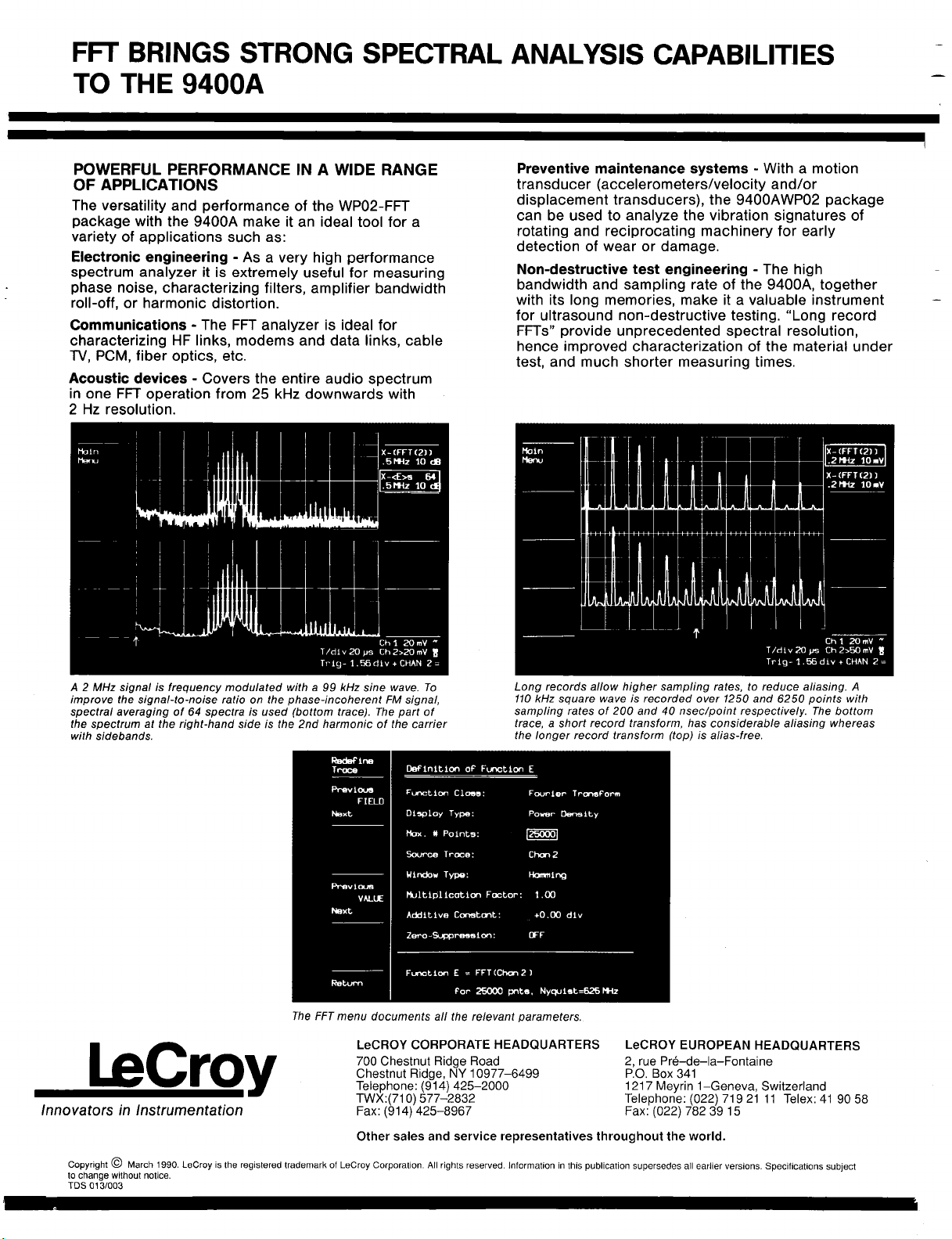
POWERFUL PERFORMANCE IN A WIDE RANGE
OF APPLICATIONS
The versatility and performance of the WP02-FFT
package with the 9400A make it an ideal tool for a
variety of applications such as:
Electronic engineering - As a very high performance
spectrum analyzer it is extremely useful for measuring
phase noise, characterizing filters, amplifier bandwidth
roll-off, or harmonic distortion.
Communications - The FFT analyzer is ideal for
characterizing HF links, modems and data links, cable
TV, PCM, fiber optics, etc.
Acoustic devices - Covers the entire audio spectrum
in one FFT operation from 25 kHz downwards with
2 Hz resolution.
Preventive maintenance systems - With a motion
transducer (accelerometers/velocity and/or
displacement transducers), the 9400AWP02 package
can be used to analyze the vibration signatures of
rotating and reciprocating machinery for early
detection of wear or damage.
Non-destructive test engineering - The high
bandwidth and sampling rate of the 9400A, together
with its long memories, make it a valuable instrument
for ultrasound non-destructive testing. "Long record
FFTs" provide unprecedented spectral resolution,
hence improved characterization of the material under
test, and much shorter measuring times.
X- (FFT (2))
.2MHz 10mY
T/dry 20 ~s Ch 2>~] mV
Trlg- 1.56 dLv + CHAN 2 =
A 2 MHz signal is frequency modulated with a 99 kHz sine wave. To
improve the signal-to-noise ratio on the phase-incoherent FM signal,
spectral averaging of 64 spectra is used (bottom trace). The part
the spectrum at the right-hand side is the 2nd harmonic of the carrier
with sidebands.
The FFT menu documents all the relevant parameters.
LeCROY CORPORATE HEADQUARTERS
700 Chestnut Ridge Road
LeCroy
Innovators in Instrumentation
Copyright @ March 1990. LeCroy is the registered trademark of LeCroy Corporation. All rights reserved, information in this publication supersedes all earlier versions. Specifications subject
to change without notice.
TOS 013/003
Chestnut Ridge, NY 10977-6499
Telephone: (914) 425-2000
TWX:(710) 577-2832
Fax: (914) 425-8967
Other sales and service representatives throughout the world.
Long records allow higher sampling rates, to reduce aliasing. A
110 kHz square wave is recorded over 1250 and 6250 points with
sampling rates of 200 and 40 nsec/point respectively. The bottom
trace, a short record transform, has considerable aliasing whereas
the longer record transform (top) is alias-free.
LeCROY EUROPEAN HEADQUARTERS
2, rue Pr@-de-la-Fontaine
P.O. Box 341
1217 Meyrin 1-Geneva, Switzerland
Telephone: (022) 719 21 11 Telex: 41 90
Fax: (022) 782 39
Ch 1 20 mV
~
Page 26

FUNCTIONAL DESCRIPTION
FOURIER PROCESSING
Fourier processing is a mathematical technique
which permits a time-domain waveform to be
described in terms of frequency-domain magnitude
and phase, or real and imaginary spectra. In spectral analysis, a waveform can be sampled and digitized, then transformed by a discrete Fourier trans-
form (DFT). Fast Fourier Transforms are a set of
algorithms used to reduce the computation time
(by better than a factor of 100 for a 1000 point
FFT) needed to evaluate a DFT. The principal
advantage of the FFT is the rapidity with which it
can analyze large quantities of waveform samples.
In effect, using standard measurement techniques,
it converts a time-domain instrument into digital
spectrum analyzer.
The WP02 Fast Fourier Processing Package enhances
the outstanding features of the LeCroy 9400A Digital
Oscilloscope. It provides high resolution, wide-band
spectrum analysis capabilities along with sophisticated window functions and fast processing.
FFT AND THE LeCROY 9400A DIGITAL
OSCILLOSCOPE
In FFT mode, the 9400A provides measurement capabilities superior to those of common swept spectrum
analyzers.
In particular, it is now possible to perform spectral
analysis on continuous and single events at an eco-
nomic price. And it enables users to obtain time and
frequency values simultaneously and to compare
phases of the various frequency components with
each other. Rather than the commonly used "power of
two" record lengths the routines used in the WP02
package feature decimal record lengths, which can be
selected in a 1-2-5 order. Resulting spectra are therefore also calibrated in convenient decimal Hertz
values.
The FFT’s digital nature ensures high accuracy, stability and repeatability. These are strongly supported by
the 9400A’s superb DC and dynamic accuracy specifications, such as standard +2%, optional 4-1%, DC
accuracy, high effective-bit count and increased resolution through signal averaging and dithering.
With the 9400A, signals may be acquired and processed simultaneously using Channels 1 and 2. This is
particularly useful when looking for common frequency-domain characteristics in both signals or for
characterization of networks.
IMPROVED RESOLUTION
The Fast Fourier Transform calculates equally-spaced
frequency components from DC to the full 9400A
bandwidth. By lowering the sampling rate, it is possible to make measurements with 1 milli-Hertz resolu-
tion up to 12,5 Hz (Nyquist). By increasing the sampling rate to 5 gigasamples/sec (200 psec/point)
Random Interleaved Sampling mode, the widest resolution becomes 50 MHz and the Nyquist frequency
2.5 GHz... comfortably above the highest frequency
components recordable by the 9400A, thus virtually
eliminating aliasing effects.
VERSATILE WINDOW FUNCTIONS
The WP02-FFT software provides a selection of window functions, designed to minimize leakage and to
maximize spectral resolution of single and non-cyclic
events. These include the familiar rectangular or
unmodified window typically used for transient events,
the von Harm (Planning) and Hamming windows for
continuous signals, and, in addition, Flattop and
Blackman-Harris windows for more precise amplitude
(power) measurements or strong suppression of side
lobes respectively.
Furthermore, user-defined window functions may be
loaded onto the 9400A via the GPIB interface. Through
multiplication, they modify the acquired signal follow-
ed by FFT in an automated fashion.
SPECIFICATIONS
VERTICAL ANALOG SECTION
Inputs: two; BNC connectors.
Sensitivity: 5 mV/div to 1 V/div at 50 £~ impedance
and 5 mV/div to 5 V/div at 1 M£) impedance; detents
at 1-2-5, variable 1:2.5.
DC accuracy: standard <_ _+ 2%; optional _< _+ 1°.
Bandwidth (-3 dB):
@ 50 (5: DC - 175 MHz at 10 mV/div, up to
225 MHz at 1 V/div;
DC - 150 MHz at 5 mV/div.
@1 M~2 AC: 10 Hz-100 MHz typical
@1 M~ DC: DC-100 MHz typical
Bandwidth limiter: 30 MHz (-3 dB).
Input impedance: 1 M£~//50 pF and 50 £2
characteristic.
Maximum input: 250 V (DC + peak AC) at 1 M~
5 V DC (500 mW) or 4- 10 V peak AC at 50 ~2.
Offset: _+ 8 divisions in 0.04-division increments.
MEMORIES
Acquisition memory: 32K x 8 bits per channel
(CH1 and CH2).
Reference memory: 32K x 16 bits per reference
memory (C and D).
Function memory: 32K x 16 bits per function memory
(E and F).
The content of the acquisition and function memories
can be stored in reference memories C and D.
Record length selection for FFT
Function memories E and F only: 50-25000 data
points in 9 steps in 1-2-5 sequence. Record lengths
are selected by decimation after signal acquisition.
This implies that the Nyquist criterion can be adjusted
and optimized after signal acquisition and prior to FFT
execution.
Page 27

Blackman-Harris
Flattop
REMOTE CONTROL
All front-panel controls and WP01 and WP02
processing functions are fully programmable via the
9400A GPIB and RS-232-C interfaces. Simple
English-like mnemonics are used.
STORED FRONT PANELS
Up to 7 front-panel setups, including WP01 and WP02
menu settings can be stored and recalled by the
menu buttons at the left side of the 9400A screen.
WP02-FFT INSTALLATION
A WP02-FFT package may be retrofitted to a LeCroy
9400A Digital Oscilloscope. The WP01 Signal
Processing hardware and software is a prerequisite
for installation of WP02.
Hamming
von Hann (Hanning)
The sum of two 1 V p-p sinusoids of 500 kHz and 527.5 kHz is
digitized over 2,500 points and transformed to the frequency domain.
4 different window functions are applied to indicate their effect on
leakage suppression and spectral resolution. The vertical scale factor
is 10 dB/div, 80 dBm full scale.
Long records give wide frequency span. FFT of 1000 Hz sineamplitude modulated square wave, recorded over 25,000 points,
shows harmonics up to 25 kHz. Expansion shows sidebands at 10 Hz
and -30.1 dB.
ORDERING INFORMATION
Oscilloscope and Options
Code
9400A
9400AOP01 High-precision option (+_ 1% DC accuracy)
9400AWP01
9400AWP02Fast Fourier processing option (requires
9400AMS01 Mass storage and remote control package,
9400AIM01 GPIB interface for IBM-PCC computers
Oscilloscope Accessories
OM9400A
SM9400A Service Manual
CA9001
CA9002 Camera adapter (35 mm) with Hood
CS9400 Certified Calibration
DP9001 Digital Plotter, 8-pen A4 size
OC9001 Oscilloscope Cart
RM9400
SG9001 High-voltage protector
TC9001 Transit Case
TC9002 Protective Cover
Description
Digital Oscilloscope
Waveform processing option
9400AWP01 )
including an IBM lap-top controller, interface,
cables and software
Operator’s Manual
Camera (using Polaroid film) and Hood
Adapter Kit for Rack Mounting
Page 28

FREQUENCY
Frequency range: DC to > 175 MHz.
Frequency resolution: 1 mHz to 50 MHz.
Nyquist frequency range: 25 mHz to 2.5 GHz.
Frequency scale factors; 5 mHz/div to 500 MHz/div in
1-2-5 sequence.
Frequency accuracy: 0.008% at center lobe.
Horizontal expansion: up to 100 times.
Cursors: Differential (arrows) and absolute (crosshair)
provide frequency and related amplitude measurements.
AMPLITUDE AND PHASE
General
Amplitude accuracy: see window functions table below.
Signal overflow: A warning indication is provided at
the top of the 9400A display when the input signal
exceeds the ADC range.
DC suppression: selected via the menu (ON/OFF),
removes DC component prior to FFT execution.
Cursors: Horizontal bars provide differential amplitude
measurements.
Number of traces: Time domain and frequency
domain data can be displayed simultaneously (up to
4 traces).
Spectrum Display Formats and Scaling
Real spectrum, in V/div, zero base line at 0 div (center
of screen).
Imaginary spectrum in V/div, zero base line at 0 div.
Power spectrum in dBm.
Power spectral density in dBm.
Frequency Domain Averaging up to 200 spectra for
power, PSD or magnitude.
Log display applies to power and PSD spectra in
10, 5, 2 or 1 dB/div; 80 clB display range.
Markers at left edge of screen give absolute dBm
reference (0 dBm is 1 mW into 50 ~).
Phase
Phase range: + 180 degrees to - 180 degrees.
Phase accuracy: ___ 5 degrees.
Phase scale factor: 50 degrees/div.
Zero base line: 0 div (center of screen).
Calibrated Vertical Expansion
All spectra formats, up to 10 times, in 1-2-5 sequence.
Window Functions
Selected in menu: Rectangular, von Hann (Hanning),
Hamming, Flattop, Blackman-Harris and user
definable. The table below gives filter pass band
shape and resolution:
FILTER PASS BAND AND RESOLUTION
Window
type
Rec-
tangular
von Hann
Hamming
Flattop
Blackman.
Harris
Filter band.
width at Highest
6dB side lobe Loss width
(freq. bins) (dB)
1.21
2.00 --32
1.81
1.78 --44 0.01
1.81 --67
--13 3.92 1.0
--43 1.78 1.36
Scallop Noise band-
(dB at bin) (freq. bins)
1.42 1.5
2.96
1.13 1.71
Definitions
Filter bandwidth at -6dB characterizes the frequency
resolution of the filter.
Highest side lobe indicates the reduction in leakage
of signal components into neighboring frequency bins.
Scallop loss gives amplitude accuracy of the
magnitude spectrum.
Noise bandwidth is the bandwidth of an equivalent
rectangular filter.
FFT EXECUTION TIME
FFT execution times, including window calculations
and display generation, are provided in the graph
below:
z.c
,_0
v
LU
5-
/
/
X
L~
u_
/
jJ
50
WP01 SIGNAL AVERAGING/ARITHMETIC
PROCESSING (Prerequisite for WP02)
Summation averaging: 10-1,000,000 signals.
Continuous averaging: infinite number of signals,
weighting factors 1, 3, 7, 15, 63, 31,127.
Waveform arithmetic: +, -, *, +.
Waveform functions: integration, differentiation,
square, square root, negation (inversion).
Smoothing: 1-, 3-, 5-, 7-, 9-point filters.
Extrema: records extreme values (envelopes) over
programmable number of sweeps.
CHAINING OF OPERATIONS
Two functions can be automatically chained using
functions E and F.
Examples: fnE = CH1 * CH2
Manual chaining using memories C and D for
intermediate results may continue indefinitely.
125 250 625
fnF = FFT of fnE
fnE = FFT of CH1
fnF = Integral fnE
/
/
1250 2500 6250
RECORD LENGTH (Points)
12500 25000
/
m
Page 29

SECTION I
GENERAL INFORMATION
I.I
Warranty
LeCroy warrants its oscilloscope products to operate within
specifications under normal use, and services them for a period of two
years from the date of shipment. Spares, replacement parts and repairs
are warranted for 90 days. Software is thoroughly tested but is
supplied "as is" with no warranty of any kind covering detailed
performance. Accessory products not manufactured by LeCroy are covered
solely by the warranty of the original equipment manufacturer.
In exercising this warranty, LeCroy will repair or, at its option,
replace any product returned to the Customer Service Department or an
authorized service facility within the warranty period, provided that
the warrantor’s examination discloses that the product is defective due
to workmanship or materials, and that the defect has not been caused by
misuse, neglect, accident or abnormal conditions or operation.
The purchaser is responsible for the transportation and insurance
charges arising from the return of products to the servicing facility.
LeCroy will return all in-warranty products with transportation
prepaid.
This warranty is in lieu of all other warranties, expressed or implied,
including but not limited to any implied warranty of merchantability,
fitness, or adequacy for any particular purpose or use. LeCroy shall
not be liable for any special, incidental, or consequential damages,
whether in contract, or otherwise.
1.2
Assistance and Maintenance Agreements
Answers to questions concerning installation, calibration, and use of
LeCroy equipment are available from the Customer Service Department,
700 Chestnut Ridge Road, Chestnut Ridge, New York 10977-6499, U.S.A.,
(914)578-6097, and I01 Route du Nant drAvril, 1217 Meyrin i, Geneva,
Switzerland, (41)22/782-33-55, or your local field engineering office.
LeCroy offers a selection of customer support services. For example,
maintenance agreements provide extended warranty and allow the customer
to budget maintenance costs after the initial two year warranty has
expired. Other services requested by the customer such as installation,
training, on-site repair, and addition of engineering improvements are
made available through specific Supplemental Support Agreements.
General Information
I-i
Page 30

1.3 Documentation Discrepancies
LeCroy is committed to providing state-of-the-art instrumentation and
is continually refining and improving the performance of its products.
While physical modifications can be implemented quite rapidly, the
corrected documentation frequently requires more time to produce.
Consequently, this manual may not agree in every detail with the
accompanying product. There may be small discrepancies in the values of
components for the purposes of pulse shape, timing, offset, etc., and,
occasionally, minor logic changes. Where any such inconsistencies
exist, please be assured that the unit is correct and incorporates the
most up-to-date circuitry.
1.4 Service Procedure
Products requiring maintenance should be returned to the Customer
Service Department or authorized service facility. If under warranty,
LeCroy will repair or replace the product at no charge. The purchaser
is only responsible for the transportation charges arising from return
of the goods to the service facility.
For all LeCroy products in need of repair after the warranty period,
the customer must provide a Purchase Order Number before any equipment
which does not operate correctly can be repaired or replaced. The
customer will be billed for the parts and labor for the repair as well
as for shipping.
1.5 Return Procedure
To determine your nearest authorized service facility, contact the
factory or your field office. All products returned for repair should
be identified by the model and serial numbers and include a description
of the defect or failure, name and phone number of the user, and, in
the case of products returned to the factory, a Return Authorization
Number (RAN). The RAN may be obtained by contacting the Customer
Services Department in New York on 914-578-6059, in Geneva on
(022) 782-33-55 or your nearest sales office.
Return shipments should be made prepaid. LeCroy will not accept C.O.D.
or Collect Return Shipments. Air-freight is generally recommended.
Wherever possible, the original shipping carton should be used. If a
substitute carton is used it should be rigid, and should be packed such
that the
excelsior
shipment,
displayed
to the proper department within LeCroy.
product is surrounded with a minimum of four inches of
or a similar shock-absorbing material. In addressing the
it is important that the Return Authorization Number be
on the outside of the container to ensure its prompt routing
General Information
1-2
Page 31

1.6
Initial Inspection
It is recommended that the shipment be thoroughly inspected immediately
upon delivery to the purchaser. All material in the container should be
checked against the enclosed Packing List. LeCroy cannot accept
responsibility for shortages in comparison with the Packing List unless
notified promptly. If the shipment is damaged in any way, please
contact the factory or local field office immediately.
1-3
General Information
Page 32

Page 33

2.1 Introduction
The LeCroy 9400A is a high-performance digital oscilloscope suited to
research and to test and measurement applications. It is used to
capture, analyze, display and archive electrical waveforms in fields
such as electronic engineering, physics research, automated testing and
measurement, telecommunications, electromagnetic pulse and interference
measurement, LIDAR technology and ultrasonics research.
2.2 9400A Architecture
The 9400A has been built around the powerful 68000 microprocessor which
is used by the unit to perform computations and control oscilloscope
operation.
SECTION 2
PRODUCT DESCRIPTION
Att~uator Amplifier 5omple 4. AOC
AC
Offsel Gain ....
hold memory
9400A BLOCK DIAGRAM
Acqulsition Processor +
interfaces
r15112C
!
""
Figure 2.1
2-1
Product Description
Page 34

All front panel rotary knobs and push buttons are constantly monitored
by the internal processor, and front panel setups are rapidly
reconfigured via the unit’s internal 16-bit bus. Data are quickly
processed according to the selected front panel setups, and are
transferred to the acquisition memory for direct waveform display or
stored in the 9400A’s reference memories.
The 68000 controls the unit’s two RS-232-C ports which are used to
directly interface the 9400A to a digital plotter, remote terminal or
other slow-speed device and also controls GPIB (IEEE-488) operation
when the 9400A is equipped with the I/O option, OP02.
2.3
ADCs and Memories
The 9400A’s two identical input channels are equipped with a
I00 megasample/second (megasample/sec), 8-bit ADC and a 32 kiloword
acquisition memory (See Figure 2.1). This dual ADC architecture ensures
absolute amplitude and phase correlation, maximum ADC performance for
both single and dual channel acquisition modes, large record lengths
and high time resolution.
The 9400A’s two 32K acquisition memories simplify transient capture by
providing very long waveform records that capture waveform features
even when trigger timing is uncertain. In addition, very accurate time
measurement is made possible by a digitally controlled zoom providing
an expansion factor of up to I00 times the time base speed.
The 9400A oscilloscope is capable of acquiring and storing repetitive
signals at a Random Interleaved Sampling rate of 5 gigasamples/second
(gigasamples/sec). An exclusive high-precision time digitizing
technique enables measurement of repetitive signals to a bandwidth of
175 MHz at an effective measuring interval of 200 psec.
The 9400A’s very low aperture uncertainty of 10 psec assures precision
measurements over its entire range as indicated by the table below:
Overall* dynamic accuracy (typical), RMS sine wave curve fit
Input Frequency (MHz)
Signal-to-noise Ratio (dB) 41.9
Effective bits
* including the front-end amplifier, sample and hold and ADC
1 10 50 100 175
41.9 41.9 37.1 29.9
7.0
9400A PERFORMANCE
Table 2.1
2-2
7.0
7.0 6.2 5.0
Product Description
Page 35

2.4 Trigger
The 9400A’s digitally-controlled trigger system offers facilities such
as pre-trigger recording, bi-slope and window triggering, sequence and
roll modes in addition to the standard operating modes of Auto, Normal
and Single (Hold). The trigger source can be external or can be either
of the two inputs, and the coupling is selected from AC, LF REJect,
HF REJect and DC.
2.5 Automatic Calibration
The 9400A has an automatic calibration facility that ensures overall
vertical accuracies of ± 2% (optionally ± 1%) and ± 20 psec RMS for the
unit’s crystal-controlled time base.
The time base is calibrated each time the 9400A’s time base control is
adjusted to a new TIME/DIV setting; vertical gain and offset
calibration take place each time the front panel fixed gain control for
either CHAN i or CHAN 2 is adjusted to a new VOLTS/DIV setting.
Calibration of both channels also takes place each time the BANDWIDTH
LIMIT push button is pressed.
Further information on automatic
Section 9.4, "Auto-calibration".
2.6 Display
The 9400A’s large 12.5 cm x 17.5 cm (5 x 7 inches) screen displays
analog waveforms with high precision and serves as an interactive,
user-friendly interface via a set of screen-oriented push buttons
located immediately to the left and right of the CRT.
The oscilloscope displays up to four waveforms, while simultaneously
reporting the parameters controlling signal acquisition. In addition,
the screen presents internal status and measurement results, as well as
operational, measurement, and waveform analysis menus.
A hard copy of the 9400A’s screen is available via the unit’s dedicated
plotter port.
2.7 Manual and Programmed Control
The 9400A’s front panel layout and operation will be very familiar to
users of analog oscilloscopes. The interactive software menus assist in
quickly utilizing the recording and processing capability of the 9400A
to its full potential.
calibration may be found in
2-3
Product Description
Page 36

The 9400A has also been designed for remote control operation in
automated testing and computer aided measurement applications. The
entire measurement process, including dynamic modification of front
panel settings and display organization, can be controlled via the rear
panel RS-232-C and optional GPIB (IEEE-488) ports. GPIB control
enables direct interfacing between the 9400A and a host computer at
data transfer rates of up to 400 kilobytes/sec.
The LeCroy 9400A is capable of storing up to seven front panel setups
which may be recalled either manually or by remote control, thus
ensuring rapid oscilloscope front panel configuration. When the power
is switched on, the 9400A’s front panel settings are the same as when
it was last used.
2-4
Product Description
Page 37

SECTION 3
INSTALLATION
3.1
3.2 Operating Voltage
Safety Information
The 9400A has been designed to operate from a single-phase power source
with one of the current-carrying conductors (neutral conductor)
ground (earth) potential. Operation from power sources in which both
current-carrying conductors are live with respect to ground (such as
phase-to-phase on a tri-phase system) is not recommended, as the 9400A
is equipped with over-current protection for one mains conductor only.
The 9400A is provided with a three-wire electrical cord containing a
three-terminal polarized plug for mains voltage and safety ground
connection. The plug’s ground terminal is connected directly to the
frame of the unit. For adequate protection against electrical hazard,
this plug must be inserted into a mating outlet containing a safety
ground contact.
Prior to powering up the unit, make certain that the mains voltage for
your area corresponds to the mains voltage value appearing in the
window of the selector box at the rear of the 9400A.
The operating voltage for the 9400A is either 115 V or 220 V at 48 to
62 Hz. Switching from one mains voltage to another is not possible. If
the mains voltage appearing in the window differs from that used in
your area contact the nearest LeCroy sales office or distributor.
*CAUTION*
If a 9400A set for 115 V is plugged into a 220 V power source, severe
damage can occur. Before powering up the unit, ensure that the corect
line voltage has been set.
Installation
3-i
Page 38

3.3
Switching on the 9400A
Switch on the 9400A by setting the POWER switch (26) to the
position.An auto-calibration takes place and the grid is displayed
after approximately 15 seconds.
Note that the 9400A is reset to the configuration it was in prior being
to switched off.
3-1
Installation
Page 39

SECTION 4
DISPLAY LAYOUT
The 9400A’s CRT area is divided between the centrally located grid and
six other fields. Traces from the acquisition or reference memories are
displayed on the grid. A dual grid system is also available by pressing
push button 14 (see Figure 1.1). The six fields are used to display
such information as interactive menu queries and responses, current
acquisition parameters, relative and absolute time and voltage
measurements, and messages to assist the user.
°.
..
4.1 Menu Field (I)
This field is divided into nine sub-fields associated with menu keys
2-10. Each field may display the name of a menu or perform an operation
when the related menu key is pressed. The lowest field and related
Return push button (i0) are used to restore the higher menu level.
DISPLAY LAYOUT
Figure 4.1
Display Layout
4-1
Page 40

4.2 Time and Frequency Field (II)
When the Marker cursor is activated by pressing push button (18), this
field displays the time difference between the Marker cross-hair and
the point of triggering (common for all displayed traces).
When the Time cursors are activated by pressing push button (17), two
readings are indicated. The left-hand reading indicates the time
interval between the Reference and Difference arrowhead cursors, while
the right-hand reading indicates the frequency corresponding to 1/(Time
interval).
Trigger Delay Field (III)
This field indicates one of the two trigger delay modes. In the
pre-trigger mode, an upward-pointing arrow appears below the bottom
line of the trace display grid, as shown in Figure 4.1. It is
adjustable from 0 to 10 divisions, corresponding to a 0 to 100Z
pre-trigger setting. In the post-trigger mode, this arrow is replaced
by a leftward-pointing arrow next to the post-trigger indication (in
decimal fractions of a second) at the bottom of the grid. The maximum
post-trigger setting corresponds to 10000 screen divisions.
4.4
4.5 Displayed Trace Field (V)
Abridged Front Panel Status Field (IV)
This is a short-form display of the data acquisition parameters, and is
updated whenever the 9400A’s front panel controls are manipulated. This
field indicates vertical sensitivities, input couplings, time base and
trigger conditions.
See Section 5 for a detailed list of front panel parameters (including
the absolute value of input offset).
The Displayed Trace field is associated with push buttons 45-50. The
data displayed in this field are the identity of the displayed trace,
and the current time base and sensitivity settings for the acquired
signal, as well as an indication of the position of the VAR sensitivity
vernier (28). The symbol ">" appears when the vernier is not in the
detent position (i.e. not in the fully clockwise position). Whenever
Measurement Cursors (16, 17, 18) are activated, absolute or relative
waveform voltage data are displayed in this field.
A frame formed around one of the upper six signal sources in the
Displayed Trace field indicates which of the traces is to be acted upon
during manipulation of the various display controls ((39) through (43).
Display Layout
4-2
Page 41

4.6
Message Field (VI)
Messages appearing in field (Vl) indicate the 9400A’s current
acquisition status or report improper manipulation of the front panel
controls. The following figure illustrates a typical message displayed
in the Message field.
Channel 1
5~e 20mV
Channel 2
5~ .5 V
T/dlv 5~m 012 .5 V
Ch~ 20mV
~
Trig S.O8dtv+CHAN ~
EXAMPLE of MESSAGE FIELD DISPLAY
Figure 4.2
********
*NOTE*
********
In the following sections, Roman numerals in parentheses refer to the
display field numbering scheme in Figure 4.1. Arabic numerals relate to
the numbering scheme used to refer to front and rear panel controls and
connectors in Figures i.I and 1.2.
Display Layout
4-3
Page 42

Page 43
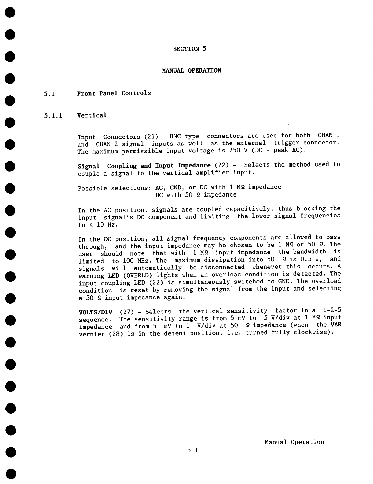
SECTION 5
MANUAL OPERATION
5.1
5.1.1 Vertical
Front-Pmlel Controls
Input Connectors (21) - BNC type connectors are used for both CHAN
and CHAN 2 signal inputs as well as the external trigger connector.
The maximum permissible input voltage is 250 V (DC + peak AC).
Signal Coupling and Input Impedance (22) - Selects the method used
couple a signal to the vertical amplifier input.
Possible selections: AC, GND, or DC with I M~ impedance
In the AC position, signals are coupled capacitively, thus blocking the
input signal’s DC component and limiting the lower signal frequencies
to < i0 Hz.
In the DC position, all signal frequency components are allowed to pass
through, and the input impedance may be chosen to be I M~ or 50 ~. The
user should note that with I M~ input impedance the bandwidth is
limited to I00 MHz. The maximum dissipation into 50 ~ is 0.5 W, and
signals will automatically be disconnected whenever this occurs. A
warning LED (OVERLD) lights when an overload condition is detected. The
input coupling LED (22) is simultaneously switched to GND. The overload
condition is reset by removing the signal from the input and selecting
a 50 ~ input impedance again.
DC with 50 ~ impedance
VOLTS/DIV (27) - Selects the vertical sensitivity factor in a 1-2-5
sequence. The sensitivity range is from 5 mV to 5 V/div at I M~ input
impedance and from 5 mV to I V/div at 50 ~ impedance (when the VAR
vernier (28) is in the detent position, i.e. turned fully clockwise).
Manual Operation
5-1
Page 44

Menu
T/d:l.v .2jJ Ch2 .5 V Trlg .2O V - ~ =
DISPLAY of VERTICAL SENSITIVITY PARAMETERS
in the ABRIDGED PANEL STATUS FIELD
Figure 5.1
The VOLTS/DIV setting for CHAN 1 and CHAN 2 is displayed, along with
signal input coupling and various other data, in the Abridged Panel
Status Field (IV), see Figure 4.1. It may be modified either manually
or via remote control, and is immediately updated.
Whereas acquisition control settings displayed in the Abridged Panel
Status Field (IV) are immediately updated upon manual or remote modifications of the VOLTS/DIV or TIME/DIV settings, the control settings in
the Displayed Trace field (V), corresponding to the conditions under
which the waveform was stored, are updated with every trigger.
C~’1 5mVll
I:h.....d. t
.IJ~ IluN
ChmrmL 2
.e~, v
T/dlv’JiOn.. Oh2 .2 Y ,,
Trl~i- .20V - EXT -
SENSITIVITY DATA DISPLAYED in the ABRIDGED PANEL
STATUS FIELD and in the DISPLAYED TRACE FIELD
Figure 5.2
5-2
.~L V~
Manual Operation
Page 45

VAR (28) - Verniers provide continuously variable sensitivity within
the VOLTS/DIV settings and extend the maximum vertical sensitivity
factor to up to 12.5 V/div. Variable sensitivity settings are indicated
by the ">" symbol in the lower portion of the Abridged Front Panel
Status field and the calibrated value appears in the Total V/div field
of the Panel Status menu (See Section 5.2.2). (Minimum sensitivity
achieved by rotating the vernier counter-clockwise.)
VERTICAL OFFSET (32) - This control vertically positions the displayed
trace. The maximum offset is ± 1 grid height (± 8 divisions) from the
center of the screen, and is manually adjustable (or programmable)
0.04 division increments. A pair of upward- or downward-pointing
double-shaft arrows indicates when the trace has been positioned
outside the grid, as shown in Figure 5.3.
ir
w
UPWARD and DOWNWARD POINTING, DOUBLE SHAFT ARROWS
INDICATING THAT CHANNEL 1 and 2 ARE OFF SCREEN
Figure 5.3
PROBES - Two Model P9010 passive probes are supplied with the 9400A.
These probes have I0 M~ input impedance and 6 pF capacitance. The
system bandwidth with P9010 probes is DC to I00 MHz in 1M~ DC
coupling, and < I0 Hz to I00 MHz in AC coupling. Active FET probes
(Tektronix models P6201, P6202a and P6230) may be powered via probe
power connectors on the rear panel.
Manual Operation
5-3
Page 46

PROBE CALIBRATION (19, 20) Tocal ibrate the P901 0 Prob e, conn ect it
to the CHAN 1 or CHAN 2 BNC connector (21). Connect the probe’s
grounding alligator clip to the front panel ground lug (20) of the
oscilloscope and the tip to lug (19).
Adjust the 9400A’s front panel controls as described in Section 8.1. In
case of over- or undershooting of the displayed signal, it is possible
to adjust the P9010 Probe by inserting the small screwdriver, supplied
with the probe package, into the trimmer on the probe’s barrel and
turning it clockwise or counter-clockwise to achieve an optimal square
wave contour.
BANDWIDTH LIMIT (50) Byset ting the BAND~rlDTH LIMI T butt on to O N t he
bandwidth can be reduced from 175 MHz to 30 MHz (-3 dB). Bandwidth
limiting may be useful in reducing signal and system noise or
preventing high-frequency aliasing for single-shot events at time bases
below 50 ~sec/division.
5.1.2 Time Base
TIME/DIVISION (36) This control se lects th e time pe r division in a
1-2-5 sequence from 2 nsec to 100 sec. The time base is displayed in
the Abridged Panel Status field (IV) as well as in the Displayed Trace
field (V). The time bas~ is crystal-controlled and features an overall
-~.
accuracy better than I0
SAMPLING MODES
Three sampling modes are possible with the 9400A depending on the
time-base setting selected by the user. They are:
Random Interleaved Sampling (RIS)
*
Single Shot (SS)
*
* Roll Mode
Random Interleaved Sampling (RIS)
At time-base settings from 2 to 20 nsec/div, the 9400A automatically
uses the RIS mode for signal acquisition. Repetitive waveforms and a
stable trigger are required. Waveforms can be digitized with sampling
intervals as small as 200 psec for an equivalent sampling rate of up
to 5 gigasamples/sec.
5-4
Manual Operation
Page 47

Between the 50 nsec and 2 psec/div range of time base settings, the
user may select the RIS acquisition mode by pressing the INTERLEAVED
SAMPLING button (37).
Single Shot
For time base settings from 50 nsec to 200 msec/div the 9400A records
the waveform in a single acquisition. Sampling rates up to
i00 megasamples/sec are possible in the Single Shot mode.
Roll
From 500 msec to I00 sec/div, the 9400A samples continuously. Each
digitized point updates the display, resulting in a trace moving from
right to left similar to that produced by a strip-chart recorder.
TIME BASE
(TIME/DIV)
2.0 nsec
5.0 nsec
i0.0 nsec 200 psec
20.0 nsec 200 psec
50.0 nsec
0.I ~sec
0.2 ~sec
0.5 psec 200 psec i0.0 nsec 24000 500
1.0 psec 400 psec I0.0 nsec 24800 i000
2.0 ~sec
5.0 psec I0.0 nsec 5000
I0.0 psec i0.0 nsec i0000
20.0 psec I0.0 nsec 20000
50.0 Bsec
0.i msec
0.2 msec 80.0 nsec
0.5 msec
1.0 msec
2.0 msec 0.8 ~sec
5.0 msec
I0.0 msec
20.0 msec
50.0 msec 20.0 ~sec
0.I sec
0.2 sec 80.0 ~sec
SAMPLING RATE
TIME/POINT
RIS SS RIS SS
200 psec I00
200 psec 250 ---
200 psec I0.0 nsec 2500 50
200 psec I0.0 nsec 5000 I00
200 psec i0.0 nsec 10000 200
800 psec I0.0 nsec 25000 2000
20.0 nsec 25000
40.0 nsec
0.2 psec 25000
0.4 psec
2.0 psec
4.0 Hsec 25000
8.0 psec
40.0 psec
DISPLAYED RECORD
LENGTH (Points)*
500
I000
25000
25000
25000
25000
25000
25000
25000
25000
25000
5-5
Manual Operation
Page 48

TIHE BASE
SA}4PLING RATE
TIME/POINT
DISPLAYED RECORD
I.RNCTH (Points)*
(TIME/DIV)
0.5 sec
1.0 sec
2.0 sec
5.0 sec
I0.0 sec
20.0 sec
50.0 sec
I00.0 sec ---
Note: When the 9400A is remotely read out, the entire memory content of
32,000 words is available at all time base speeds for single shot and
roll modes. 24,000 samples are available for all RIS settings except at
I and 2 psec/div, when 24,800 and 25,000 samples respectively are
available.
LIST of SAMPLING MODES, SAMPLING RATE,
RIS SS
ROLL NODE
0.2 msec
0.4 msec
0.8 msec
2.0 msec
4.0 msec
8.0 msec
20.0 msec
40.0 msec
and DISPLAYED RECORD LENGTH
Table 5.1
RIS SS
--- 25000
--- 25000
--- 25000
25000
25000
25000
25000
25000
5.1.3 Trigger
EXTERNAL Trigger Input (24) - This BNC connector input accepts
external trigger signal of up to 250 V (DC + peak AC). Input impedance
is 1M~ in parallel with < 30 pF. The triggering frequency is >200 MHz.
Trigger SOURCE (23) - Selects the trigger signal source as follows:
CHAN 1 - Selects the Channel i input signal.
CHAN 2 - Selects the Channel 2 input signal.
LINE - Selects the line voltage powering the oscilloscope in order
to provide a stable display of signals synchronous with the power
line.
Manual Operation
5-6
Page 49

EXT - With the Trigger SOURCE set to EXT, a signal applied to the
BNC connector labeled EXTERNAL can be used to trigger the scope
within a range of ± 2 V.
EXT/IO - With the Trigger SOURCE set to EXT/10, a signal applied
to the BNC connector labeled EXTERNAL, can be used to trigger the
scope within a range of ± 20 V.
Trigger COUPLING (30) - Selects the type of signal coupling to the
trigger circuit:
AC Trigger - Signals are capacitively coupled; DC levels are
rejected and frequencies below 60 Hz are attenuated.
LF REJ - Signals are coupled via a capacitive high-pass filter
network. DC is rejected and signal frequencies below 50 kHz are
attenuated. The LF REJ trigger mode is used whenever triggering on
high frequencies is desired.
BF RBJ - Signals are DC-coupled to the trigger circuit and a
low-pass filter network attenuates frequencies above 50 kHz. The
HF REJ trigger mode is used when triggering on low frequencies is
desired.
DC - All of the signal’s frequency components are coupled to the
trigger circuit. This coupling mode is used in the case of high
frequency bursts, or where the use of AC coupling would shift the
effective trigger level.
Trigger
generate a trigger.
The trigger range is as follows:
SLOPE (25) Selects th e si gnal ed ge us ed to act ivate the
circuit.
LEVBL (33) - Adjusts the level of the signal required
± 5 screen divisions - with CHAN 1 or CHAN 2 as trigger source
None (zero-crossing) with LINE as trigger source
± 2 V with EXT as trigger source
± 20 V with EXT/IO as trigger source
POS - Requires a positive-going edge of the trigger signal.
trigger
NEG - Requires a negative-going edge.
5-7
Manual Operation
Page 50

(POS/NEG) - Permits "window" triggering, i.e. triggering on either
a positive- or negative-going signal edge, whichever occurs first.
When the POS/NEG trigger slope is selected, the Trigger LEVEL
control (33) is turned counter-clOckwise for bi-slope triggering
at base line level. Turning the Trigger LEVEL control (33)
clockwise generates a variable amplitude trigger window which is
symmetrical with respect to the center of the screen (internal
trigger source) and to ground (external trigger source). When
using an internal trigger source, the user may produce an
asymmetrical window by offsetting the base line with respect to
ground via Vertical OFFSET control (32).
In the window triggering mode no trigger will occur while the
signal remains within the window. A signal which exceeds the
pre-selected limits will generate a trigger and the signal is
stored into the memory, as shown in the following figure.
Parml
STATUS
¯ M
WINDOW TRIGGERING
Figure 5.4
In the above figure the trigger level is ± 3 divisions as indicated in
the Abridged Panel Status field.
Manual Operation
5-8
Page 51

Trigger MODE (29) - Selects the mode of trigger operation as follows:
SINGLE (HOLD) - Selected using the lower button (29).
In this mode the 9400A digitizes until a valid trigger is
received. After the waveform has been acquired and displayed, no
further signals can be acquired until the SINGLE (HOLD) button has
been pressed again to re-arm the trigger circuit in preparation
for the next trigger signal. This type of acquisition provides a
simple means of recording a wide variety of transient events.
When the 9400A is in the Random Interleaved Sampling (RIS) mode,
sufficient number of triggers must be obtained to complete
waveform reconstruction, after which the waveform will be
displayed. No further signals can be acquired until the SINGLE
(HOLD) button has been pressed again.
When the 9400A is in the Roll mode (~ 500 msec/div), pressing the
SINGLE (HOLD) button causes data acquisition to immediately halt
and the display to freeze.
NORM - Selected using button (29).
When in the normal (NORM) trigger mode, the 9400A continuously
digitizes the input signal. Whenever a valid trigger is received,
the acquired waveform is displayed on the CRT, digitization starts
again and the trigger circuit is re-armed. If no subsequent
trigger is received within 2 seconds, previously acquired
waveforms are erased from the screen. The absence of a valid
trigger will thus result in a blank screen.
To retain the last acquired waveform indefinitely in the NORM
mode, the 9400A’s Auto-store feature is used. Auto-store can be
called via the Special Modes menu described in Section 5.2.5.
When the 9400A is in the RIS mode, a sufficient number (typically
200) of valid triggers is required for each display of a complete
waveform.
In the Roll mode (~ 500 msec/div), the 9400A samples the input
signals continuously. Each point is immediately updated on the
display. This results in a trace which moves from right to left
across the CRT. In the NORM mode, triggers are ignored. The only
way to halt data acquisition is to select the SINGLE (HOLD) mode
or switch the 9400A into AUTO mode and provide a trigger.
Manual Operation
5-9
Page 52

AUTO - Selected using button (29).
This mode resembles the NORM mode, except that it automatically
generates an internal trigger and forces a waveform to appear on
the screen whenever the selected trigger is not present for more
than 500 msec. When the 9400A auto-triggers, the display usually
moves in time as the trigger is not time-correlated with the input
signal.
Auto trigger can not be used when the 9400A is in the RIS mode.
When the 9400A is in the Roll mode (> 500 msec/div), it samples
input signals continuously. In the AUTO mode any valid trigger
will halt data acquisition once the trigger delay requirements
have been satisfied.
SEO_NCE - Selected using the upper button (29).
Sequence triggering enables the 9400A’s acquisition memories to be
partitioned into up to 250 segments.
Possible settings are: 8, 15, 31, 62, 125, or 250 segments.
Waveform acquisition in SEONCE mode is particularly useful in the
case of short-lived or echoed signals, such as those typically
encountered in RADAR, SONAR, LIDAR and NMR.
In this mode, the time base setting determines the total duration
(TIME/DIV x I0) of each segment. Changing the number of required
segments does not change the time base; it only affects the number
of digitized points (record length) per segment. The number
data points per division is shown in the Acquisition Parameters
display, called by pressing Panel STATUS button (2).
The display is only updated after a sufficient number of sweeps
has been acquired. If less than the required number of triggers is
available the SEQNCE acquisition may be aborted by pushing the
SEQNCE button (29) again.
The 9400A then completes the missing sweeps by auto-triggering a
sufficient number of times while setting its input coupling
temporarily to GND. Thus the artificially completed sweeps will
appear on the display as GND lines.
5-10
Manual Operation
Page 53

Number of Segments Points/Seg~nent
8
15
31
62
125
250 I01
SEQUENCE TRIGGER MODE
NUMBER OF SEGMENTS VS. RECORD LENGTH (TIME BASE: 20 usec)
Table 5.2
Neither the CHAN 1 nor CHAN 2 display is updated when the 9400A is
in the SINGLE or SEQNCE trigger mode, i.e. when no further data
are acquired. Vertical positioning of the displayed trace may
nevertheless be modified via the OFFSET control (32). The VAR
vernier (28) also remains active. However, no other parameter
modifications, such as vertical sensitivity or time changes, will
alter the display of a currently acquired waveform in CHAN 1 or
CHAN 2.
Of course, all parameters may be modified during this time by
manipulating the appropriate front panel controls, but such
modification - indicated by parameter changes in the Abridged
Front Panel Status field (IV) - will only be used when acquiring
the next trace.
2501
2001
i001
497
241
Whenever the 9400A is in the NORM or AUTO trigger mode, data are
continuously acquired and the display rapidly updated. All
modifications in acquisition parameters are thus followed quickly
by subsequent waveform acquisition which results in their
appearing to the user as changes to the CHAN 1 or CHAN 2 display.
TRIG’D and READY LEDs (31) - The TRIG’D LED indicates Whenever the
digitizing has stopped (normally after a valid trigger). The READY LED
indicates that the trigger circuit has been armed and the 9400A is
currently digitizing input signals. Upon receiving a valid trigger
signal, it will continue digitization until the trigger conditions have
been satisfied and will then display the acquired waveform.
DELAY (34) - Adjusts the degree of pre- or post-trigger delay when
recording signals in the acquisition memories. Delay operation is via a
single continuously rotating knob. Turning this knob slowly allows
minute adjustment of the trigger point; turning it quickly results in
rapid trigger point movement. The DELAY control enables pre-trigger
adjustment, displayed in %. Pre-trigger adjustment up to 100% full
scale, and post-trigger adjustment up to i0,000 divisions in 0.02
division increments are available.
Manual Operation
5-11
Page 54

The pre-trigger indicator is displayed by an upward pointing arrow on
the bottom graticule line; the post-trigger indicator is displayed in
decimal fractions of a second, preceded by a leftward-pointing arrow,
in the left-hand corner of the Trigger Delay field (III).
ZERO (35) - Resets the trigger delay from previously set positions
the leftmost graticule line (i.e. 0.0% Pre-trigger position).
5.1.4 Displaying Traces
Up to four different waveforms (out of a total of eight) may
simultaneously displayed. Whenever a trace is displayed by pressing one
of the TRACE ON/OFF buttons ((46)-(49)), the corresponding waveform
will appear on the screen together with a short description in the
Displayed Trace field (V). When several signals are being displayed
simultaneously, buttons (46)-(49) can be used as convenient trace
identifiers by repeatedly pressing one of these buttons and simply
seeing which of the displayed traces is turned ON and OFF by this
operation.
EXPAND A, B buttons (46) - Turn the displayed expansion of a waveform
ON or OFF. The expanded portion of the waveform is displayed on the
source trace as an intensified region. The default settings are;
EXPAND A operates on CHANNEL 1 and EXPAND B operates on CHANNEL 2. They
may be changed to allow expansion on any other source trace, by using
the REDEFINE button (48).
MEMORY C, D buttons (47) - Turn the display of a waveform in reference
Memories C or D ON or OFF. Acquired data may be stored into these
memories via the STORE button (I), as described in Section 5.2.1.
FUNCTION E, F buttons (48) - If your 9400A is equipped with a waveform
processing firmware option, pressing these buttons will turn the
display of a computed waveform ON or OFF. The type of computation may
be defined by pressing the REDEFINE button (45). See WPOI Waveform
Processing Option, Section I0.
CHANNEL I, 2 buttons (49) - Turn the display of signals applied
either of the input connectors (21) ON or OFF. Recording of data into
CHAN 1 and CHAN 2 acquisition memories always occurs simultaneously and
irrespective of whether the trace display is ON or OFF.
5.1.5 Display Control
Displayed traces may be modified within certain limits following
waveform acquisition.
CHAN 1 and CtlAN 2 traces are controlled by the VERTICAL and Time
The
Base controls ((27), (28), (32) and (36), (37), respectively).
5-12
Manual Operation
Page 55

Six traces, EXPAND A, B (46), MEMORY C, D (47), and FUNCTION E, F
are controlled by the Display Control knobs and buttons (39)-(45).
one trace is controllable at a time. The identity of the controlled
trace is indicated by a rectangular frame around the waveform
descriptor in the Displayed Trace field (V).
Whenever more than one of the six traces listed above are currently
displayed, the frame may be moved to the next trace by pressing the
SELECT button (44).
Horizontal POSITION knob (39) - Horizontally positions an expanded
waveform and the intensified region along the source trace. This
control is activated only after the EXPAND A and/or B buttons (46) have
been pressed to display the expanded trace. The Horizontal POSITION
knob allows the user to scroll continuously through a displayed
waveform. However, if the source trace was recorded in sequence mode
(i.e. a number of sequentially acquired traces was stored in
partitioned memory blocks), the movement of the Horizontal POSITION
knob will be discrete allowing any single segment to be selected.
The Horizontal POSITION control affects only EXPAND A, B.
Vertical POSITION knob (40) - Vertically repositions the trace.
RESET button (41) - Serves to reset previously adjusted VERT GAIN,
Vertical and/or Horizontal POSITION to the following default values:
VERT GAIN
Vertical POSITION
Horizontal POSITION
In the Common Expand mode (See Section 5.2.5.2), this button is used
synchronize the two intensified regions of EXPAND A and B.
VERT GAIN knob (42) - Turning the knob clockwise allows vertical
expansion by a factor of up to 2.5. Counterclockwise rotation allows
vertical contraction by a factor of up to 2.5. If the vernier knob is
not in the detent position it is possible to achieve vertical expansion
by a factor of up to 5.
Pressing RESET (41) returns gain control to a mid-range plateau
corresponding to a gain of I. If the 9400A is equipped with WP01, the
vertical gain is increased from 2.5 to I0 for averages, mathematics and
functions.
Same as the original trace
-
Same as the original trace
-
- Center of the original trace
5-13
Manual Operation
Page 56

TIME MAGNIFIER knob (43) - This control horizontally expands waveforms
up to I00 times.
Overall timing accuracy is improved at higher magnification factors,
since the expand function is controlled digitally and makes use of the
scope’s high number of recorded data points. This control has no effect
on MEMORY C, D or FUNCTION E, F.
SELECT button (44) - Chooses one of the traces - EXPAND A through
FUNCTION F - to be controlled via Display Control knobs and buttons
((39)-(45)). The selected trace is indicated by a rectangular
around the waveform descriptor in the Displayed Trace field (V).
Pressing the SELECT button (44) moves the rectangle to the next
displayed trace in a rolling sequence.
REDEFINE button (45) - Used to redefine the identity of the selected
waveform. EXPAND A, B traces may be redefined to be the expansion of
CHAN 1 or CHAN 2, MEMORY C or D or FUNCTION E or F (for 9400A’s
equipped with the Waveform Processing Option).
Pressing the REDEFINE button (45) calls a menu on the left-hand side
the screen enabling selection of the desired source redefinition. When
the button corresponding to this redefinition is pressed, EXPAND A or B
will be temporarily selected as the new source trace until subsequent
redefinition is performed. The default signal sources are CBAN I for
EXPAND A and CHAN 2 for EXPAND B.
It is not possible to redefine Memories C and D; Function E and F may
only be redefined if your 9400A is equipped with the Waveform
Processing Option. For scopes with this option installed, see Section
l0 which deals with the Waveform Processing Option.
5.1.6 Screen Adjustments
INTENSITY knob (12) - Adjusts the intensity of the displayed trace and
all alphanumeric readouts and messages. The INTENSITY control may be
adjusted in either manual or remote control mode.
GRID INTENSITY knob (13) - Controls grid and graticule intensity
independently of displayed trace intensity.
DUAL GRID button (14) - This button switches between single and dual
grid modes. The dual grid is useful when displaying multiple traces, in
which case the CHAN I display is permanently assigned to the upper grid
and CBAN 2 to the lower grid. All other displayed traces may be
repositioned anywhere on the screen via the Vertical POSITION control
(4O).
5-14
Manual Operation
Page 57

SCREEN DUMP button (II) - Dumps the contents of the screen to
on-line digital plotter via the 9400A’s rear panel RS-232-C interface
port or optional GPIB port to provide color or monochrome hard copy
archiving of the display. All of the screen illustrations included in
this manual were produced using the SCREEN DUMP function.
5.1.7 Cursors
Cursor measurements can be made simultaneously on up to 4 traces on the
9400A’s CRT.
HARKER Cursor button (18) - Pressing this button generates a
cross-hair marker for precise time measurements relative to the point
of triggering, as well as absolute voltage measurements along the
displayed waveform irrespective of the vertical offset of the trace
displayed on the grid.
Note that setting the marker cursor to 0 time interval provides a
visual indication of the trigger point.
r
/
/ \
/
\
!
!
I
I
DISPLAYED TRACES SHOWING MARKER CURSOR,
INTERVAL BETWEEN TRIGGER POINT and CURSOR, as
well as ALPHANUMERIC READOUT of the AMPLITUDE of the TRACES
/ \
/ \ ! \
f
/
/ \
/
I ."-- -
: ." : i :
. ,
.. .
I I I "
i Y_i
v
i-i-l
. , . : :
I I .-
..
!!- :
i ,
J i,+--
/ \
/ \
\
’+-
..
:
.
: ~). 1.
-4.2 mY
l,.
Channel 2
.2mV
T/dlv .Snm Ch2 20mY ffi
Trig .00 dlv + CHN~ 1"
Ch 1>.2 V
~
Figure 5.5
5-15
Manual Operation
Page 58

TIME Cursors button (17) - Generate a downward-polnting and
upward-pointing arrow on the currently displayed traces, permitting
accurate differential time, voltage and frequency measurements. Time
cursors are displayed as follows:
Maln
M~u
A
#
.... j---l-
/
,7 .....t .......
.7 .......
I .....7
/ t /
.... 1 ...... -’~-/-i
At 1.78,m F 588.1Hz
DISPLAYED TRACE SHOWING TIME CURSORS,
their VOLTAGE DIFFERENCE their TIME DIFFERENCES
and the CORRESPONDING FREQUENCY.
/,.k
-~
-i-i::-\- ~ ......
,! t /
! ....../ ........t, .....
E1 .....f
I,,,
p
l
........
t-
/" t
iii iii i
....... t ChannQ1 1
T/div .5ms Ch2 20mY =
Trig .00 dlv + CHN~ ~.~
Ii i
t
Jig mV
Ch I.>.2 V
~
Figure 5.6
Note: Measurement resolution with Time cursors is 0.2Z of full scale
(I0 divisions).
In the case of expanded traces, time cursors are displayed on the
trace, providing up to ×100 higher resolution measurement (0.002E
maximum, depending on the setting of TIME MAGNIFIER control(43)).
Use of the waveform expansion facility is therefore recommended to
ensure the most accurate time measurements.
Manual Operation
5-16
Page 59

VOLTAGE Cursors button (16) - Generates two linear cursor bars which
provide accurate differential voltage measurements when adjusted
vertically on the currently displayed waveform. The REFERENCE and
DIFFERENCE controls (38) serve to position the Reference and the
Difference cursor bars.
Voltage cursor bars are displayed as follows:
R
A .....A ........
A A A
-I~ -I-I ......-I~ ......
II I~ I
.... , ....I...~... I... ~...
1’ .... / ....... \
....
~ll \J
.... ~ .......
.... i::--V- --V
V-
DISPLAYED TRACE SHOWING REFERENCE and DIFFERENCE VOLTAGE
CURSORS, and ALPHANUMERIC READOUT of TRACE AMPLITUDE
Figure 5.7
¯
~
......
.I. I-
T/oiLy .2me Ch2 2C)mV
Tr’J.o .CX) dlv÷ CHNq 1
V
Q14.>.2 V "
Note that measurement resolution with the VOLTAGE cursors is 0.2% of
full scale (8 divisions).
CURSOR POSITIONING knobs (38) - In the
cursors, the REFEP~NCE control adjusts the
cursor to the point used as measurement reference. The DIFFERENCE
control is then adjusted to move the Difference cursor to the desired
position
The + Marker cursor is moved along the displayed waveform by means of
the REFERENCE cursor positioning knob alone.
Pressing the TRACKING button causes the Difference cursor to track the
Reference cursor at a fixed interval as determined by the DIFFERENCE
control (in the case of Voltage and Time cursors).
along the trace.
5-17
case of Time and Voltage
Time and Voltage Reference
Manual Operation
Page 60

5.2 Menu Controls
After the Main Menu key (2) has been pressed, any one of the 9400A’s
interactive menus may be selected by pressing buttons (2)-(10). Figure
5.8 shows the available menus as they appear on the 9400A. To obtain a
given menu, press the button adjacent to the menu desired.
Isls ¯
,,,. ,,,,|,,,, ,,,,|,,,,,,,,,.,,,,|,,,,l,,,,a,,,,,
5.2.1 Store Menu
Using the STORE button (I), it is possible
the waveforms currently in the 9400A’s
reference Memories C and/or D.
To store the currently acquired waveform, first stop the acquisition by
pressing the SINGLE (HOLD) button (29). Once acquisition has stopped,
press button (I) and respond to the messages displayed to the left
the screen. The options are shown in Figure 5.9.
T/dlv. 2 nil Ch 2
TrJ.g .20 cllv - CHN~ t :
9400A Main Menu and RELATED MENU KEYS
Figure 5.8
to store either or both of
acquisition memories into
5-18
Manual Operation
Page 61

St, ore
Trooe
1 ->
HImC
Ch~2 ->
FunoE->
HmC
Funo F ->
Chon 1. ->
HImD
Chart2 ->
FunoE ->
I’kmD
Funo F ->
Ret, ul-n/
Conoel
STORE TRACE MENU
Figure 5.9
T/dtv .2me Ch250mV
TPLQ
Chl 50mY I
-- +LINE .
Pressing buttons (2), (3), (6) or (7) causes an identical copy
displayed waveform (or waveforms) to be stored into reference Memories
C and/or D.
If acquisition is taking place when the store button (I) is pressed,
the user is prompted with the message:
STOP
ACQUISITION IN ORDER TO STORE
Manual Operation
5-19
Page 62

5.2.2 Panel Status Menu
The Panel Status menu provides a complete report of front panel control
settings and permits on-screen adjustment of acquisition parameters.
PLOTTING
PANEL STATUS MENU
Figure 5.10
Vertical parameters:
Fixed V/dtv
The current setting of the front panel Vertical Sensitivity
control (27) with the VAR vernier in the fully clockwise position
is indicated.
Total V/div
The current setting of the front panel Vertical Sensitivity
control (27) plus the additional sensitivity range (up to x 2.5
the Fixed V/div setting) is provided by turning the VAR vernier
(28) counterclockwise.
5-20
Manual Operation
Page 63

Trigger parameters:
Delay
In Figure 5.10 the indicated trigger delay is 10% Pre, meaning
that when in Main Menu the Delay arrow is positioned one division
to the left of the center of the grid. In the case of a
post-trigger delay setting9 this would be indicated in decimal
fractions of a second (i.e. + 4.00 msec).
Level
The trigger level indicated in Figure 5.10 is displayed in terms
of grid divisions. The 9400A displays the current trigger level
setting in divisions when in the internal trigger mode. It
displays the setting in Volts when in the external trigger mode.
Time/point
Indicates the time between digitized points for the corresponding
time base setting.
Points/div
This parameter indicates the number of digitized
division on any non-expanded waveforms displayed.
# Segments for SEQNCE
This parameter indicates the number of segments selected for
sequential acquisition. On-screen modification of this parameter
is possible by pressing the Modify # Segments button (4) to change
the indicated segment number from 8 to 250 in a rolling sequence.
Set CHAN 1 Attenuator (6) and set CHAN 2 Attenuator (7)
allow the user to enter probe attenuation factors of I0, i00 and
I000.
Press the Return key (10) to list the available menus.
For information concerning the other parameters displayed on the Panel
Status menu, see Section 5.1.
points per
5-21
Manual Operation
Page 64

5.2.3 Memory Status
The Panel Status menu displays acquisition parameters for waveforms to
be acquired after receiving a trigger signal. On the other hand, the
Memory Status menu displays all acquisition parameters for waveforms
currently stored in the various memories of the 9400A.
The annotation used for Memory Status is similar to that of the Panel
Status menu. Pressing the Memory Status button (3) displays the Memory
Status menu in Figure 5.11.
ItDtORY STATUS
Ch t+2
STATUS
llk~ GI.D
STATUS
r
Fun £~1
PLOTTII~
Pressing button (2), (3) or (4) while in the memory status menu
display the acquisition parameters of waveforms stored in acquisition,
expansion and storage memories respectively.
To¢.ol V/dlv
OPP~#. .0 mV
Coupltr~-LLml~, ~ t HO, 0:1=
Time (F’meq)/dlv
TO:’|lpr~ + ~d.tv ~00 rm, ~
TrLg-Deloy 9.8X Pre
Tr-I.m~l + Slq:~ .OOcRv, +
Tr~_~i-__.-~e ÷ Ca:x~ 04AN 1, DC
I1mory LIIt~
Rm}or’d-Type SINi~
MEMORY STATUS CHAN 1 and CHAN 2
Figure 5.11
EJO.O mV
.5 me
-~)00,2E(X)O
150.0 mY
.0 mV
AC 1 HI}, OFF
.5 me
200 I’m, 2500
9.8X Pr~
CHAN ~, []C
-;~X), 2EO00
5INIEE
v 2,0OFT
.OOcRv, +
5-22
Manual Operation
Page 65

Ch t+2
STATUS
F~p~m
l~m Gto
STATUS
Fun E+F
Plmory C
50O IV
4000 mV
13(3600, OFF
.2mo
80rm, 2500
.4Z I:Me
LINE , 13C
0,26000
SINGLE
A~Cl)
t252, 20
5
V 2.08FT
~mory o
50.0 mV
.OmV
DOEO O, OFF
.Eme
200 no, 2500
.OX Pre
-20.0 V , -
EXT/IO, DC
-~000,260(X)
5INGLE
Ch t+2
STATUS
~xp A+8
I~mC+D
STATUS
E+F
Fun
PLOTTING
TRACE A,
ItEI’IORY STATUS
B EXPAND STATUS MENU
Figure 5.12
MEMORY STATUS C and D
Mmmry C
5OO iiV
4000 mV
DCEO O, OFF
.2mo
80rm, L:~O0
.4Z I:Me
LXHE , 13C
0,26000
5[NGI.[
A~(l)
t252,20
1
V 2.08FT
Hm.ory D
50.OmV
.OmV
DCEO 0, OFF
.6me
2CX3 rm, 2500
.OX Pre
-20.OV , -
E~T/tO, OC
-7(XX),26000
5INGLE
Figure 5.13
5-23
Manual Operation
Page 66

The indication in the upper right-hand corner of Figures 5.12, 5.13,
5.14 corresponds to the software version implemented in the scope.
5.2.4 Storage and Recall of Front Panel Setups
Pressing the Store PANEL or Recall PANEL buttons ((4) and (5),
respectively) enables storage or recall of up to seven different front
panel acquisition parameter settings.
SP~m’e
Parml
-> Pa’ml 5
STORE
-> I%:’ml 2
-> I::-ml 9
STORE
,,,, ........
:::.::::.::::,
-> I:(a’ml 4 ..........................
-> I:m-ml 5
STORE
-> Pa-ml 8
-> I:onel 7
STCI~
Return
STORE and RECALL FRONT PANEL SETUP MENUS
Figure 5.14
Once you have obtained a satisfactory front panel setup, simply call
the Store PANEL menu by pressing button (4); then press any one of the
buttons (2) through (8) to store this front panel setup where required.
Press the Return button (10) to go back to the Main Menu and continue
normal scope operation.
5-24
Manual Operation
Page 67

To recall a previously stored front panel setup, press the Recall PANEL
button (5) while in the Main Menu. A list of the seven stored front
panel setups which are available will be displayed. Press the button
((2) through (8)) which corresponds to the desired setup, and the
panel settings will automatically be configured according to the
acquisition parameters recalled.
5.2.5 Special Nodes (7)
AUTO-STORE OFF
In ~ and AUTO, the oeollloeoope moy be Por-o~ to
o,k~mc~loolly etxx,e one or both ~tm’lnell In olt,~’me
mmory C or O oPtm, p.j.m ooqutmltton o4’ ~¢h tKMB-
Mod. Common
POP,,. lhJ.m modw wLo~ down tim dJ.mplay rq:m~lt;lon
r’~be, ell’me a ~ opm-c~ion t.d¢~ oe much as 200 me.
COPItON E~N~D OFF
ktwn ON, the hoplzont~l poeitlan and time .mgnlFler
oor~roi knd:e ao~ on both expandmd tPoo~ A AND B
PoP o olmult~neoue horizontal ooan. The vertloal
arxJ paml~lon remain Indivldua11y aor~rolled.
¯ :q~IAL MODES
Return
PLOTTING
5.2.5.1 Auto-store Mode
Pressing the Special Modes button (7) while in the Main Menu allows the
user to automatically store - following acquisition - CHAN I or CHAN 2
into the unit’s two reference memories.
Pressing the Modify Auto-store button (2) allows the user to choose
from among the following possible storage modes: CHAN I into Memory C
or D; CHAN 2 into Memory C or D, or, alternatively, CHAN I into Memory
C and CHAN 2 into Memory D.
SPECIAL MODES MENU
Figure 5.15
Manual Operation
5-25
Page 68

This is a useful feature for very low repetition rate signals acquired
in the NORMAL trigger mode. Subsequent display of the selected
reference memory provides the user with a lasting waveform display
which can be studied long after the originally acquired signal has been
erased. In the NORMAL trigger mode the CHAN 1 and CHAN 2 displays are
automatically erased after a two second interval to warn the user that
a proper trigger is not available.
5.2.5.2 Common Expand Mode
Section 5.1.4 discusses independent expansion of single traces to
display a magnified portion of the waveform from CHAN 1 and/or CHAN 2,
Memories C and/or D, or of Function E and/or F if the 9400A is equipped
with WPOI Waveform Processing firmware. However, in certain
applications, it is convenient to be able to move the intensified
region along two different traces simultaneously. This is the purpose
of the Common Expand mode.
In this mode it is possible to either synchronize the intensified
regions of the two source signals, or to maintain a fixed time interval
between them, in which case the intensified regions for each trace will
move horizontally at a fixed interval. (See Section 8.11 for an example
of intensified regions shifting on two traces expanded in the Common
Expand mode).
In the Common Expand mode, when the user is examining two expansions at
a fixed interval (he may re-synchronize them by pressing the RESET
button (41)) both expansions are shifted to the center of the grid.
Turning the Horizontal POSITION control (39) until both of the
intensified regions move off the screen will also re-synchronize them.
In the Common Expand mode, only the Horizontal POSITION control (39)
and TIME MAGNIFIER control (43) act simultaneously on the intensified
regions on both the EXPAND A and B signal source, while the VERT GAIN
control (42) and Vertical POSITION control (40) act independently
each expanded waveform.
Note that when the Common Expand mode is called,
magnification factor applies to both A and B expansion.
5.2.6 RS-232-C Setup (8)
Two RS-232-C ports are available on the rear panel of the 9400A
permitting remote oscilloscope operation and data transfer, as well as
convenient plotter interfacing.
the EXPAND A
5-26
Manual Operation
Page 69
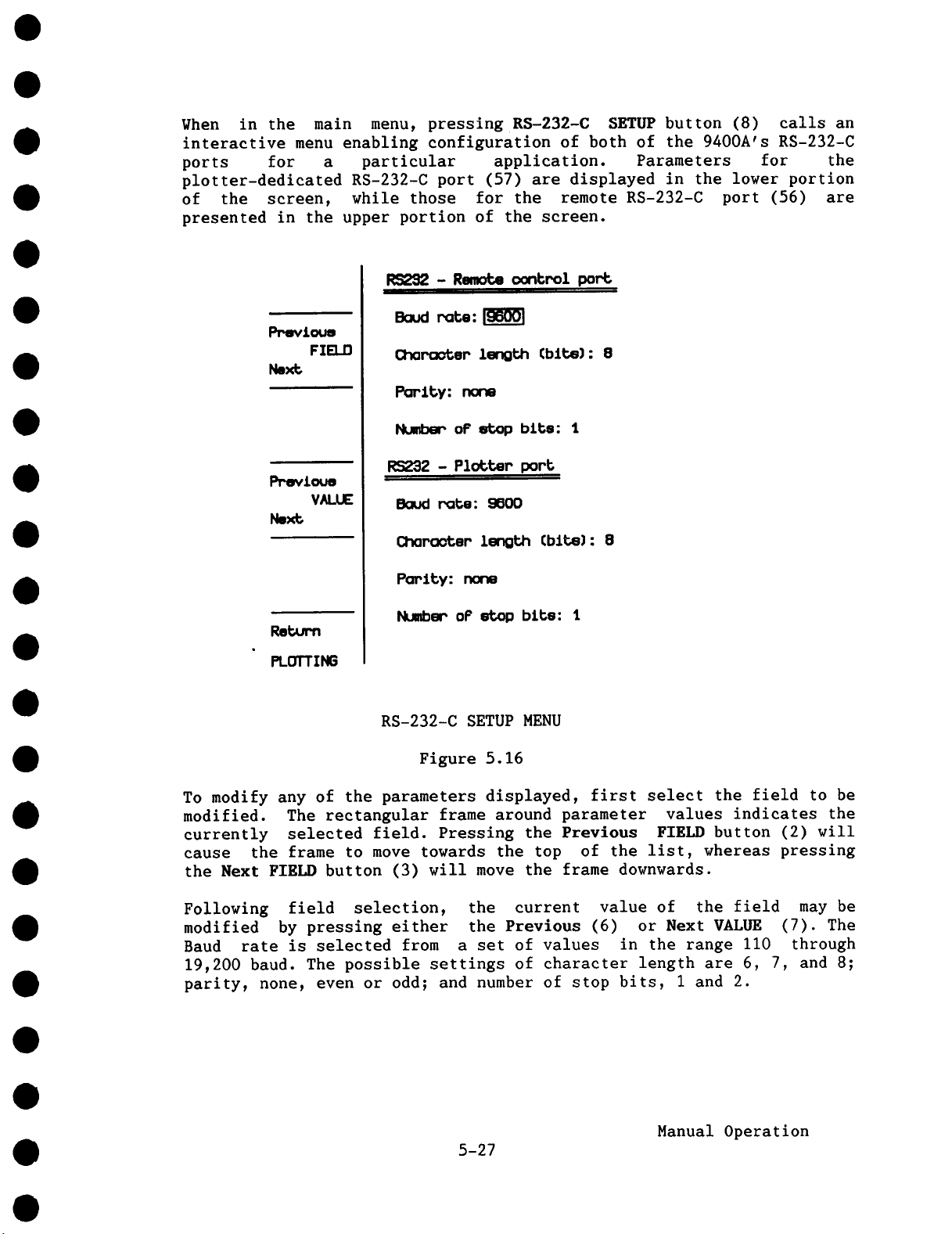
When in the main menu, pressing RS-232-C SETUP button (8) calls
interactive menu enabling configuration of both of the 9400A’s RS-232-C
ports for a particular application. Parameters for the
plotter-dedicated RS-232-C port (57) are displayed in the lower portion
of the screen, while those for the remote RS-232-C port (56) are
presented in the upper portion of the screen.
RS~32 - RemOte c~nbrol port
Saud r’~e: !~
C~ro~er Length Cblt6):
Parity: norm
Number oF stop bits: I
I~wioue
VALUE
Nex~
To modify any of the parameters displayed, first select the field to be
modified. The rectangular frame around parameter values indicates the
currently selected field. Pressing the Previous FIELD button (2) will
cause the frame to move towards the top of the list, whereas pressing
the Next FIELD button (3) will move the frame downwards.
Following field selection, the current value of the field may be
modified by pressing either the Previous (6) or Next VALUE (7).
Baud rate is selected from a set of values in the range ii0 through
19,200 baud. The possible settings of character length are 6, 7, and 8;
parity, none, even or odd; and number of stop bits, I and 2.
RS232 - Plotter port
Baud rate: 9600
Charooter Length Cblt~):
Parity: none
Number oP etop bite: I
RS-232-C SETUP MENU
Figure 5.16
5-27
Manual Operation
Page 70

5.2.7 Plotter Setup (9)
The 9400A has been designed to permit direct interfacing of the
oscilloscope with four of the most popular plotters via the rear panel
RS-232-C dedicated plotter port or the optional GPIB (IEEE-488) port.
When the 9400A is connected to a plotter via the GPIB port, with no
host computer in the configuration, the oscilloscope’s rear panel
thumb-wheel switch must be set to the Talk Only mode (address > 31
decimal) and the plotter to the Listen Only mode.
Plotter setup configuration is similar to configuration of the RS-232-C
ports (see Section 5.2.6 above).
PLOTTER
Plobt~w’: IHE~-ETT PACKARD 7+70A om oompob~hlol
Plobbem pore: RS292
Plob speed: NORHN.
PPovlouo
VALUE
Next;
Reb~Pn
PLOTTING
NuMbem oF Installed pane: Z
PLOT SIZE
Popem eLze: A4 (ISO) - USIt°/8.5"
The plot; amea w111 be 1~ bhon: 22gram ¯ 1BO~
PLOTTER SET-UP MENU
Figure 5.17
5-28
Manual Operation
Page 71
The user can choose the following parameters:
Plotter Type:
Plotter Port:
Plot Speed:
Number of
Installed Pens: I to9
Plot Size:
Non-standard: In the case of non-standard paper sizes, the size of
* If GPIB is selected by no GPIB board is installed (basic 9400A), the
instrument may lock up when the screen dump button is pressed.
HP7470A (or compatible), Philips PM8151
(or compatible),Tektronix or Graphtec FP 5301
RS-232-C or GPIB (IEEE-488)
Normal or Low Speed
ISO A5 (US 8.5" x 5.5"), ISO A4 (US ii"
8.5"),IS0 A3 (US 17" x ii") or non-standard
the grid square can be chosen between 0 to 99.9 mm in
0.I mm steps; lower left corner position from 0 to
999 mm (for both X and Y coordinates) in I mm steps.
5-29
Manual Operation
Page 72

Page 73

SECTION 6
REAR PANEL CONTROLS AND CONNECTORS
6.1
6.2
6.3
Fuse Protection
The power supply of the 9400A is protected against short circuits and
overload by means of a T(slow) 1.6/ 250 V fuse for units which can
operate on 220 V or 115 V mains voltage (switch selected) or a T (slow)
3.15/ 250 V fuse for units operating only on 115 V mains voltage. The
fuse is located under the 115 to 220 V mains voltage selector drum
cover.
Accessory Power Connectors (51)
Two LEMO RA 0304 NYL connectors have been provided to permit use of FET
type probes with the 9400A. These connectors provide output voltages of
+ 5 V, ± 15 V and GND connection, suitable for most FET probes.
The
maximum output current per connector must be limited to 150 mA for
each of the three voltages.
Battery Pack (52)
The battery pack consists of two KR 15/51, 1.2 V rechargeable NiCd
batteries enabling retention of front-panel setups for 6 months in case
of power failure or whenever the 9400A is switched off. The battery
pack is automatically recharged during operation.
6.4
The battery pack can be accessed by pressing the plastic latch at the
top of the cover and pulling it downward and toward the user.
GPIB and RS-232-C Port Selection (54)
The 9400A’s rear panel thumbwheel switch is used to set addresses for
programmed or remote oscilloscope operation. Any one of addresses 31-99
selects the RS-232-C port. Addresses 0-30 define the 9400A’s address
when using the optional GPIB (IEEE-488) port.
GPIB
panel next to each connector.
and RS-232-C pin assignments are clearly indicated on the rear
Rear Panel Controls and Connectors
6-1
Page 74

6.5 Plotter Connector (57)
In addition to the RS-232-C port (56) used for remote 9400A operation,
a second RS-232-C port (57) has been incorporated to facilitate direct
interfacing of the 9400A with a digital plotter. Plotters are used for
hard copy archiving of displayed waveforms and other screen data. Pin
assignments for the plotter connector are identical to those of the
remote RS-232-C port (56).
While a plotter unit connected to the 9400A’s RS-232-C port can be
computer controlled from a host computer via the optional GPIB port,
the oscilloscope’s on-board digital plotter drivers permit hard copies
to be made without an external computer.
Plotter connector pin assignments:
Pin #
2 T x D
3 RxD
4 RTS
5 CTS
20 DTR
6 DSR
1 GND
7 SIG GND
This corresponds to a DTE (Data Terminal Equipment) configuration.
Description
Transmitted Data (from the 9400A)
Received Data (to the 9400A)
Request To Send (always on) (from the 9400A)
Clear To Send (to the 9400A)
When TRUE, the 9400A can transmit.
When FALSE, transmission stops.
Used for 9400A output hardware handshake.
Data Terminal Ready (from the 9400A)
Always TRUE.
Data Set Ready (to the 9400A)
Protective Ground
Signal Ground
6-2
Rear Panel Controls and Connectors
Page 75

SECTION 7
REMOTE OPERATIONS
7.1
Progr.mmed Control
Most of the front panel and internal functions of the 9400A can be
remotely controlled using a set of high-level, English-like commands
and mnemonics. For example, a command followed by <?> tells the scope
to transfer to the host computer the value of the control setting
defined by the command. It is thus possible to read the complete status
of the instrument by repeated queries. It is also possible to save the
entire status of the instrument in binary format with a single command.
The 9400A’s remote control facility allows complex measurement
procedures and instrument setups, a particularly useful feature in
experimental and automated testing environments.
The 9400A can be programmed via the rear panel RS-232-C port interfaced
with a computer terminal or a computer. Remote control is also possible
via GPIB (IEEE-488 bus) if the 9400A has been fitted with the option
OP02. In this case data transfer rates are relatively faster.
To help users who wish to remotely control the Models 9400 (125 MHz
bandwidth) and 9400A (175 MHz bandwidth) oscilloscopes, LeCroy have
published the following application notes which are available on
request:
ITI 002: Linking the LeCroy 9400 to an IBMR PC-AT via the RS-232-C
Asynchronous Interface.
ITI 005: Linking the LeCroy 9400 to an IBM PC-AT via GPIB.
ITI 006: Linking the LeCroy 9400 to an HP 9000 Model 216 controller.
7.2 RS-232-C Ports (56 and 57)
The 9400A has two RS-232-C ports. One is available for computer or
terminal controlled oscilloscope operation, the other for plotter
interfacing. The RS-232-C ports provide an asynchronous data transfer
rate of up to 19,200 baud.
Remote Operations
7-1
Page 76

RS-232-C Pin Assignments
The remote RS-232-C pin Assignments (indicated on the rear panel) are
as follows:
Pin #
2 TxD
RxD
3
RTS
4
5 CTS
2O DTR
DSR
6
GND
1
SIG GND
7
This corresponds to a DTE (Data Terminal Equipment) configuration.
Although descriptions vary slightly, pin assignments for the dedicated
plotter interface (Section 6.6) are identical to those for the remote
RS-232-C connector above.
Description
Transmitted Data (from the 9400A)
Received Data (to the 9400A)
Request To Send (always on) (from the 9400A)
Clear To Send (to the 9400A)
When TRUE, the 9400A can transmit.
When FALSE, transmission stops.
It is used for the 9400A output hardware handshake.
Data terminal ready (from 9400A). If the software
Xon/Xoff handshake is selected it is always TRUE.
Otherwise (hardware handshake) it is TRUE when the
9400A is able to receive characters and FALSE when the
9400A is unable to receive characters.
Data Set Ready (to the 9400A)
Protective Ground
Signal Ground
7.3
GPIB Port (Option OP02 only) (55)
The 9400A’s GPIB interface (optional) complies with IEEE-488 (1978)
standards, and is intended to provide high-speed data transfer in
either the ASCII or binary format between the 9400A and the computer to
which it is interfaced. The maximum data transfer rate, depending on
the controller used, may be as high as 400 kilobytes/sec.
GPIB Port Selection (54)
As mentioned in Section 6.5, the 9400A’s rear panel thumbwheel switch
is used to set addresses for programmed or remote oscilloscope
operation. Addresses 0-30 define the 9400A’s address when using the
GPIB (IEEE-488) port; using any one of addresses 31-99 selects the
RS-232-C port. The thumbwheel is read at power ON only. Whenever the
GPIB address is changed, the power must be turned off and on again.
GPIB functions are clearly indicated on the rear panel next to the GPIB
connector.
Remote Operations
7-2
Page 77

GPIB Functions
The following is a list of the various functions
9400A’s rear panel GPIB connector:
AHI
SHI
L4
T5
SRI
RL2
DCI
DTI
PP1
CO
E2
7.4
7.4.1 Introduction
GPIB and RS-232-C Command Format
All the remote control commands apply equally to communication via the
GPIB and RS-232-C ports. (Note that GPIB commands should not be used
when Option 0P02 is not fitted in the 9400A.) Certain functions,
however, which are part of the GPIB standard (such as Device Clear or
Group Execute Trigger) must be implemented as separate commands for the
RS-232-C interface (see Section 7.6.10). The command syntax
compatible with IEEE Recommended Practice for Code and Format
Conventions (IEEE Standard 728-1982).
provided via the
Complete Acceptor Handshake
Complete Source Handshake
Partial Listener Function
Complete Talker Function
Complete Service Request Function
Partial Remote/Local Function
Complete Device Clear Function
Complete Device Trigger
Parallel Polling: remote configuration
No Controller Functions
Tri-state Drivers
In GPIB, the predefined control commands, such as Device Clear, Group
Execute Trigger, Set Remote or Set Local, are part of the device driver
commands. Therefore the 9400A only has English-like commands for these
functions in RS-232-C inferfacing applications. The user must consult
the manual for his GPIB-interface driver in order to determine the form
of these special commands.
Commands are formed of easy-to-read, unambiguous English words, with
abbreviations (typically 2 to 4 characters) being used to achieve
higher throughput. Short and long formats may be freely substituted for
one another.
The execution of certain commands depends on whether the 9400A is in
the REMOTE or LOCAL state.
Remote Operations
7-3
Page 78

When the 9400A is in LOCAL:
- All the front panel controls are active.
Reading the 9400A by remote control is possible.
-
- The status byte masks (see MASK command) and the communications
protocol (see COMM command) may be written, status bytes may
cleared.
When the 9400A is in REMOTE:
All the front-panel controls are deactivated, except the two
-
display intensity controls and the left-hand side menu buttons.
- All the remote commands are executed.
- A special command (SCREEN) exists to deactivate the front panel
display intensity controls and allows them to be set remotely.
7.4.2 Compound Commands
One or several commands can be sent to the 9400A in a message ending
with <END>. In GPIB transfers, <END> is the line which marks the EOI
(End of Information). In this case, <END> is <;>,<CR> or <LF>.
RS-232-C transfers, <END> is a user-selectable string; the default is
<CR>.
Where multiple commands are used to compose a message, each command is
separated from the following one with a <;>, a <CR> or a <LF> or with
any combination of these characters.
Example:
TRIG SLOPE POS; TIME/DIV 50 NS <END>
represents 2 commands where <;> is used to separate them.
Commands are executed only after <END> is received. Exceptions to this
rule are mentioned later (see Section 7.4.6).
7.4.3 Command Format
Simple commands consist of a header, indicating the desired operation.
The header is usually followed by one or more parameters used to
describe the desired operation in greater detail.
HEADER (<SPACE>, <,> or <=>) Parameter i, Parameter 2, etc.
7-4
Remote Operations
Page 79

The header may be separated from Parameter 1 by either a space, comma,
equals sign or any combination of these. Parameters MUST be separated
from one another using a comma.
Headers and key-word parameters may be transmitted using either the
full or an abridged format. Both upper and lower case characters are
valid and may be used interchangeably.
Numbers must be in accordance with ANSI X3.42-1975 standards and may be
transmitted as integers, or in scientific notation, with or without
exponents. Waveform data values, however, can only be transferred as
integers (8- or 16-bits). Suffixes are optional (but acceptable only
when specifically mentioned).
Example:
The following commands are all legal ways of setting the vertical
gain
of CHANNEL i to I00 mV/div:
CHANNEL 1VOLT/DIV .I
CHANNEL 1VOLT/DIV,IO0 MVOLT
CIVD=IOOE-03 VOLT
CIVD I00 MV
The expression <i00 MV> is considered as a single parameter with a
suffix; therefore no comma is allowed to separate them. The space
separating the parameter value and the suffix is optional.
7.4.4 Answers from the 9400A
As well as specifying a new parameter setting, it is also possible to
query the 9400A in order to obtain a current value. Such queries are
always indicated by a question mark.
Example:
TIME/DIV ?
instructs the 9400A to transmit a character
its current time base value.
Answers from the 9400A are sent in a message followed by
(see COMM TRAILER command) and <END>.
string representing
the TRAILER
7-5
Remote Operations
Page 80

Example:
When set to I00 nsec/div, the answer to the query would be:
TD 100E-09<CR><LF><END>,
where <CR><LF> is the default TRAILER, and
<END> = another <CR>, when using RS-232-C (unless modified with
the command RS CONF).
= EOI-line ACCOMPANYING <LF>, when using GPIB.
If the 9400A generates multiple responses to a single message
containing queries, it will send a separate response for each query.
7.4.5 Flushing of the 94OOA’s Output Buffer
When the 9400A generates an answer to a query or outputs a data stream
in response to a transfer command, the host computer should read the
data. If it fails to do so, the 9400A may become blocked when trying to
output data (this does not occur with a response of less than 80
characters, since the output is buffered).
~henever the 9400A receives a new command message, upon detection of
the <END> of this message, it flushes the output buffer of all
responses due to the previous command message. If the 9400A detects a
new <END> from a new command message while still treating a previous
command message, it aborts those (previous) commands which generate
output data, but not the new commands. The 9400A assumes that the user
is not interested in the answers to previous commands since he is
sending another command message rather than reading the responses.
7.4.6 Command Synchronization with Data Acquisition
Some remote commands cannot be executed at all times, e.g. it is not
possible to read channel 1 or channel 2 while the oscilloscope is armed
and waiting for a trigger, since the memories of the two channels are
continuously being written into.
The user can avoid such situations entirely by only executing
single-shot acquisitions (TRIG MODE SINGLE) and by checking that bit
of status byte 4 (TRIGGERED bit) is set to one (indicating that
acquisition is complete) before sending the READ command.
Another way is to send the command to read channel 1 or channel 2. The
9400A automatically defers the execution of this command until a
waveform has been acquired. It is thus possible to also read waveforms
while the instrument is in the trigger modes NORM or AUTO, i.e.
practically "on-the-fly".
7-6
Remote Operations
Page 81

Execution of the command is also deferred when using some other remote
control commands, in particular the command STORE channel I or
channel 2, and the special command WAlT whose sole purpose is to force
such a synchronization. (See Section 7.6.6 "Other Remote Commands".)
7.4.7 Character Strings
Strings
plotter
command). The string must
default string delimiter
COMM STRDELIM command).
Example:
The TRANSMIT command also outputs
decimal ASCII using a \nnn format.
Example:
If
characters, then <\\> is to be used.
may be displayed (see MESSAGE and KEY commands), sent to
(see the TRANSMIT command) or used as Prompt (see COMM PROMPT
be delimited by string delimiters. The
is <"> and may be changed (see the
COMM STRDELIM 47; MSG /OKAY/
Defines </> (decimal ASCII 47)
display OKAY on the screen.
TRANSMIT "\B27AB"
Can be used to transmit to the plotter the character ESC (decimal
ASCII 27) followed by <A> and <B>.
the backslash character <\> is to be transmitted along with other
as the string delimiter and will
characters that are specified in
Example:
Note:
"\nnn" or "\\" represent only one character of the ASCII string count.
7.4.8 Prompt
The 9400A may generate a PROMPT (see COMM-PROMPT command) when
decodes the <END> message in a command message. This PROMPT will be put
into a message as is done with all other 9400A responses (see Section
7.6.7 7)).
TRANSMIT "AI\\A2"
Instructs the 9400A to transmit the string AI\A2 to the plotter.
Remote Operations
7-7
Page 82

7.4.9 Errors and Adapted Values
When it treats a command, the 9400A checks its validity. The list of
errors is presented in Section 7.6.8 (ERROR status byte).
In general:
A SYNTAX ERROR is produced when the structure of a command is
wrong, or if a command, a key-word parameter or a suffix is not
recognized.
- A SEMANTIC ERROR is produced when the
wrong combination of parameters or if
not valid.
- An ENVIRONMENT ERROR is produced when the command, although it
is valid, cannot be accepted, the 9400A not being in the state
to do so.
When an error is detected, the corresponding code is loaded into status
byte 6, and the bit # 5 of status byte 1 is set.
Some commands cause bit 0 of status byte i (VALUE ADAPTED bit) to
set when the 9400A detects a numerical value or a parameter out of
range. The value is always modified to the closest legal value.
7.5 Data Block Transfers
Data (9400A setup values, waveform values, waveform descriptor) are
transferred between the 9400A and the Host Computer (see the READ or
SETUP commands, Section 7.6.5) or between the Host and the 9400A (see
WRITE
never
separate. This section explains only the overall block structure. For
the interpretation of the data, see Section 7.10.
or SETUP commands) in one or several blocks. Data blocks are
contained within a read or write command, but are always
command is composed of a
a numerical parameter is
Examples:
Reading a waveform from channel i of the 9400A:
- Host sends the command READ,CHANNEL 1.DATA<END> to 9400A.
- 9400A responds with one (or several) data
formats described below, and terminates
<END>.
blocks in one of the
with <TRAILER> and
Remote Operations
7-8
Page 83

Thus, the overall command sequence and data structure is the same
as for queries.
Sending a new setup block to the 9400A:
- Host sends the command SETUP<END> to 9400A.
- Host sends the
composed of a
<END>.
Here, the setup data cannot be directly appended to the setup
command, but must be separated by <END>.
Several block formats are available for read and write; they are
distinguished from each other by the preamble. The command COMM FORMAT
selects the format.
Format A: GPIB only, binary format, no checksum.
Preamble:
Data:
Postscript: None.
Format L: GPIB or RS-232-C, ASCII format.
Preamble: #L<count>, where <count> is
#Abb where bb is the number of data values that will be
sent (2 binary bytes).
One binary byte for each 8-bit value, two binary bytes
for each 16-bit value.
that will be sent.
data blocks to the 9400A. Each data block is
preamble, the data, an optional postscript and
the number of data values
Data: <data>, where <data> are data values in ASCII.
Postscript: None.
<count> and <data> are in the same format but do not necessarily have
the same number of characters. However, <count> is always treated as a
WORD (16 bits), whereas <data> may be chosen as a BYTE (8 bits) or
WORD. The choice of formats (see COMM FORMAT command) is the following:
HEX:
UNSIGNED FIXED:
UNSIGNED SHORT:
BYTE (8 bits value) WORD
xx (2 hex digits) xxxx
nnn (3 decimal digits)
,n (I to 3 decimal digits) ,nnnnn (I to 5 decimal
7-9
nnnnn
(16 bits value)
(4 hex digits)
(5 decimal digits)
digits)
Remote Operations
Page 84

The HEX and UNSIGNED FIXED are fixed size formats, whereas
UNSIGNED SHORT is a variable size format. Therefore, it requires commas
to separate the values.
Examples:
HEX format: #LOOOA0102030405060708090A
UNSIGNED FIXED: #L...I0..I..2..3..4..5..6..7..8..9.10
UNSIGNED SHORT: #L,10,1,2,3,4,5,6,7,8,9,10
Note:
The conversion type and the size must be fixed before reading AND
writing data.
Data transfers via RS-232-C can only be made in ASCII formats.
If the host computer allows only small amounts of data to be sent or
read, the transfer may be partitioned into several blocks of the
selected format. The maximum length of each block is determined by the
COMM BLOCKSIZE command. The length includes all bytes or characters of
the -block as well as characters which may compose the <TRAILER> and
<END>.
Each dot represents a space
character
The transfer will be structured as follows:
st
I
Block -- <TRAILER><END> -- 2
.... -- Last Block -- <TRAILER><END> -- END block -- <TRAILER><END>
Where the END block is:
When reading data from the 9400A, the exact form of
determined by the command COMM TRAILER. <END> is:
<END> = <CR> when using RS-232-C (unless modified with the command
RSCONF).
= EOI ACCOMPANYING the last character of TRAILER, when in GPIB.
If the 9400A receives another command message, terminated with <END>,
while sending data, the transfer is aborted and status byte 6 (ERROR)
is set to the value i.
Data may be lost if the readout sequence is interrupted with a Serial
Poll or by the untalk command.
nd
Block -- <TRAILER><END> -- ....
the TRAILER is
#I
7-10
Remote Operations
Page 85

Thus, the overall command sequence and data structure is the same
as for queries.
Sending a new setup block to the 9400A:
- Host sends the command SETUP<END> to 9400A.
- Host sends the
composed of a
<END>.
Here, the setup data cannot be directly appended to the setup
command, but must be separated by <END>.
Several block formats are available for read and write; they are
distinguished from each other by the preamble. The command COMM FORMAT
selects the format.
Format A: GPIB only, binary format, no checksum.
Preamble:
Data: One binary byte for each 8-bit value, two binary bytes
Postscript: None.
Format L: GPIB or RS-232-C, ASCII format.
Preamble:
#Abb where bb is the number of data values that will be
sent (2 binary bytes).
for each 16-bit value.
#L<count>, where <count> is the number of data values
that will be sent.
data blocks to the 9400A. Each data block is
preamble, the data, an optional postscript and
Data: <data>, where <data> are data values in ASCII.
Postscript: None.
<count> and <data> are in the same format but do not necessarily have
the same number of characters. However, <count> is always treated as a
WORD (16 bits), whereas <data> may be chosen as a BYTE (8 bits) or
WORD. The choice of formats (see COMM FORMAT command) is the following:
WORD
(16 bits value)
(4 hex digits)
(5 decimal digits)
digits)
Remote Operations
HEX:
UNSIGNED FIXED:
UNSIGNED SHORT:
BYTE (8 bits value)
xx (2 hex digits) xxxx
nnn (3 decimal digits) nnnnn
,n (I to 3 decimal digits) ,nnnnn (I to 5 decimal
7-9
Page 86

The HEX and UNSIGNED FIXED are fixed size formats, whereas
UNSIGNED SHORT is a variable size format. Therefore, it requires commas
to separate the values.
Examples:
HEX format: #L000A0102030405060708090A
UNSIGNED FIXED: #L...I0..I..2..3..4..5..6..7..8..9.10
UNSIGNED SHORT: #L,I0,I,293,4,5,6,7,8,9,10
Note:
The conversion type and the size must be fixed before reading
writing data.
Data transfers via RS-232-C can only be made in ASCII formats.
If the host computer allows only small amounts of data to be sent or
read, the transfer may be partitioned into several blocks of the
selected format. The maximum length of each block is determined by the
COMM BLOCKSIZE command. The length includes all bytes or characters of
the -block as well as characters which may compose the <TRAILER> and
<END>.
Each dot represents a space
character
AND
The transfer will be structured as follows:
st
i
Block -- <TRAILER><END> -- 2
.... -- Last Block -- <TRAILER><END> -- END block -- <TRAILER><END>
Where the END block is:
When reading data from the 9400A, the exact form of
determined by the command COMM TRAILER. <END> is:
<END> = <CR> when using RS-232-C (unless modified with the command
RS_CONF).
= EOI ACCOMPANYING the last character of TRAILER, when in GPIB.
If the 9400A receives another command message, terminated with <END>,
while sending data, the transfer is aborted and status byte 6 (ERROR)
is set to the value I.
Data may be lost if the readout sequence is interrupted with a Serial
Poll or by the untalk command.
nd
Block -- <TRAILER><END> -- ....
the TRAILER is
#I
7-10
Remote Operations
Page 87

7.6
7.6.1 Notation
Commands
In this section the following notation is used to explain the commands.
However, these symbols must not be sent to the 9400A as part of a
command.
[ to ]
< >
indicates commands which can be executed in REMOTE only.
Queries (terminated with a <?>) are always allowed.
** indicates commands which can only be executed in REMOTE when
the display intensity controls have also been set to REMOTE.
Example:
TIME/DIV (TD) , < ?
"TIME/DIV" is the long format of the
time base.
denotes the range of a numerical value.
denotes the choice of parameters.
The options are listed vertically.
denotes the abridged format of a keyword.
)
denotes a separator which may be <,> or a space or <=>.
The last two are only acceptable between the header and
the first parameter~ not between parameters.
< [ 2 NS to I00 S ] >
command for controlling the
"TD" is the short form equivalent of
be used at all times.
The comma is the separator between the header and the first
parameter. It may be replaced by a space or by an equal sign <=>,
or by any combination of these. Note that subsequent parameters
MUST be separated from each other by commas only.
The parentheses < > show that the choice of the first (and only)
parameter is either <?> or a time base value in the range of
2 nsec to I00 sec.
The asterisk <*> indicates that this command can only be executed
when the 9400A is in the REMOTE state. However the query
"TIME/DIV 7,,
¯ , can be executed at any time.
7-11
"TIME/DIV". Either form may
Remote Operations
Page 88

7.6.2 Acquisition Parameter Commands
i) TIME/DIV (TD)
Other available suffixes are: US (Bsec, microseconds) and MS (msec,
milliseconds).
The 9400A sets the VALUE ADAPTED bit:
- if an out-of-range value is given.
- if a value outside the incremental steps of i, 2, 5 is given.
Examples:
TD = ?
TD 20 US
TIME/DIV 12 MS
2) INTERLEAVED (IL) , <? >
Enables or disables Interleaved Sampling.
, <? >
< [ 2 NS to I00 S ] >
Instructs the 9400A to send the current time base
value.
Sets the 9400A to 20 Bsec per division.
Sets the 9400A to I0 msec; since the value is
modified from 12 msec to I0 msec, the VALUE ADAPTED
bit in status byte 1 is set.
< ON > *
< OFF > *
The 9400A sets the ENVIRONMENT ERROR:
- if ON command is sent while the time base is greater than 2 US.
- if OFF command is sent while the time base is less than 50 NS.
3) TRIG DELAY (TRD) , < ?
< [ 0.00 % to i00.00 % ] >
<
[ -0.04 NS to -I000000 S ] >
Positive format:
Negative format:
Valid
steps of 1/50 of a division. If the TIME BASE is changed, the
delay remains the same or may change just slightly due to rounding,
provided that it does not exceed I0000 divisions.
Note:
In the case of post-trigger delay, the remote value is negative
while the corresponding value displayed on the screen is positive.
delay v~ues correspond to 0 to i0000 time base divisions in
pre-trigger.
post-trigger delay.
7-12
Remote Operations
Page 89

The 9400A sets the VALUE ADAPTED bit:
- if a positive out-of-range value is given.
- if a negative value corresponding to more than i0000 divisions is
given.
4) TRIG LEVEL (TRL) , < ?
, < [ -5.00 DIV to 5.00 DIV ] >
when the oscilloscope is set to one of the
internal trigger sources (CHANNEL_I or
CHANNEL_2).
, < [ -2.00 V to 2.00 V ] >
when the oscilloscope is set to in the EXT
trigger source.
, < [ -20.0 V to 20.0 V ] >
when the oscilloscope is set to the EXT/10
trigger source.
When the oscilloscope is set to LINE trigger source, this command
has no meaning and no error will be reported. In the case of POS_NEG
triggering, only a positive value is meaningful.
The 9400A sets the VALUE ADAPTED bit:
- if an out-of-range value is given.
The 9400A sets the ENVIRONMENT ERROR:
- if the DIV suffix is sent instead of V or if the V suffix is sent
instead of DIV.
5) TRIG COUPLING (TRC) , < ?
< AC > *
< DC > *
< LF REJ (LF)
< HF-REJ (HF)
6) TRIG MODE (TRM)
The 9400A sets the ENVIRONMENT ERROR:
- if SEQNCE is sent while the 9400A is in Interleaved Sampling.
7) TRIG SOURCE (TRS) , < ?
, < ?
< SEQNCE (SE) > *
< AUTO (AU)
< NORM (NO)
< SINGLE (Sl)
< CHANNEL i (CI)
< CHANNEL-2 (C2)
< LINE (eI)
< EXT (EX)
< EXT/IO (E/IO)
>
>
> *
> *
> *
> *
> *
> *
*
*
*
*
7-13
Remote Operations
Page 90

8) TRIG SLOPE (TRP)
, < ?
< POS (P0)
< NEG (NE)
< POS NEG (PN)
>
>
>
*
*
*
9) SEGMENTS (SEG)
Indicates or selects the number of segments for waveforms acquired
in SEONCE mode.
CHANNEL 1 VOLT/DIV (CIVD)
i0)
CHANNEL 2 VOLT/DIV (C2VD)
The range of the Volts/div setting is limited to 2.5 Volts per
division in the case of 50 Q coupling.
Note that this value corresponds to the 9400A input gain. It does
not take probe attenuation factors into account.
The 9400A sets the VALUE ADAPTED bit:
- if an out-of-range value is given.
Examples:
, <?
<8
< 15
< 31 > *
< 62 > *
< 125 > *
< 250
, <? >
< [ 5.000 MV to 12.500 V ] >
>
>
>
>
*
*
*
CHANNEL_2_VOLT/DIV,500 MV
CIVD=.5
C2VD 120 MV
ii) CHANNEL 1 ATTENUATION (CIAT)
CHANNEL 2 ATTENUATION (C2AT)
Indicates or selects the attenuation factor of the probe.
12) CHANNEL 1 OFFSET (CIOF)
CHANNEL 2 OFFSET (C20F)
The 9400A sets the VALUE ADAPTED bit:
- if an out-of-range value is given.
Sets channel 2 to 500 mV/div
Sets channel 1 to 500 mV/div
Sets channel 2 to 120 mV/div by
choosing I00 mV/div fixed gain and
setting the variable gain to the
required value.
, <? >
< i > *
< I0
< i00 > *
< I000 > *
, <? >
< [ -8.00 DIV to 8.00 DIV ] >
7-14
>
Remote Operations
*
Page 91

13) CHANNEL I COUPLING (CICP)
CHANNEL 2 COUPLING (C2CP)
, <? >
< AC 1 MOHM (AIM)
< DC 1 MOHM (DIM)
< GND
< DC 50 OHM (D50)
> *
> *
>
> *
*
14) BANDWIDTH (BW)
15) STOP
Stops the acquisition of a signal. This command may be used to
return the 9400A from the "armed" state to the "triggered" state,
when the trigger is absent. It generates records similar to those
produced in the AUTO trigger mode.
It is also useful to stop a SEQNCE acquisition when the number of
triggers available is insufficient to fill all sweeps. Upon receipt
of the STOP command, the 9400A displays the artificially completed
sweeps as GND lines.
7.6.3 Display Commands
i) DUAL GRID (DG) , <
- < ON > *
Examples:
, <? >
< ON > *
< OFF > *
< OFF > *
DUAL GRID ON
DG OFF
TRACE CHANNEL I (TRCI)
2)
TRACE-CHANNEL-2 (TRC2)
TRACE-EXPAND A (TREA)
TRACE-EXPAND-B (TREB)
TRACE-MEMORY-C (TRMC)
TRACE-MEMORY-D (TRMD)
TRACE-FUNCTION E (TREE)
TRACE-FUNCTION-E (TREE)
The 9400A sets the ENVIRONMENT ERROR:
- i~h 4 traces are already ON, and a command is received
5
trace ON.
, <?
7-15
Instructs the 9400A to display dual
grids.
Instructs the 9400A to display a
single grid of 8 x i0 squares.
>
< ON > *
< OFF > *
Remote Operations
to turn a
Page 92

Examples:
TRCI ?
TRMC = OFF
3) SELECT (SEL)
Instructs the 9400A to send a message,
indicating whether the display of channel I is
on or off.
Instructs the 9400A to turn the display of
memory C off.
, <? >
< EXPAND A (EA)
< EXPAND-B (EB)
< MEMORY-C (MC)
< MEMORY-D (MD)
< FUNCTION E (FE)
< FUNCTION-F (FF)
> *
> *
> *
> *
> *
>
ii
ii
ii
ii
II
*
Selects a display trace, similar to the front panel control.
Thereafter, the commands VERT GAIN, VERT POSITION, TIME_MAGNIFIER,
HOR POSITION and REDEFINE will-be applied to the SELECTed trace.
The 9400A sets the ENVIRONMENT ERROR:
- if the SELECTed trace is OFF.
4) VERT GAIN (VG) , < ?
-
VERT GAIN is applied to the SELECTed trace. This command instructs
the 9400A to modify the display gain (not the acquisition gain) by
factor of up to 2.5.
< [ 1.000 to 2.500 ] >
>
II
II
II
I
II
II
II
7-16
Remote Operations
Page 93

Adj us tment
Manually appears in the window* on value in the window*
Reduce Signal Size
Turn the Vert. Gain knob Turn the Vert. Gain knob
anti-clockwise. clockwise.
Notice that a ">" symbol Notice that the volts
9400A screen. changes, e.g. ".5 V"
Increase Signal Size
changes to "> .2 V"
Read the exact V/div in
the memory STATUS menu. the memory STATUS menu.
Enter the command "VG ?"
Query
The response is a value between i and 2.5.
Exact V/div = response x value indicated in the
select window on 9400A screen.
I
Remote
Control value between I and 2.5
* assumes that cursors are not being used
Enter "VG" followed by a
to attenuate the signal
up to 2.5 times.
I
Read the exact V/div in
Not possible
The 9400A sets the VALUE ADAPTED bit:
- if an out-of-range value is given.
The 9400A sets the ENVIRONMENT ERROR:
- if the SELECTed trace is OFF.
5) VERT POSITION (VP) ,
VERT POSITION is applied to the SELECTed trace. This command
instructs the 9400A to modify the display position (not the
acquisition offset) of the selected trace by up to ± 16 divisions,
relative to the original position at acquisition.
<? >
< [ -16.00 DIV to 16.00 DIV ] >
Remote Operations
7-17
Page 94

The 9400A sets the VALUE ADAPTED bit:
- if an out-of-range value is given.
The 9400A sets the ENVIRONMENT ERROR:
- If the SELECTed trace is OFF.
6) TIME MAGNIFIER (TM) , < ?
< [ 0 to6 ] >
TIME MAGNIFIER is applied to the SELECTed trace. It may only be
applTed to traces EXPAND A or EXPAND B.
The value 0 corresponds to no expansion. Each increment of I
corresponds to the next lower time base value (relative to the
original trace). The value 6 therefore allows an expansion by
factor of I00.
The 9400A sets the VALUE ADAPTED bit:
- if an out-of-range positive value
generate a semantic error.
The 9400A sets the ENVIRONMENT ERROR:
- if the SELECTed trace is OFF.
- if the SELECTed trace is neither EXPAND A nor EXPAND B.
7) HOR POSITION (HP) , <
, < [ 0.0000 DIV to i0.0000 DIV ] >
when the source trace corresponds to a single
waveform (acquired in single shot or with
INTERLEAVED ON).
, < [ 1 to max ] >
when the source trace corresponds to multiple
waveforms (acquired in SEQNCE).
The parameter indicates the number of the
sequence to be displayed. "max" depends on the
selected number of segments (see SEGMENTS).
HOR POSITION will be applied to the SELECTed trace. It may only be
applied to traces EXPAND A or EXPAND B. The parameter in the range
0 to I0 divisions corresponds to The CENTER of the intensified
region on the original trace. The smallest possible step is
0.0004 div.
is given. Negative values
>
The 9400A sets the VALUE ADAPTED bit:
- if an out-of-range value is given (Interleaved Sampling or Single
Shot).
- if a positive out-of-range value is given (SEQNCE). Negative
zero values generate a semantic error.
Remote Operations
7-18
Page 95

The 9400A sets the ENVIRONMENT ERROR:
- if the SELECTed trace is OFF.
- if the SELECTed trace is neither EXPAND A nor EXPAND B.
8) REDEFINE (RDF)
Redefines the source of the SELECTed trace to
CHANNEL 2, MEMORY_C,
EXPAND A or EXPAND B.
The 9400A sets the ENVIRONMENT ERROR:
- if the SELECTed trace is OFF.
- if the SELECTed trace is neither EXPAND A nor EXPAND B.
9) MESSAGE (MSG)
The string may be up to 43 characters in length. The message is
displayed in
Section 4.6).
Example:
MESSAGE "Apply probe to Jll.5, then press READY"
, < ?
< CHANNEL I (Cl)
< CHANNEL-2 (C2) > *
< MEMORY C (MC) > *
< MEMORY-D (MD)
or MEMORY_D. The SELECTed
, <String to be displayed>
the Message Field above the graticule (see
>
>
> *
be CHANNEL i,
trace must be
*
Instructs the 9400A to display the message between the
string delimiters " on the line above the graticule.
The push button READY does not exist on the 9400A, but any
of 9 soft keys may be defined as such with the command KEY.
i0) KEY , < [I to 9] > , <String to be displayed>
The string is displayed in the Menu Field (see Section 4.1) next
the soft key selected with the first parameter. The string may be up
to Ii characters in length.
Examples:
KEY 3,!READY!
Instructs the 9400A to display the message "READY" next to
the third (from the top) soft key on the left hand side
the graticule. This command is only accepted if the string
delimiter has been changed from the default value <"> to
<!> with the command COMM STRDELIM=33. The default value
<"> = 34 (see Section 7.6.7).
7-19
Remote Operations
Page 96

KEY l, "Restart"
Instructs the 9400A to display the message "Restart" next
to the first soft key. Here, the default string delimiter
is used.
11) SCREEN (SCR)
, <? >
< REMOTE (RM) *
< LOCAL (LC) *
or
SCREEN (SCR) , < ON **
< OFF > **
or
SCREEN (SCR) , < INTENSITY (INT) > , [0 to
< GRID INTENSITY (GI)>
"?" allows the user to know the status of the screen.
"REMOTE" and "LOCAL" select the control mode of the screen.
When the 9400A is set to REMOTE, the screen remains under LOCAL
control allowing the operator to adjust the display intensity. The
screen itself must be put into the REMOTE state using the command
SCREEN (SCR) , <ON> before the commands marked with "**" are valid.
"ON" and "OFF" turn the screen ON an OFF respectively.
When the 9400A is being used to capture transients automatically
without a user looking at the display, the display may be turned
off. This improves the response time of the instrument since display
generation, which may take up to I00 msec, is suppressed.
**
**
"INTENS" and "GRID INT" set the display intensity.
The 9400A sets the VALUE ADAPTED bit:
- if a value greater than 170 is given.
7.6.4 Plotter Commands
i) PLOTTER (PT)
or
PLOTTER (PT)
, <? >
, <name> , <port> , <speed> , <pens>
Remote Operations
7-20
Page 97

<name> = < GRAPHTEC (GR) >
< HEWLETT PACKARD (HP) >
<
PHILIPS (PH)
<
TEKTRONIX (TEK)
>
>
<port> = < RS232 (RS)
< GPIB (SP)
<speed> < NORMAL SPEED (NS)
< LOW SPEED (LS)
<pens> = [ 1 to 9 ]
Configures the 9400A for a predefined plotter.
Examples:
PLOTTER HP,RS,NS,2
Configures the 9400A for a Hewlett-Packard plotter,
connected to the RS-232-C plotter port, running at normal
speed, with 2 pens. This is how the 9400A must be
configured for the HP7470 and HP7475 or compatible
plotters.
PT,GR,GP,LS,4
Configures the 9400A for a Graphtec FP5301 or compatible
plotter, connected through GPIB, running at low speed (for
plotting on transparencies), with 4 pens.
2) PLOT SIZE (PS) , <? >
< A5 > *
< A4 > *
< A3 > *
Configures the 9400A to plot onto a predefined paper size.
AS=
A4=
A3 =
or
148 mm by 210 mm, compatible with U.S. 5 1/2" by 8 1/2"
210 mm by 297 mm, compatible with U.S. 8 1/2" by II"
297 mm by 420 mm, compatible with U.S. ii" by 17"
PLOT SIZE (PS) , NON STANDARD (NSTD) , <grid> , <x> ,
Configures the 9400A to plot onto a non-standard paper size.
<grid> = [ 00.0 MM to 99.9 MM ]
7-21
Remote Operations
Page 98

<x> = [ 0 MM to 999 MM ]
<y> [ 0 MM to 999 MM ]
<grid> is the size (length of a side) of the standard square
within the 8 times I0 squares grid.
<x>,<y> are the positions of the lower left hand corner of the
graticule with respect to the origin of the plotter.
The 9400A sets the VALUE ADAPTED bit:
- if an out-of-range positive value
generate a semantic error.
3) SCREEN DUMP (SD)
Instructs the 9400A to dump the screen display onto the plotter.
4) TRANSMIT (TX) , <String to be transmitted to the plotter>
Instructs the 9400A to transmit a character string to the plotter.
The string may be up to 43 characters in length and may include
commands such as "paper advance" or "print string". This enables the
user to add comments to a plot, or generate multiple plots by remote
control.
The 9400A sets the ENVIRONMENT ERROR:
- if the 9400A is controlled through GPIB and if the plotter access
port is the GPIB port.
7.6.5 Transfer Comm~,ds
i) STORE (STO) , [ 1 to
is given. Negative values
*
instructs the 9400A to store the current front panel configuration
in one of 7 non-volatile storage areas for later recall.
or
STORE (STO)
, < CHANNEL 1 (CI) > , < MEMORY C (MC)
< CHANNEL-2 (C2) > < MEMORY-D (MD)
instructs the 9400A to store the waveform and the waveform
descriptor of either Channel 1 or 2 into reference memories C or D.
Notes:
If the 9400A receives a command to store Channel 1 or 2 while it is
acquiring data, the execution of the command is delayed until the
trigger has arrived.
Remote Operations
7-22
Page 99

No message will be displayed on the screen when the operation is
performed.
2) RECALL (REC) , [ 1 to
instructs the 9400A to recall one of 8 front-panel configurations
stored in non-volatile memory. The value "8" corresponds to the
default setup.
3) SETUP (SU)
or
SETUP (SU) *
The first form permits the complete setup to be read in internal
data representation. Transmission format depends on the selected
forms by the COMM FORMAT command. The setup data block corresponds
to 257 binary bytes.
The second form permits setup data to be sent to the 9400A in the
same form as they were read from the 9400A. This command must be
terminated with <END>, i.e. it must be the last of a list of
commands. The data transferred to the 9400A must be contained in a
separate block (see Section 7.5).
Note:
The serial port parameters can not be transmitted. In particular, if
the transfers are by RS-232-C, modification of the serial port
parameters by this command would bring about some strange results.
The 9400A sets the VALUE ADAPTED bit:
- if a data value in the block is incorrect. The DEFAULT setup will
be used in this case.
The 9400A sets the INVALID BLOCK ERROR:
- if the received block(s) is incorrect.
4) READ (RD)
, < CHANNEL I.DESC
< CHANNEL-2.DESC
< MEMORY C.DESC
< MEMORY D.DESC
(CI.DE)
(C2.DE)
(MC.DE)
(MD.DE)
transfer the descriptor of the indicated waveform from the 9400A to
the host computer. See Section 7.7 for the format of this data
block.
or
7-23
Remote Operations
Page 100

READ (RD)
, < CHANNEL 1.DATA
< CHANNEL 2.DATA
< MEMORY C.DATA
< MEMORY-D.DATA
(CI.DA) > , <Parameter list>
(C2.DA) >
(MC.DA)
(MD.DA)
<Parameter list> = <intval> , <# values> , <addr> , <sweep #>
transfer the data values of the indicated waveform from the 9400A to
the host computer. An explanation of the optional parameter list is
given below.
or
READ (RD) , < CHANNEL 1.TIME
< CHANNEL-2.TIME
< MEMORY C.TIME
< MEMORY-D.TIME
(CI.TI)
(C2.TI)
(MC.TI)
(MD.TI)
transfer the trigger time(s) of the indicated waveform from the
9400A to the host computer. See Section 7.8 for the format of this
data block.
or
READ (RD) , < CHANNEL I.* (CI.*) > , <Parameter list>
<
CHANNEL-2.* (C2.*)
< MEMORY C.* (MC.*)
< MEMORY-D.* (MD.*)
transfer ALL visible data of the indicated waveform from the 9400A
to the host computer. Data are transferred in the order descriptor,
data, time(s).
<Parameter list> = <intval> , <# values> , <addr> , <sweep #>
<intval> = [ 1 to 16000 ]
Interval between data points to be
read, for example:
I = read all points
4 = leave out 3 of 4 data values
<# values>= [ 0 to 32000 ]
<addr> = [ -32000 to 32000 ]
Number of data values to read
Address of first data
relative to the left hand
the screen
<sweep #> = [ 0 to 250 ] Sweep number in SEQNCE
numbered from
1 to max. # sweeps
0 = read all sweeps
Remote Operations
7-24
point
side of
waveforms,
 Loading...