

Page 1
7,0(%$6(75,**(5
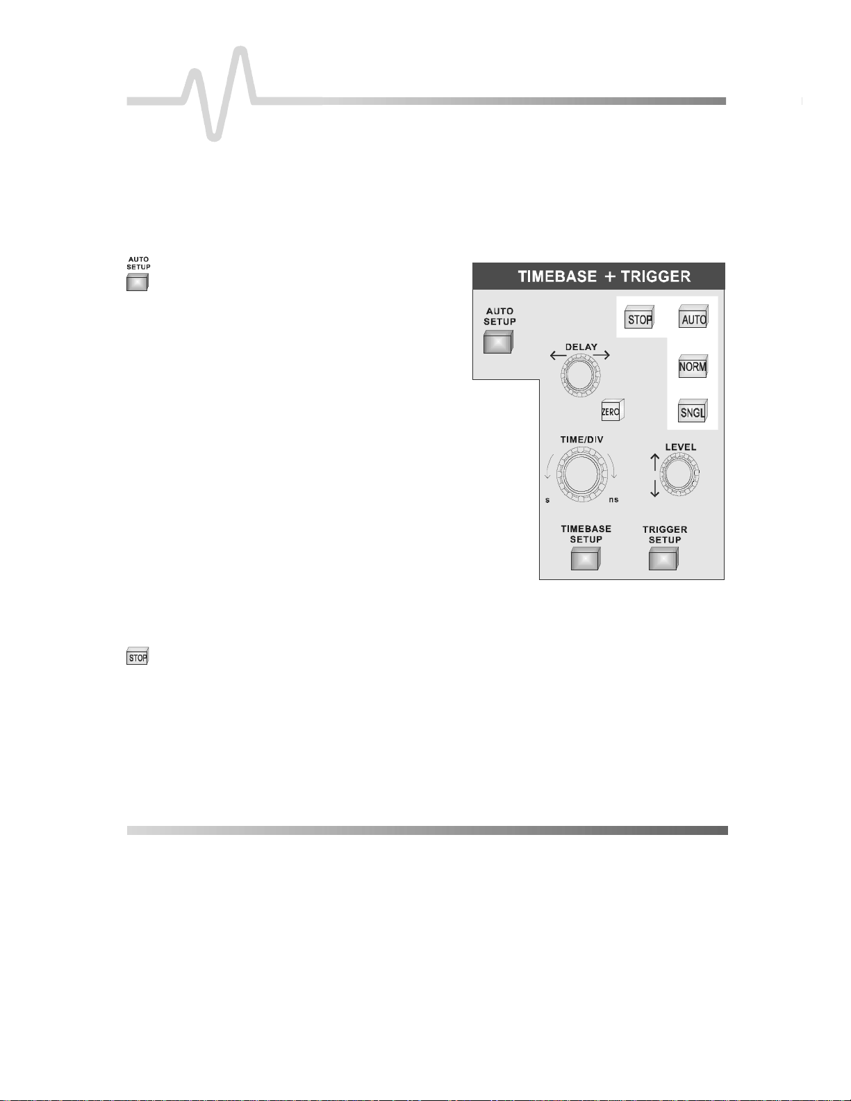
7,0(%$6(75,**(5&RQWUROV
These controls allow direct adjustment of time/division,
trigger level and delay, and access the “TIMEBASE” and
“TRIGGER” menu groups.
$8726(783 The blue button
automatically scales
the timebase, trigger
level, offset, and
volts/div to provide a
stable display of
repetitive signals.
AUTO SETUP operates only on
channels which are active. If no
channels are on, then AUTO
SETUP will operate on all
channels, switching them all on.
Signals detected must have an
amplitude between 5 mV and
40 V, a frequency greater than
50 Hz, and a duty cycle greater
than 0.1 %.
If signals are detected on several
channels, the channel with the lowest number will determine the
selection of the timebase and trigger source.
6723 This button halts the acquisition in any of the three
modes: Auto, Normal or Single.
Pressing the STOP button prevents the oscilloscope ac quiring a
new signal.
Press STOP while a single-shot (
under way and the last acquired signal will be kept.
²
see next chapter
) acquisition is
re-arming
Page 2

7,0(%$6(75,**(5
Press STOP after an RIS acquisition has been started (
chapter
reconstruction will be performed.
Press STOP when the acquisition is in Roll Mode (
chapter
trigger had occurred.
In Sequence Mode (
timebase and show all new segments.
$872 Pressing this button places the instrument in Auto Mode: the
scope automatically displays the signal if
60 ms.
If a trigger does occur within this time, the osc illoscope behaves
as in Normal Mode.
Press AUTO in RIS Mode and the ac quisition will be terminated
and shown each second (some required segments may be
missing).
Press the button in Roll Mode and the oscilloscope will sample
the input signals continuously and indefinitely. The acquisition will
have no trigger condition but can be stopped as desired.
Press AUTO in Sequence Mode and the acquisition will be
terminated if the tim e between two consecutive triggers exceeds
a timeout that can be selected. The next acquisition is then
started from Segment 1.
) and the acquisition will be halted and a partial waveform
) and the incomplete acquisition data will be s hown as if a
next chapter
), the action will stop the
no
trigger occurs within
next
see next
1250 Pressing this button will continuously update the screen as long
as a valid trigger is present. If not, the last signal is preserved
and the warning “SLOW TRIGGER” is displayed in the Trigger
Status Field.
Press NORM in Roll Mode and the acquisition will be terminated
when the last needed data after a trigger have been taken. The
display will pause to show the entire waveform. It then goes back
into Roll Mode while it waits for the next trigger.
Press this button in Sequence Mode and the acquisition will be
terminated after the last segment is acquired. The next
acquisition will start imm ediately. Sequence WRAP in Norm al is
the same as in Single-Shot Mode.
²
Page 3

61*/ Pressing this button places the scope in Single-Shot Mode,
where it waits for a single trigger to occur, then displays the
signal and stops acquiring. If no signal occurs, the button can be
pressed again to show the signal being observed without a
trigger.
Press SNGL when in RIS Mode and the instrum ent will wait for
all the trigger events required to build up one signal on screen
before it stops. This may require as many as 4000 trigger events.
Single-Shot Roll Mode behavior is the same as standard SingleShot but without the need to press the button a second time to
show the signal.
'(/$< — is used to adjust the pre- or post-trigger delay. Pre-trigger
adjustment is available from zero to 100 % of the full tim e-scale
in steps of 1 %. The pr e-trigger delay is illustrated by the vertical
arrow symbol at the bottom of the grid. Post-trigger adj ustm ent is
available from 0 to 10 000 divisions in increments of 0.1 of a
division. The post-trigger-delay value is labeled in se conds and is
located in the on-screen Trigger Delay field.
=(52 — sets the trigger delay at zero, the trigger instant at the left-
hand edge of the grid.
7,0(',9 — selects the time per division in a 1–2–5 sequence. The
time/div setting is displayed in the Acquisition Summary field.
/(9(/ — adjusts the trigger threshold. T he amplitude of trigger signals
and the range of trigger levels is lim ited: ± 5 screen divisions with
a channel as trigger source; ± 0.5 V with EXT as trigger source;
5 V with EXT/10 as trigger source; and Inactive with Line as
trigger source. The trigger sensitivity is better than a third-of-ascreen division.
²
±
Page 4

7,0(%$6(75,**(5
7,0(%$6(6(783 — menu-entry button that calls up the “TIMEBASE” menus
described in the next chapter
.
75,**(56(783 — menu-entry button that calls up “TRIGGER SETUP”
in Chapter 8
.
detailed
²
 Loading...