

Page 1
Operator’s Manual
Model 9210
300 MHz
Programmable
Pulse Generator
March
1, 1995
Rev. B
Page 2
LeCroy
Innovators in Instrumentation
Corporate Headquarters
700 Chestnut Ridge Road
Chestnut Ridge, NY 10977-6499
Tel: (914) 578-6020, Fax: (914) 589-5985
European Headquarters
2, chemin-Pre-de-la Fontaine
1217 Meyrin 1
Geneva, Switzerland
Tel.: (022) 719 21
Copyright© March 1, 1995, LeCroy. All fights
reserved. Information in this publication supersedes
all earlier versions. Specifications subject to change
without notice.
Page 3
TABLE OF CONTENTS
9210 QUICK START ...................................................................................................
Purpose .......................................................................................................................1
Quick Start Instructions ................................................................................................
GE’I-I’ING AROUND THE FRONT PANEL ................................................................. 5
Accessing the Control Displays ..................................................................................... 5
Selection of Parameters .............................................................................................. 6
Adjusting Parameters with the Numeric Keypad .........................................................
Adjusting Parameters with the Rotary Knob ................................................................
Non-Numeric Entries ...................................................................................................
Storing & Recalling Setups .......................................................................................... 8
Executing Action Commands .......................................................................................
Manually Triggering the Generator ............................................................................
Alternate Parameter Formats ....................................................................................
Restoring Local Control ............................................................................................. 11
Module Controls - Enabling or Inverting the Pulse Output .........................................
Power - Turning the Generator On & Off .................................................................. 13
3
CHANNEL A & B CONTROLS ................................................................................. 15
General Information ...................................................................................................15
Controlling Vertical Characteristics ............................................................................
Width - Controlling Horizontal Duration ....................................................................
Delay - Controlling Horizontal Position ...................................................................... 20
Controlling Transition Rates ...................................................................................... 21
Dynamic Range and Transition Rates ....................................................................... 24
Double Pulse Operation ............................................................................................. 25
Controlling Repetition Rate ........................................................................................ 26
Parameter Conflicts ...................................................................................................27
Load Compensation ...................................................................................................
Logic Family Presets .................................................................................................
Limiting the Output Levels ................................................................................... ......32
Module Considerations ..............................................................................................
1
1
7
7
8
9
11
11
12
15
17
30
32
32
4
TRIGGER CONTROLS ............................................................................................. 39
General Information ...................................................................................................39
The Trigger Output ....................................................................................................
The Trigger Input .......................................................................................................
Frequency Counter ....................................................................................................
39
39
40
Page 4

Table of Contents
’ ........
41
41
42
43
44
46
47
47
47
47
47
48
48
48
49
49
49
50
51
51
53
53
55
56
57
57
58
58
59
59
59
Trigger Modes ...........................................................................................................
Normal Mode .....................................................................................................
Single Mode ..............................................................................................................
Gate Mode ................................................................................................................
Burst Mode ................................................................................................................
External Width Mode .................................................................................................
Double Pulse Interactions .........................................................................................
Normal Mode .............................................................................................................
Single Mode ..............................................................................................................
Gate Mode ................................................................................................................
Burst Mode ................................................................................................................
External Width Mode .................................................................................................
Setting the Trigger Level and Slope ..........................................................................
Setting the Trigger Level Automatically .....................................................................
Parameter Limits and Triggering ...............................................................................
Setting the Internal Trigger Rate ...............................................................................
Using The Manual Trigger Button .............................................................................
Adjusting the Trigger Output Offset ...........................................................................
Selecting the Trigger Input Impedance .....................................................................
Trigger Output Presets ..............................................................................................
5
THE "MORE" MENU - UTILITIES AND FEATURES ...............................................
Invoking Self-Calibration ...........................................................................................
Invoking Selftest ........................................................................................................
Calibration and Selftest Results ................................................................................
Monitoring the GPIB Interface ...................................................................................
Testing the User Interface .........................................................................................
The Configuration Menu ............................................................................................
The Screen Saver .....................................................................................................
Disabling the Touch Screen ......................................................
Display Brightness .....................................................................................................
Temperature Compensation .....................................................................................
: ...............................
6
REMOTE OPERATIONS ..........................................................................................
General Information ..................................................................................................
Terminology ..............................................................................................................
Numeric Representation ...........................................................................................
Header Compounding ...............................................................................................
Coupled Commands .................................................................................................
Responses ................................................................................................................
Status Reporting .......................................................................................................
Common Commands ................................................................................................
61
61
61
61
62
62
62
63
63
Page 5
Table of Contents
GPIB COMMANDS ...................................................................................................
General Information ...................................................................................................
Commands Which Correspond To Local Controls ....................................................
*CAL ............................................................................................................
*RCL ............................................................................................................
*SAV ............................................................................................................
*TRG ...........................................................................................................
*TST ............................................................................................................
AMP ............................................................................................................
AUTOL ........................................................................................................
BASE ...........................................................................................................
BC ...............................................................................................................
BRI ..............................................................................................................
DBL .............................................................................................................
DEL .............................................................................................................
DISA ............................................................................................................
DISP ............................................................................................................
DUTY ..........................................................................................................
FREQ ..........................................................................................................
INV ..............................................................................................................
LEAD ...........................................................................................................
LIM ......................................................................................
LVH .............................................................................................................
LVL ..............................................................................................................
LOADC ........................................................................................................
MED ............................................................................................................
OUT .............................................................................................................
OUTBar .......................................................................................................
PER .............................................................................................................
PHA .............................................................................................................
SCRNSAVE ................................................................................................
SLEW_L ......................................................................................................
SLEW_T ....................................................................
TEMPC ........................................................................................................
TOUCH .......................................................................................................
TRAIL ..........................................................................................................
TRIM ...........................................................................................................
TRLV ...........................................................................................................
TRMD ..........................................................................................................
TROV ..........................................................................................................
TROV_SET .................................................................................................
TRSL ...........................................................................................................
i .......................75
: .................................
65
65
66
66
67
67
67
68
68
69
69
70
70
71
71
72
72
73
73
74
74
75
76
77
78
79
79
80
80
81
81
82
83
83
84
84
85
85
86
86
87
iii
Page 6
Table of Contents
VHI ..............................................................................................................
VLO .............................................................................................................88
VSET ..........................................................................................................89
WlD .............................................................................................................
Commands Which Have No Corresponding Local Controls .....................................
*CLS .............................................................................................................
*ESE .............................................................................................................
*ESR ............................................................................................................
*IDN ...............................................................................................................
*LRN .............................................................................................................
*OPC ............................................................................................................
*OPT ............................................................................................................
*RST .............................................................................................................
*SRE ............................................................................................................
*STB .............................................................................................................
*WAI .............................................................................................................
CHDR ...........................................................................................................
CHK ..............................................................................................................
DEGC_CHG .................................................................................................
ERR ..............................................................................................................
MSG .............................................................................................................
TER ...............................................................................................................
APPENDIX A Specifications ................................................................................
LeCroy 9210 300 MHz Programmable Pulse Generator Mainframe ........................
LeCroy 9211 250 MHz, Variable Edge Output Module ...........................................
LeCroy 9212 300 MHz, 300 psec, Variable Edge Output Module ...........................
LeCroy 9213 50 MHz, 16V Amplitude Output Module ............................................
LeCroy 9214 300 MHz, 300 psec, Fixed Edge Output Module ...............................
87
89
90
90
90
91
91
91
92
93
93
94
94
95
95
96
96
97
97
98
99
99
105
109
113
116
APPENDIX B Warranty .......................................................................................
Unpacking and Inspection ......................................................................................
Warranty ..................................................................................................................
Calibration ...............................................................................................................
Documentation Discrepancies .................................................................................
APPENDIX C
iv
Service ...........................................................................................
119
119
119
120
120
121
Page 7

Table of Contents
APPENDIX D GPIB Documentation ...................................................................
General Information ..................................................................................................
GPIB Interface Function Subsets .............................................................................
Addressing Information .............................................................................................
Restoration of Settings .............................................................................................
Commands and Queries ...........................................................................................
Device Specific Commands ......................................................................................
Data Elements ..........................................................................................................
Query Responses .....................................................................................................
Implemented Commands and Queries .....................................................................
State After Calibration ...............................................................................................
Identification Response ............................................................................................
Reset, Save, Recall and Learn ................................................................. ................
Selftest ......................................................................................................................
Status Data Structure ...............................................................................................
Sequential Processing ..............................................................................................
Operation Complete ........................................................................... : ......................
Additional Notes ........................................................................................................
APPENDIX E
Error Messages ............................................................................. 141
GPIB Error Queue ...................................................................................................
Command Errors ......................................................................................................
Execution Errors .......................................................................................................
Query Errors .............................................................................................................
Device Specific Errors ..............................................................................................
Displayed Error Messages ........................................................................................
123
123
123
124
124
124
126
126
127
127
127
128
128
129
136
139
139
140
~ 141
142
146
147
148
151
APPENDIX F
Ampl ..........................................................................................................................
Base ..........................................................................................................................
Burst Mode ...............................................................................................................
Delay .........................................................................................................................
Double Pulse ............................................................................................................
Duty Cycle ................................................................................................................
External Width Mode ................................................................................................
Frequency .................................................................................................................
Gate Mode ................................................................................................................
Lead ..........................................................................................................................
Load Compensation ..................................................................................................
Glossary ....................
~ ...................................................................
159
159
159
159
161
162
162
163
163
164
164
165
V
Page 8
Table of Contents
Median ......................................................................................................................
Normal Mode .............................................................................................................
Period ........................................................................................................................
Phase ........................................................................................................................
Single Mode ..............................................................................................................
Slew ..........................................................................................................................
Temperature Compensation .....................................................................................
Trail ...........................................................................................................................
Trigger Level .............................................................................................................
Trigger Slope .............................................................................................................
Trigger Output Level .................................................................................................
Vhigh .........................................................................................................................
Vlow ..........................................................................................................................
Width .........................................................................................................................
Appendix G 9210 Pulse Generator Manual Addenda ......................................................
Important Notice ........................................................................................................
For Mainframe Firmware Versions 2.7 and up ..........................................................
For 9212 users with Module Firmware Versions 1.6 and up ..................................... 172
Firmware Versions 2,8 and up ..................................................................................
Changes and additions to 9112 Output Module Specifications .................................
Additional Feature for the 9212 Output Module ........................................................
Appendix H 9210-50/250 100 MHz Pulse Generator Mainframe Specifications .............
Important Notice ........................................................................................................
Timing Characteristics ............................................................................................... 175
Inputs and Outputs ....................................................................................................
Programmability ........................................................................................................
Triggering Modes ......................................................................................................
Operating Features ...................................................................................................
Additional Capabilities ...............................................................................................
Environmental ...........................................................................................................
Power ........................................................................................................................179
Miscellaneous ............................................................................................................
165
165
166
167
167
168
168
168
169
169
169
169
169
170
171
171
171
172
172
173
175
175
176
177
178
178
179
179
180
Appendix 1 9215 50 MHz, 15V Amplitude Output Module Specifications .......................
Timing Characteristics ...............................................................................................
Pulse Performance ....................................................................................................
vi
181
181
182
Page 9
Table of Contents
Appendix J 9211MOD100 100 MHz Output Module Specifications ..........................
Timing Characteristics ........................................................................................
Output Characteristics ........................................................................................
Output Levels ......................................................................................................
Pulse Performance .............................................................................................
Module Controls ..................................................................................................
INDEX 189
185
185
185
185
187
188
vii
Page 10
1 9210 QUICK START
Purpose
Quick Start
Instructions
The intent of this chapter is to familiarize the first-time user
of the LeCroy 9210 Pulse Generator with the instrument’s
uniquely user-friendly control scheme. The information
presented herein is intended to "get you up to speed" in as
short a time as possible. Detailed answers to specific
questions that may arise will be found in other chapters.
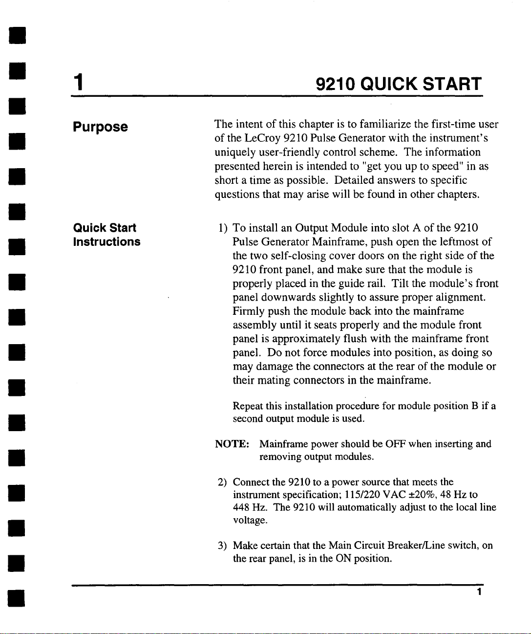
1) To install an Output Module into slot A of the 9210
Pulse Generator Mainframe, push open the leftmost of
the two self-closing cover doors on the right side of the
9210 front panel, and make sure that the module is
properly placed in the guide rail. Tilt the module’s front
panel downwards slightly to assure proper alignment.
Firmly push the module back into the mainframe
assembly until it seats properly and the module front
panel is approximately flush with the mainframe front
panel. Do not force modules into position, as doing so
may damage the connectors at the rear of the module or
their mating connectors in the mainframe.
Repeat this installation procedure for module position B if a
second output module is used.
NOTE: Mainframe power should be OFF when inserting and
removing output modules.
Connect the 9210 to a power source that meets the
2)
instrument specification; 115/220 VAC __.20%, 48 Hz to
448 Hz. The 9210 will automatically adjust to the local line
voltage.
3) Make certain that the Main Circuit Breaker/Line switch, on
the rear panel, is in the ON position.
Page 11
1
9210 Quick Start
I/
Vlow
[ Width I’" 2.00ns
I Delay I’" 2.00ns
I Lead -J’l’" 1.00ns
I Trail "L I-. 1.00ns
12 Pulse I" .....
Main
Period
I
[" 10.00ns
OFF
I No,m°, I sO I
SELECT
DiS
I
t ........
J~[-- ~’~’.),nput ~ output Pu.sE~-~,E,,ro, 9210 J~\
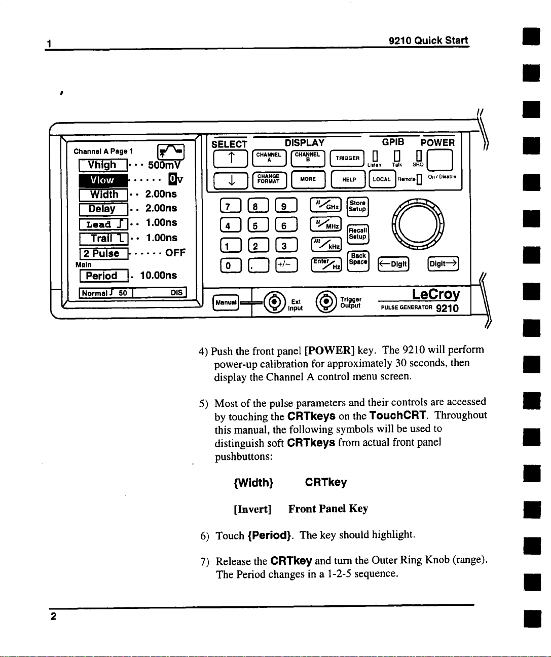
4) Push the front panel [POWER] key. The 9210 will perform
power-up calibration for approximately 30 seconds, then
display the Channel A control menu screen.
DISPLAY GPIB POWER N--l/
5) Most of the pulse parameters and their controls are accessed
by touching the CRTkeys on the TouehCRT. Throughout
this manual, the following symbols will be used to
distinguish soft CRTkeys from actual front panel
pushbuttons:
HI
//
{Width}
[Invert] Front Panel Key
6) Touch {Period}. The key should highlight.
Release the CRTkey and turn the Outer Ring Knob (range).
7)
The Period changes in a 1-2-5 sequence.
CRTkey
Page 12
9210 Quick Start
1
8) Turn the Center Knob (vernier). The Period will change
smoothly.
9) Try varying the sensitivity of the vernier Knob using the
[<---Digit] and [Digit-->] keys.
10) Change the Period to 1.5 microseconds by pressing
[11, [.1, [51, [u/MHzl.
11) Press [Recall Setup], and touch {Standard} and
{Execute} to recall the factory default setup. The generator
will now be in the NORMAL trigger mode, which is free
running.
12) Connect the OUTPUTof the Module to a vertical input of an
oscilloscope with a 50 ~ cable, terminated at the scope end.
13) Press [Disable] on the Module to enable the Output. Adjust
the scope to see the Pulse stream. Verify that the parameters on
the generator’s CRT match those of the scope trace.
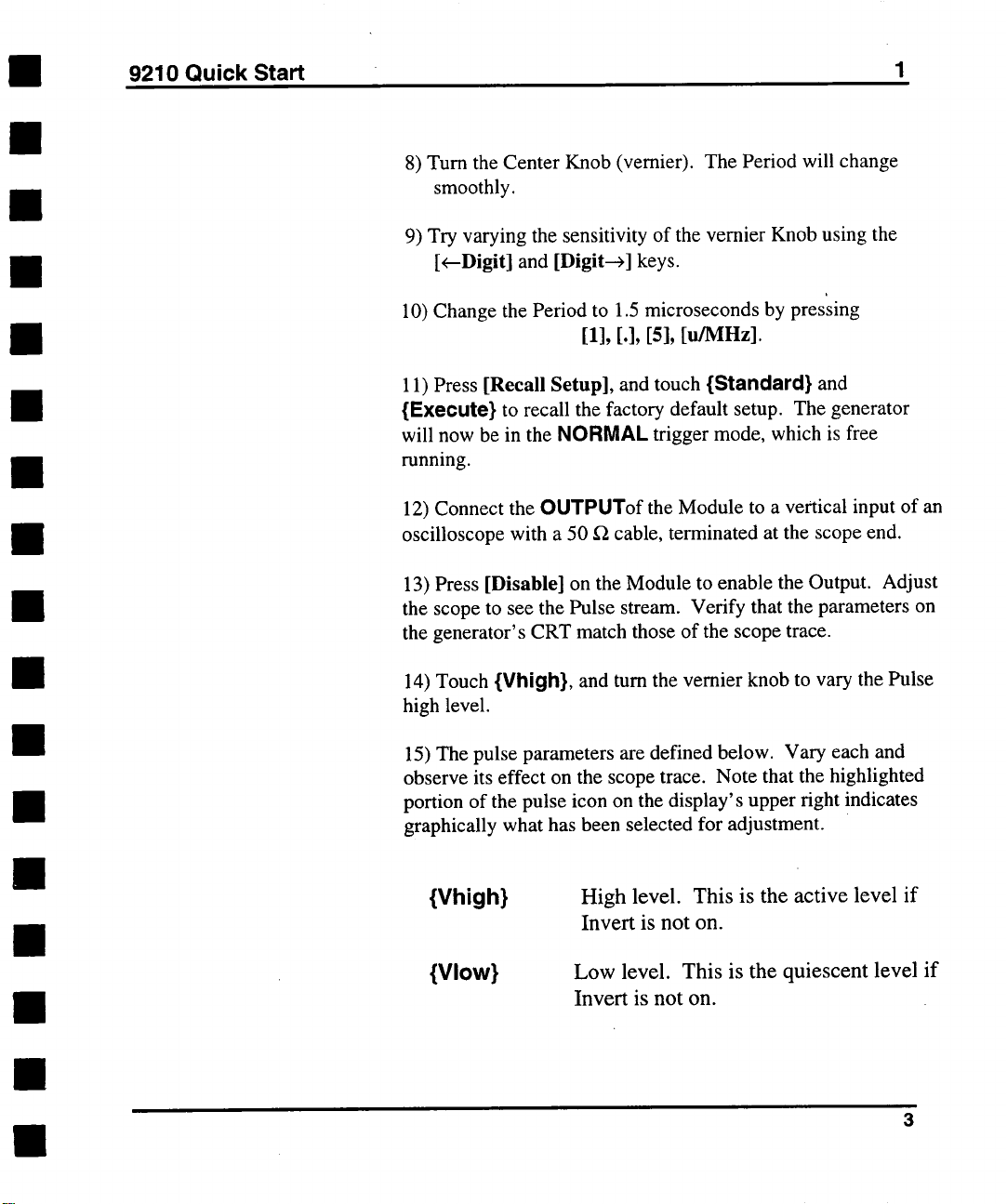
14) Touch {Vhigh}, and turn the vernier knob to vary the Pulse
high level.
15) The pulse parameters are defined below. Vary each and
observe its effect on the scope trace. Note that the highlighted
portion of the pulse icon on the display’s upper right indicates
graphically what has been selected for adjustment.
{Vhigh}
{Vlow}
High level. This is the active level if
Invert is not on.
Low level. This is the quiescent level if
Invert is not on.
Page 13
1
9210 Quick Start
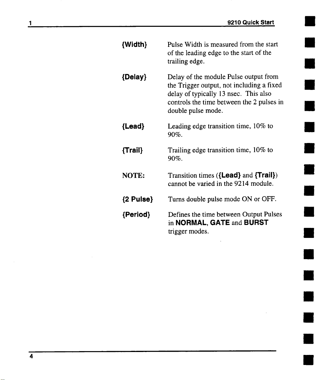
{Width}
{Delay}
{Lead}
{Trail}
NOTE:
{2 Pulse}
{Period}
Pulse Width is measured from the start
of the leading edge to the start of the
trailing edge.
Delay of the module Pulse output from
the Trigger output, not including a fixed
delay of typically 13 nsec. This also
controls the time between the 2 pulses in
double pulse mode.
Leading edge transition time, 10% to
9O%.
Trailing edge transition time, 10% to
90%.
Transition times ({Lead} and {Trail})
cannot be varied in the 9214 module.
Turns double pulse mode ON or OFF.
Defines the time between Output Pulses
in NORMAL, GATE and BURST
trigger modes.
Page 14
2 GETTING AROUND THE FRONT PANEL
Accessing the
Control Displays
DISPLAY
Keys
[T.,~Q.. ]
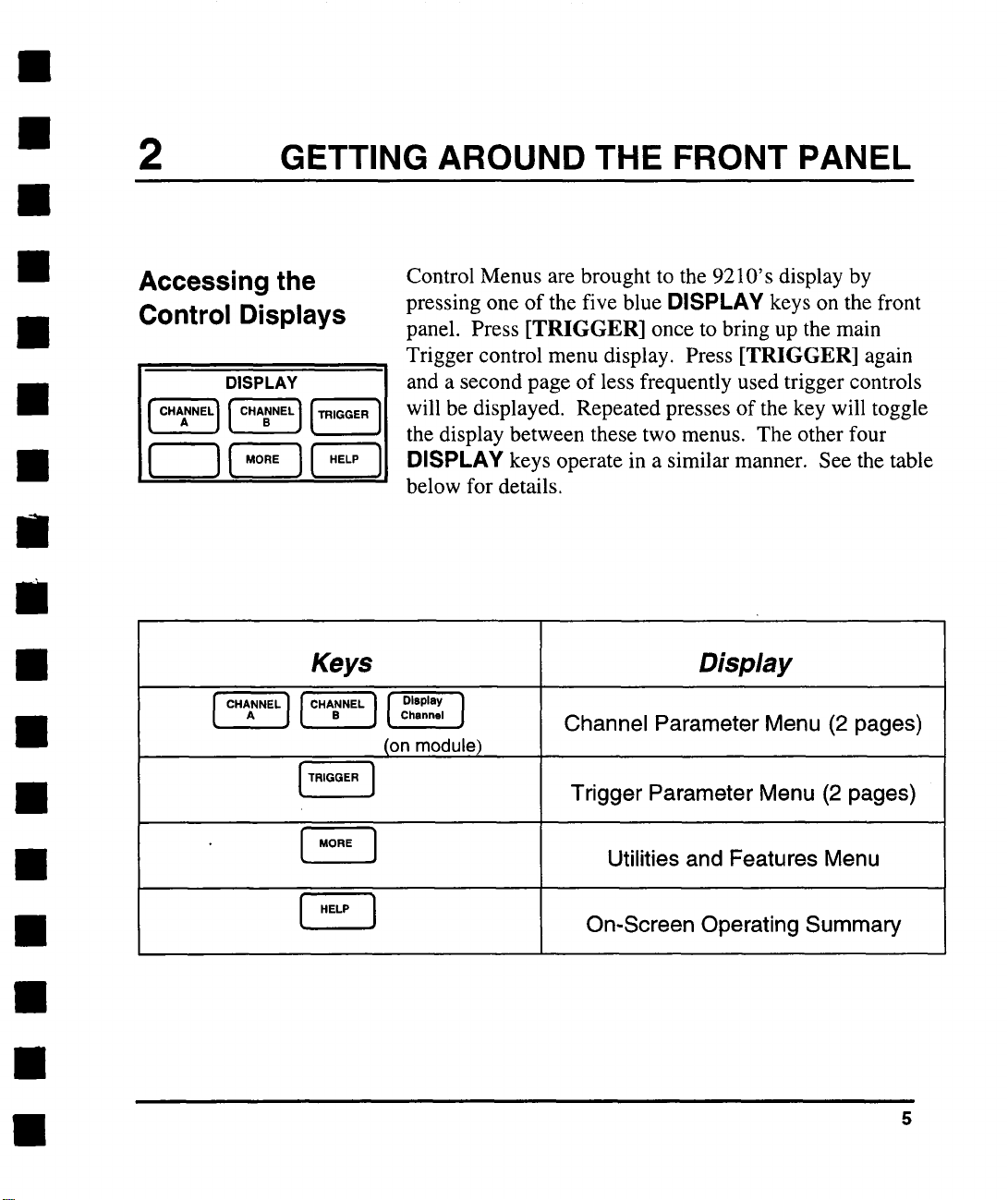
Control Menus are brought to the 9210’s display by
pressing one of the five blue DISPLAY keys on the front
panel. Press [TRIGGER] once to bring up the main
Trigger control menu display. Press [TRIGGER] again
and a second page of less frequently used trigger controls
will be displayed. Repeated presses of the key will toggle
the display between these two menus. The other four
DISPLAY keys operate in a similar manner. See the table
below for details.
Display
Channel Parameter Menu (2 pages)
Ion module)
Trigger Parameter Menu (2 pages)
[ ~,o., ]
[ .E.. ]
Utilities and Features Menu
On-Screen Operating Summary
Page 15
2
Getting Around the Front Panel
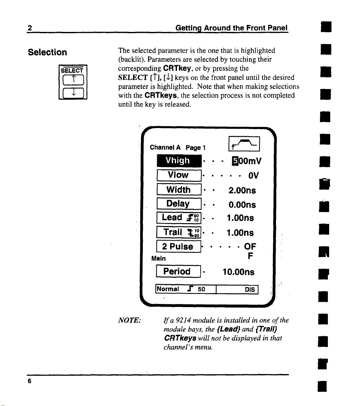
Selection
The selected parameter is the one that is highlighted
(backlit). Parameters are selected by touching their
corresponding CRTkey, or by pressing the
SELECT [1"], [,l,] keys on the front panel until the desired
parameter is highlighted. Note that when making selections
with the CRTkeys, the selection process is not completed
until the key is released.
Channel A Page I
Vhigh
I Vlow
I" "
Width I’"
Delay
J" ¯
[Lead .:r~ol..
¯ Boomv
¯
¯ - OV
2.00ns
0.00ns
1.00ns
Trail ~L~I" ¯
2 Pulse ~ ¯
Main
J Period I"
JNormal ,1" SO I
NOTE:
6
If a 9214 module is installed in one of the
module bays, the {Lead} and {Trail}
CRTkey$ will not be displayed in that
channel’s menu.
1.00ns
---OF
F
10.00ns
DIS I
Page 16

Getting Around the Front Panel
2
Adjusting
Parameters with
the Numeric
Keypad
Adjusting
Parameters with
the Rotary Knob
A precise value for the selected parameter can be entered
by pressing the numbers on the numeric keypad. Each
number pressed will be displayed in the information
window at the bottom of the CRT. The [Back Space] key
is provided for deleting erroneous key presses. The [ +/- ]
key will toggle the sign of the number being entered, and
may be pressed at any time before terminating entry. After
the sign and numeric portion of the desired value have been
punched in, entry with the appropriate multiplier is
terminated by pressing one of the four unit/entry keys
([n/GHz], [u/MHz], [m/kHz], or [Enter/Hz]) at the right
of the keypad.
Continuous adjustment of the selected parameter can be
accomplished using the concentric Rotary Knob. The
Outer Ring Knob (range select) will set the parameter’s
value in a 1-2-5 Sequence. As a convenience, if the Outer
Knob is rotated by only one position and then turned back,
the original value will be restored, even if that value was
not a 1, 2 or 5. The Center Knob (vernier) will change
the value in a continuous, analog fashion. The sensitivity
of the vernier Knob is controlled by using the Digit select
keys located below the Knob. The [Digit --->] key will
move the selected digit to the right, for finer adjustment,
and the [<--Digit] key will move the selected digit left, for
more coarse adjustment. Note that the [<---Digit] key allows
for the changing of adjustment sensitivity beyond the digits
currently displayed.
Page 17
2 Getting Around the Front Panel
Non-Numeric
Entries
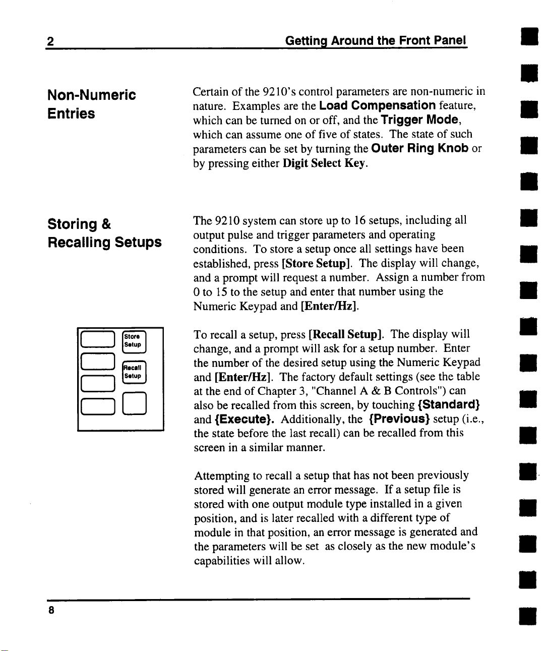
Storing &
Recalling Setups
Certain of the 9210’ s control parameters are non-numeric in
nature. Examples are the Load Compensation feature,
which can be turned on or off, and the Trigger Mode,
which can assume one of five of states. The state of such
parameters can be set by tuming the Outer Ring Knob or
by pressing either Digit Select Key.
The 9210 system can store up to 16 setups, including all
output pulse and trigger parameters and operating
conditions. To store a setup once all settings have been
established, press [Store Setup]. The display will change,
and a prompt will request a number. Assign a number from
0 to 15 to the setup and enter that number using the
Numeric Keypad and [Enter/l-lz].
To recall a setup, press [Recall Setup]. The display will
change, and a prompt will ask for a setup number. Enter
the number of the desired setup using the Numeric Keypad
and [Enter/Hz]. The factory default settings (see the table
at the end of Chapter 3, "Channel A & B Controls") can
also be recalled from this screen, by touching {Standard}
and {Execute}. Additionally, the {Previous} setup (i.e.,
the state before the last recall) can be recalled from this
screen in a similar manner.
Attempting to recall a setup that has not been previously
stored will generate an error message. If a setup file is
stored with one output module type installed in a given
position, and is later recalled with a different type of
module in that position, an error message is generated and
the parameters will be set as closely as the new module’s
capabilities will allow.
Page 18
Getting Around the Front Panel
2
Executing Action
Commands
Some CRTkeys invoke actions instead of selecting
parameters, but these actions do not take place immediately
upon releasing the key. A confirmation box will appear on
the screen, and {Execute} must be touched to continue
with the selected action. If the action key was touched in
error, {Cancel} can be touched and the action will not
occur,
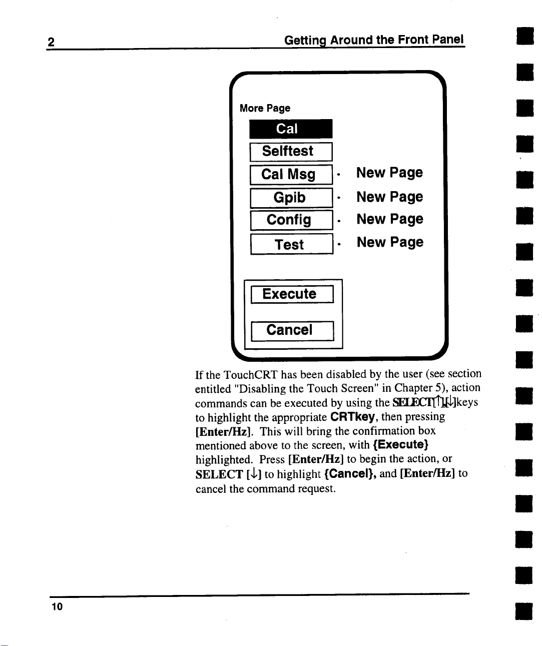
{Cal}, at the top of the More menu page is an example of
an action key. The key is used to initiate a self-calibration
cycle. When the key is touched, a box appears at the
bottom of the display containing two new CRTkeys,
{Execute} and {Cancel} (see figure below).
{Execute} is touched, the 9210 will proceed to calibrate
itself. If {Cancel} is touched, no action will occur.
9
Page 19
2
More Page
Selftest
Ii
Getting Around the Front Panel
I
I
Cal Meg -
New Page
New Page
II Gpib
Config New Page
Ii
New Page
I Test I
Execute
I
I
10
I Cancel
If the TouchCRT has been disabled by the user (see section
entitled "Disabling the Touch Screen" in Chapter 5), action
commands can be executed by using the ~F.CIT~]keys
to highlight the appropriate CRTRey, then pressing
[Enter/l-lz]. This will bring the confirmation box
mentioned above to the screen, with {Execute}
highlighted. Press [Enter/I-Iz] to begin the action, or
SELECT [,1,] to highlight {Cancel}, and [Enter/l-lz] to
cancel the command request.
Page 20
Getting Around the Front Panel
2
Manually
Triggering the
Generator
Alternate
Parameter
Formats
I
DISPLAY
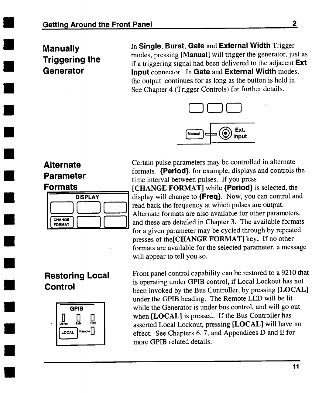
In Single, Burst, Gate and External Width Trigger
modes, pressing [Manual] will trigger the generator, just as
if a triggering signal had been delivered to the adjacent Ext
Input connector. In Gate and External Width modes,
the output continues for as long as the button is held in.
See Chapter 4 (Trigger Controls) for further details.
Ext
Input
Certain pulse parameters may be controlled in alternate
formats. {Period}, for example, displays and controls the
time interval between pulses. If you press
[CHANGE FORMAT] while {Period} is selected, the
display will change to {Freq}. Now, you can control and
read back the frequency at which pulses are output.
Alternate formats are also available for other parameters,
and these are detailed in Chapter 3. The available formats
for a given parameter may be cycled through by repeated
presses of the[CHANGE FORMAT] key. If no other
formats are available for the selected parameter, a message
will appear to tell you so.
Restoring Local
Control
GPIB
D n n
Listen Talk
SRQ
~A’~ Rernote 0
Front panel control capability can be restored to a 9210 that
is operating under GPIB control, if Local Lockout has not
been invoked by the Bus Controller, by pressing [LOCAL]
under the GPIB heading. The Remote LED will be lit
while the Generator is under bus control, and will go out
when [LOCAL] is pressed. If the Bus Controller has
asserted Local Lockout, pressing [LOCAL] will have no
effect. See Chapters 6, 7, and Appendices D and E for
more GPIB related details.
11
Page 21
2 Getting Around the Front Panel
Module Controls
- Enabling or
Inverting the
Pulse Output
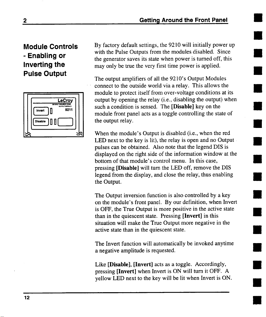
By factory default settings, the 9210 will initially power up
with the Pulse Outputs from the modules disabled. Since
the generator saves its state when power is turned off, this
may only be true the very first time power is applied.
The output amplifiers of all the 9210’s Output Modules
connect to the outside world via a relay. This allows the
module to protect itself from over-voltage conditions at its
output by opening the relay (i.e., disabling the output) when
such a condition is sensed. The [Disable] key on the
module front panel acts as a toggle controlling the state of
the output relay.
When the module’s Output is disabled (i.e., when the red
LED next to the key is lit), the relay is open and no Output
pulses can be obtained. Also note that the legend DIS is
displayed on the right side of the information window at the
bottom of that module’s control menu. In this case,
pressing [Disable] will turn the LED off, remove the DIS
legend from the display, and close the relay; thus enabling
the Output.
12
The Output inversion function is also controlled by a key
on the module’s front panel. By our definition, when Invert
is OFF, the True Output is more positive in the active state
than in the quiescent state. Pressing [Invert] in this
situation will make the True Output more negative in the
active state than in the quiescent state.
The Invert function will automatically be invoked anytime
a negative amplitude is requested.
Like [Disable], [Invert] acts as a toggle. Accordingly,
pressing [Invert] when Invert is ON will turn it OFF. A
yellow LED next to the key will be lit when Invert is ON.
Page 22
Getting Around the Front Panel
2
Power - Turning
the Generator On
& Off
POWER
On / Disable
The 9210’s power supply will automatically adjust to local
power line voltages of 115 or 220 VAC, _ 20% and to line
frequencies between 48 Hz and 448 Hz. Just attach the
power cord to the rear panel connector and plug it in. The
Main Circuit Breaker switch on the rear panel should
always be left in the ON position. This is a true’ circuit
breaker, which will trip if the generator draws line current
in excess of 5 Amps. The square, white [On/Disable] key,
under the POWER heading on the front panel acts as a
toggle. Pressing this key will tum the generator on and off.
13
Page 23
3 CHANNEL A. & B CONTROLS
General
Information
Controlling
Vertical
Characteristics
In most cases, the controls for Channels A and Channel B
operate identically, regardless of which Output Module is
installed in which slot. Considerations specific to the
Model 9211, 9212 9213 and 9214 Output Modules will be
presented at the end of this chapter.
The term Pulse Output, as used in this chapter, refers to the
signal at the Module’s True Output, which is the upper
connector, labeled OUTPUT, on the module’s front panel.
Some modules have a Complementary Output, labeled
OUTPUT. This output will carry a signal of the same
voltage levels as the True Output, but with opposite signal
orientation
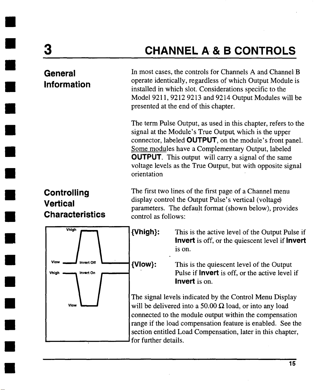
The first two lines of the first page of a Channel menu
display control the Output Pulse’s vertical (voltage)
parameters. The default format (shown below), provides
control as follows:
{Vhigh}:
This is the active level of the Output Pulse if
Invert is off, or the quiescent level if Invert
is on.
Vlow
{Vlow}: This is the quiescent level of the Output
’
The signal levels indicated by the Control Menu Display
will be delivered into a 50.00 f~ load, or into any load
connected to the module output within the compensation
i
range if the load compensation feature is enabled. See the
section entitled Load Compensation, later in this chapter,
for further details.
Pulse if Invert is off, or the active level if
Invert is on.
15
Page 24
3
Channel A & B Controls
Channel A Page1Iif./~_
Vhigh
¯
- ¯ ~O0mV
IVlow J ......
I Width I ""
i Dela~ i’"
i’-°ad ~,’o°i--
~rail~°l--
2 Pulse I ...... OFF
Main
IPeri°d I " lO.OOns
l Normal ZSO I ols I
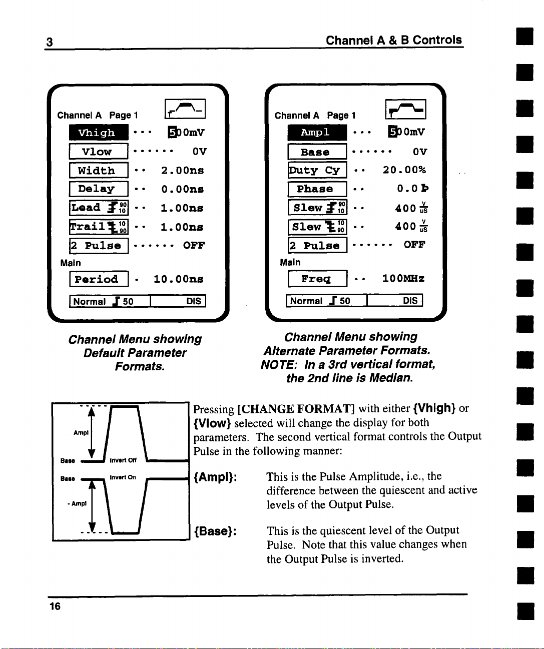
Channel Menu showing
Default Parameter
Formats.
2.00ns
0.00ns
Z. 00ns
Z.00ns
0V
I
Channel A Page I
Ampl
Base I ...... 0V
I
¯.. L’~nmV
l--
-
I Slew ~ ,’o°1
°
ISle. IZ:
2 Pulse ......
Main
Fre~
I
I Normal .r so I D,S I
Channel Menu showing
Alternate Parameter Formats.
NOTE: In a 3rd vertical format,
the 2nd line is Median.
I "" 100MHz
J~l
~w
20.00%
0.0]>
4005
400~
OFF
16
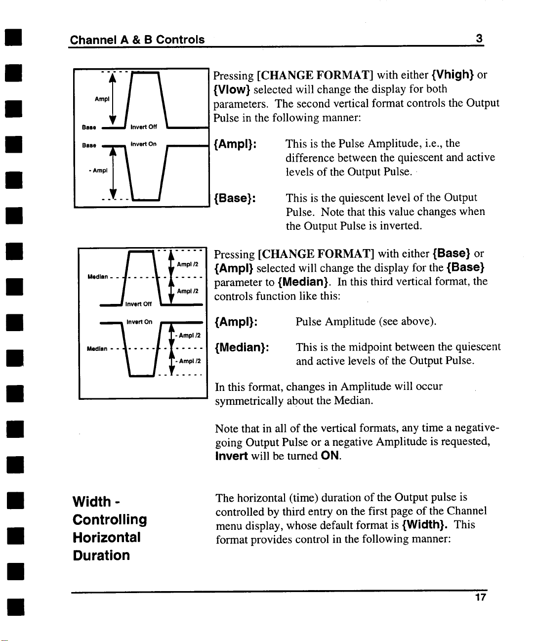
Pressing [CHANGE FORMAT] with either {Vhigh} or
{Vlow} selected will change the display for both
parameters. The second vertical format controls the Output
Pulse in the following manner:
{Ampl}: This is the Pulse Amplitude, i.e., the
difference between the quiescent and active
levels of the Output Pulse.
{Base}:
This is the quiescent level of the Output
Pulse. Note that this value changes when
the Output Pulse is inverted.
Page 25
Channel A & B Controls
3
Pressing [CHANGE FORMAT] with either {Vhigh} or
{VIow} selected will change the display for both
parameters. The second vertical format controls the Output
Pulse in the following manner:
Base ,~lnvert On
/
"°" .... .....
l
- Ampl/2
{Ampl}: This is the Pulse Amplitude, i.e., the
difference between the quiescent and active
levels of the Output Pulse.
{Base}:
Pressing [CHANGE FORMAT] with either {Base} or
{Ampl} selected will change the display for the {Base}
parameter to {Median}. In this third vertical format, the
controls function like this:
{Ampl}: Pulse Amplitude (see above).
{Median}:
In this format, changes in Amplitude will occur
symmetrically about the Median.
Note that in all of the vertical formats, any time a negative-
going Output Pulse or a negative Amplitude is requested,
Invert will be turned ON.
This is the quiescent level of the Output
Pulse. Note that this value changes when
the Output Pulse is inverted.
This is the midpoint between the quiescent
and active levels of the Output Pulse.
Width Controlling
Horizontal
Duration
The horizontal (time) duration of the Output pulse
controlled by third entry on the first page of the Channel
menu display, whose default format is {Width}. This
format provides control in the following manner:
17
Page 26
3
Channel A & B Controls
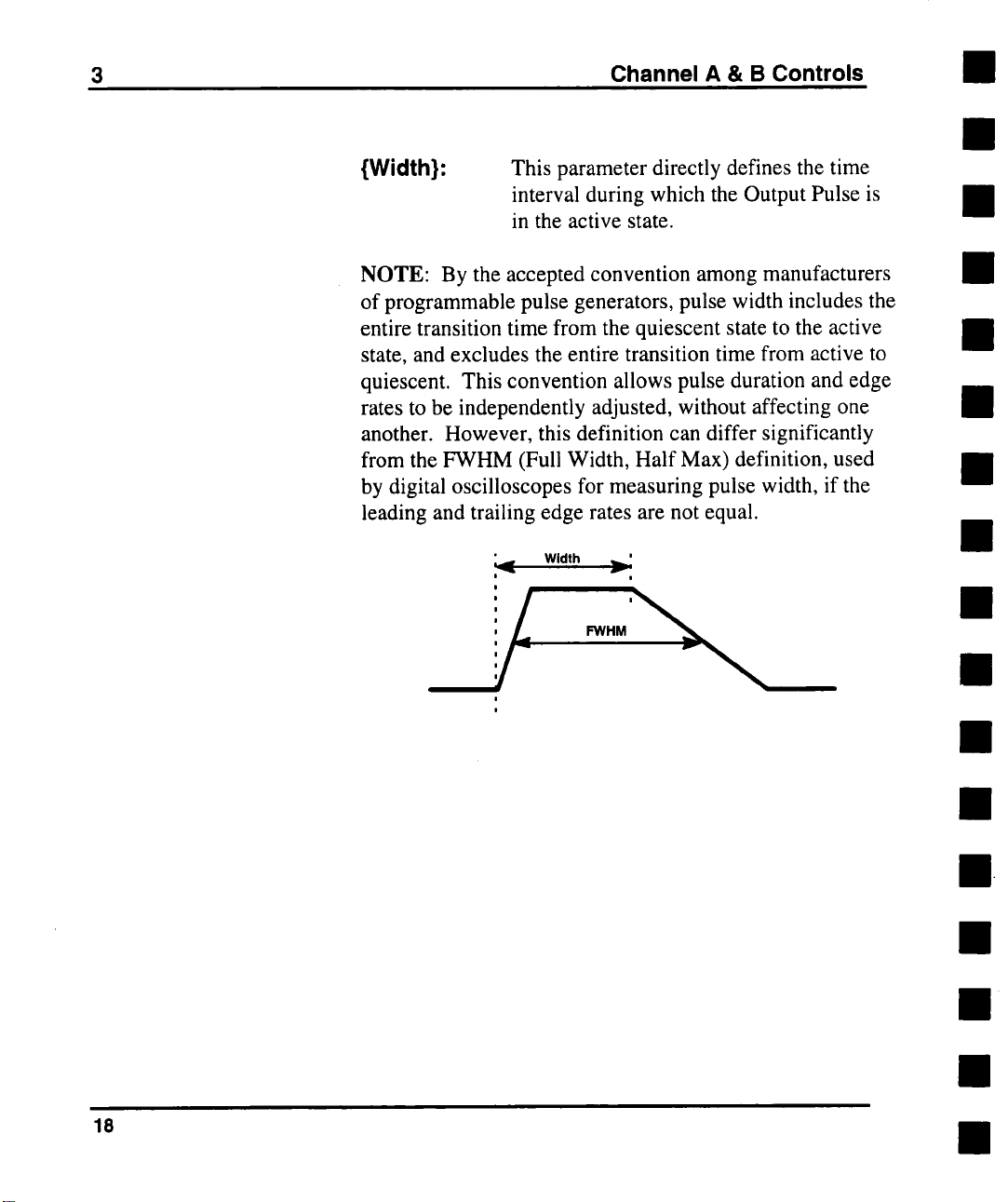
{Width}:
This parameter directly defines the time
interval during which the Output Pulse is
in the active state.
NOTE: By the accepted convention among manufacturers
of programmable pulse generators, pulse width includes the
entire transition time from the quiescent state to the active
state, and excludes the entire transition time from active to
quiescent. This convention allows pulse duration and edge
rates to be independently adjusted, without affecting one
another. However, this definition can differ significantly
from the FWHM (Full Width, Half Max) definition, used
by digital oscilloscopes for measuring pulse width, if the
leading and trailing edge rates are not equal.
Width
"~,
i
i
~’
J
18
Page 27
Channel A & B Controls
3
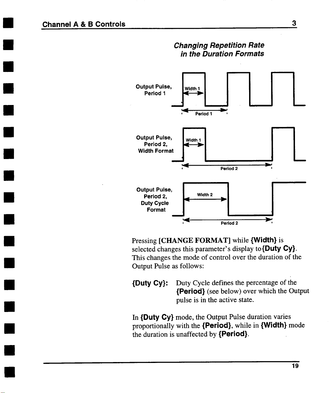
Changing Repetition Rate
in the Duration Formats
;~-~
Width 2
Period 2
]
~"
19
Period 2,
Duty Cycle
Output u’se’ I
Format
Pressing [CHANGE FORMAT] while {Width} is
selected changes this parameter’s display to{Duty Cy}.
This changes the mode of control over the duration of the
Output Pulse as follows:
{Duty Cy}: Duty Cycle defines the percentage of the
{Period} (see below) over which the Output
pulse is in the active state.
In {Duty Cy} mode, the Output Pulse duration varies
proportionally with the {Period}, while in {Width} mode
the duration is unaffected by {Period}.
Page 28
3
Channel A & B Controls
Duty Cycle mode is merely a method the generator uses to
derive pulse {Width} values. In modes where {Period}
has no operational meaning (such as Single trigger mode
see Chapter 4), the {Width} is determined by {Duty Cy}
{Period} X 0.01.
Delay Controlling
Horizontal
Position
Control of the Output Pulse’s horizontal (time) position
provided by the fourth line of the first page of the Channel
menu display. This control is effected as follows:
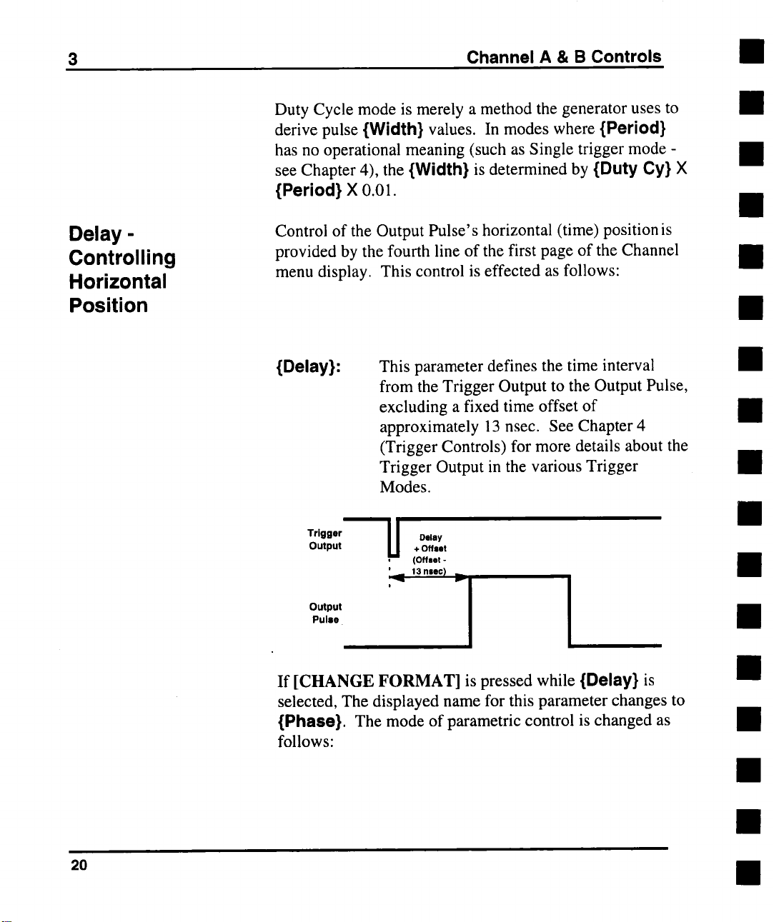
{Delay}:
This parameter defines the time interval
from the Trigger Output to the Output Pulse,
excluding a fixed time offset of
approximately 13 nsec. See Chapter 4
(Trigger Controls) for more details about the
Trigger Output in the various Trigger
Modes.
Trigger
Output
Output
Pulse
U
Delay
+ Offset
(Offset
13 nsec)
20
If [CHANGE FORMAT] is pressed while {Delay} is
selected, The displayed name for this parameter changes to
{Phase}. The mode of parametric control is changed as
follows:
Page 29
Channel A & B Controls
3
Controlling
Transition Rates
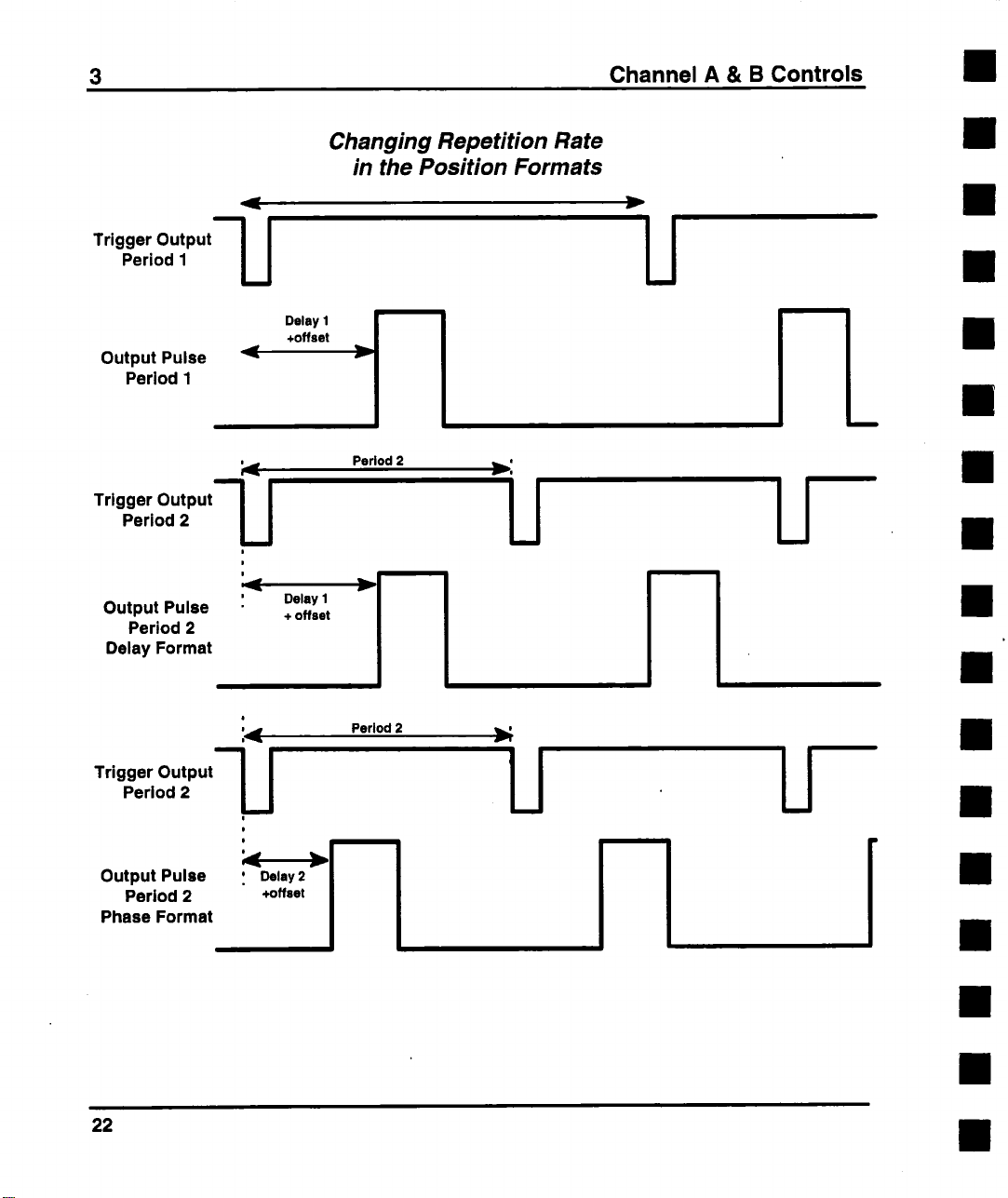
{Phase}:
Resolution in {Phase} format is always 0.1_ (i.e. one part
in 3600). Depending upon the {Period} setting, this may
be more or less resolution than the {Delay} format
provides.
The fifth and sixth lines of the first page of a Channel menu
display control the Output Pulse’s transition time (edge
speed). The default format for these parameters provide
control as follows:
Phase mode provides delay control in a
manner proportional to {Period}, similar to
the way Duty Cycle format controls pulse
duration. In this operating mode, the pulse’s
position is expressed as a phase angle, with
O_ corresponding to the minimum {Delay}
setting (i.e. the offset). This phase angle
maintained as {Period} is varied. When
{Phase} has been set, the Pulse {Delay} =
{Phase}/360 X {Period}.
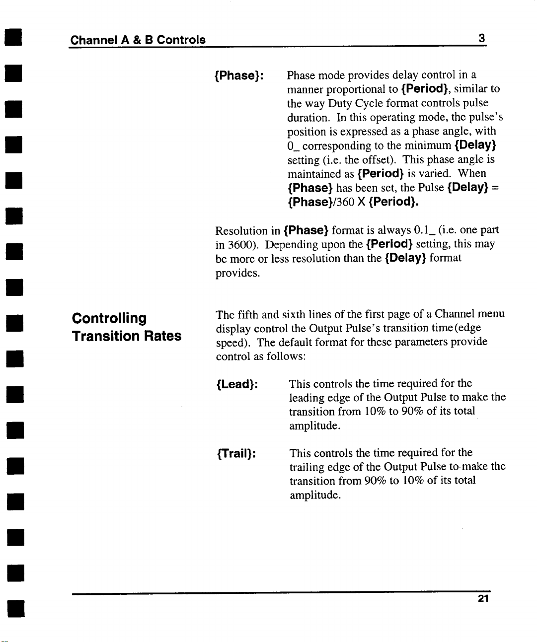
{Lead}:
{Trail}:
This controls the time required for the
leading edge of the Output Pulse to make the
transition from 10% to 90% of its total
amplitude.
This controls the time required for the
trailing edge of the Output Pulse to.make the
transition from 90% to 10% of its total
amplitude.
21
Page 30
3
Trigger Output’-’~
Period 1
Output Pulse
Period 1
Channel A & B Controls
Changing Repetition Rate
in the Position Formats
Delay I
+offset
i
i~.dw
Tr’g0er Ou,.u,--I I
Period 2
U
|
|
Output Pulse
Period 2
Delay Format
Trigger Output"~
Period 2
Output Pulse , Delay2
Period 2
Phase Format
Delay I
+ offset
0
0
+offset
Period 2
~ i
I
Period 2
22
Page 31

Channel A & B Controls
3
Pressing [CHANGE FORMAT] when either {Lead} or
{Trail} is selected will change the display for both these
parameters to {Slew}. Note that the icon within each
CRTkey denotes which edge’s slew rate that key will
control. The mode of control changes as follows:
.9 A1
{Slew}:
Slew Rate defines the slope of the selected
edge during its 10% to 90% (or 90% to
10%) transition.
Changing Amplitude in the
Transition Time formats
In Lead / Trail
At1 = At2
Atl
In Slew mode,
&Vl/ Z~tl ----- AV2.J At2
...................... i__
.9 AI i AV1
--~ A, 14~--
.9A2
23
Page 32

3
It follows from the parameter definitions that changing the
amplitude of the Output Pulse in {Leafl}/{Trail} mode will
cause a change in the edge slopes, while in {Slew} mode,
the slopes will remain constant.
Note that in the 9214 module, transition time is a fixed
parameter. Therefore, {Load}, {Trail}, and {Slew} cannot
be adjusted in that module. Additionally, the {Slew}
format is not supported in the 9212 module.
Channel A & B Controls
Dynamic Range
and Transition
Rates
In the 9211 and 9213 Output modules, linear edge
transitions are created by the charging (or discharging)
capacitors by a programmable current source. The wide
range of edge speeds offered by these modules is achieved
by switching among a series of capacitors in ranges
appropriate to the edge rates requested. This results in each
of these modules having several edge speed ranges. Each
range covers a span of values of approximately 25:1.
Additionally, each range overlaps the next slower range
over an area of about 2.5:1, except at the boundary of the
two fastest ranges, where the overlap is 2:1.
24
Page 33

Channel A & B Controls
3
If an attempt is made to create a pulse with edge speeds
sufficiently different from One another as to exceed the
boundaries of a given range, priority will be given to the
currently selected edge. The range will be switched to
accommodate the value requested for the selected edge, the
displayed value for the other edge will be updated, and an
asterisk (*) will be placed on the display to the left of the
other edge’s CRTkey, to alert the user that the value has
been altered due to the change in ranges. The previous
value for the unselected edge is saved in memory and will
be restored when possible (i.e. when the boundary range is
re-crossed by the selected edge). For information about the
range boundaries for a given Output Module, see the
Module’s Technical Data Sheet.
Double Pulse
Operation
The state of the Double Pulse operating mode is controlled
by the {2 Pulse} CRTkey. In Normal and Single Trigger
modes, when {2 Pulse} is OFF, one Output Pulse will
,follow each Trigger Output. Turning {2 Pulse} ON in
either of these trigger modes will result in two Output
Pulses for each Trigger Output. Be aware that {Delay}
must be set to a value greater than {Width} in order to see
the second pulse.
Double Pulse Operation
Trigger
Output
DelayOflset_.j~!
(- 11 .s) .,
Output
Pulse
Double-Pulse
Delay .
!
25
Page 34

3 Channel A & B Controls
Note that the first of the two Output Pulses in this operating
mode will occur approximately 2 nsec sooner than a single
Output Pulse programmed for zero delay will. In other
words, the delay offset for Double Pulse operating mode is
about 2 nanoseconds less than in the standard operating
mode.
Double Pulse Operation is compatible with all Trigger
Modes except External Width. See the section entitled
"Double Pulse Interactions" in Chapter 4 (Trigger Controls)
for further details.
Controlling
Repetition Rate
The last line of the first page of a Channel menu display
provides control over the Output Pulse repetition rate. The
default format is:
{Period}:.
Pressing [CHANGE FORMAT] when {Period} is
selected will change the display for this parameter to:
{Freq}: This controls the frequency of Output Pulses
The difference between these formats is only in the way the
rate is specified, and not in any sense an operational
difference. This parameter has meaning in Single Trigger
Mode only if the pulse duration is specified in {Duty Cy}
format, in which it is used to calculate the Output Pulse’s
Width, or if pulse position is specified in {Phase} format,
where {Period} will be used to calculate the Delay See
the "Trigger Modes" section of Chapter 4 for further
details.
This defines the time between Output Pulses
in Normal, Burst and Gate Trigger Modes.
in Normal, Burst and Gate Trigger Modes.
26
Page 35

Channel A & B Controls
3
This parameter is also available on the first page of the
Trigger menu.
Parameter
Conflicts
It is possible that while adjusting the parameters detailed
above, a situation will arise where the requested parameter
set is in violation of the basic parameter definitions (see the
Glossary, Appendix F, for a listing of the parameter
definitions). In such a case, blinking question marks (?)
will appear next to each of those parameters involved in the
Conflict condition. This occurs when a requested set of
parameters is beyond the specified range of operation due
to the interaction of two or more parameters.
27
Page 36

3
Pictorial representation of Pulse Parameters
Trigger
Output
Period (or 1/freq) I
Delay ~
+13 neec , ,
Output PulIie,
Invert Off,,
,,(-Arnpl) ~--, ............
Output Pulle,lnvert On
’
Width
~ ii D
0D 0
uu
o0 |
::
. .;
Period (or 1/freq)
’ ’
" ...
9Amp,
, .
I i
0 0
;
"A mp I/2
t t ~" / T
.......... ,
r (’Ampl) .Ampl ..... t-plan
Vhlgh
"m"’I / .......
Channel A & B Controls
..............
1
\- - ~..d,sn
~ "~"
... .... Vhlgh or Base Bmmm
~ ~r
Amp’ 12
28
........... *- v,ow. ......
-~ Width
Notes: 1) Duty Cycle = (Width ! Period) X 100%
2) Phase = (Delay / Period) X
Guided by the requirements of your application, select from
among the indicated parameters those which can be altered
to both resolve the conflict and satisfy the demands of your
measurement. The following conditions must be true in
order to avoid conflict:
Vhigh > Vlow
1)
2) Lead < Width
Vhigh - Vlow _> Min. Amplitude
3)
Vhigh - Vlow ___ Max. Amplitude
4)
1.25 X Lead < Width
5)
°
.X
Page 37

Channel A & B Controls
3
if Limits are enabled (see the section entitled Limiting
the Output Levels, below):
6) Vhigh 2 Vmax
7) Vlow 3 Vmin
if {2 Pulse} is OFF and Trigger Mode is Normal,
Burst or Gate:
8)
Width + (1.25 X Trail) < Period
Width + Retrig < Period
9)
Delay + Retrig < Period
10)
if {2 Pulse} is ON:
11) Width + (1.25 X Trail) < Delay
12) Width + Retrig < Delay
if {2 Pulse} is ON and Trigger Mode is Normal, Burst
or Gate:
13) Delay + Width + (1.25 X Trail) < Period
14) Delay + Width + Retrig < Period
NOTES: The 0% to 100% transition time needed to
determine conflicts is 1.25 times greater than the
10% to 90% displayed {Lead} and {Trail}
times.
29
Page 38

3 Channel A & B Controls
"Retrig" is a time interval during which one of
the 9210’s timing generators cannot be retriggered without possibly compromising proper
device operation. The exact magnitude of
Retrig is dependent upon several operating
conditions. It is usually negligibly small and
always less than 5 nsec.
Load
Compensation
At the top of the second page of the Channel menu display
is a CRTkey which controls the state of the 9210’s Load
Compensation feature. When {Loafleornp} is OFF, the
load is assumed to be 50.00 fL The voltage levels
delivered to the actual load, based on that assumption, may
be up to two times those specified, dependent on the actual
load resistance. When {Loadcomp} is turned ON, the
generator measures the load connected to the Module
Output, and calculates a correction factor. It then uses that
factor to make the necessary DC corrections to deliver the
displayed voltage levels to any load resistance from 47f~ to)
1M~:,, If the load resistance is subsequently changed,
{Loadcomp} must be turned OFF, then ON again to
recalculate the correction factor.
3O
Page 39

Channel A & B Controls
3
r
Channel A Page 2
ILoadcomp
TTL set
I
ECL set
I
Limits
I
V max
I V min
eturn I New Page
R
I
INormal I 50 I D,sl
Note that the Load Compensation algorithm used in the
9210 is valid for resistive loads only, and cannot correct for
damping, ringing or oscillations caused by reactive loads,
or for reflections due to transmission line mismatching.
Nor can it correct for loads terminated to voltages other
than ground (e.g. 50 ~ to -2 V).
I
I
¯ ¯ ¯ ~0mV
OFF
OFF
500mV
31
Page 40

3 Channel A & B Controls
Logic Family
Presets
Limiting the
Output Levels
{TTL set} and {ECL set} are action keys (see "Executing
Action Commands" in Chapter 2) which allow the user to
quickly assign standard logic family voltage levels to the
Output Pulse.
{TTLset} will set {Vlow} to 300 mV and {Vhigh} to 3.5
V. If the Vertical format is other than {Vhigh}/{Vlow}, it
will be changed to this format.
{ECLset} will set {Vlow} to -1.9 V and {Vhigh} to
-800 inV.
The last three lines of the second page of a Channel menu
display provide the user with a means of limiting the
requested voltage levels of the Output Pulse, to protect a
delicate device under test from application of potentially
harmful signal levels.
If {Limits} is ON, then {Vhigh} cannot be set above
{Vmax}, and {Vlow} cannot be set below {Vmin}. Any
attempt to exceed either limit will produce the message
"Value limited to user limit". With {Limits} OFF, the
Module’s full specified output swing is available.
Module
Considerations
32
The 9212 and 9214 Output Modules, which feature very
fast edge rates (as fast as 300 psec), have slightly different
Control Menu Displays. The first pages of the menus for
these two modules are pictured below. In the 9212 module,
the transition times of both edges of the Output Pulse are
adjusted in common. Therefore, there is no {Trail}
CRTkey. Both edges are adjusted by selecting {Lead},
but the value of {Trail} is updated on the display.
Transition time is fixed at 300 psec in the 9214 module, so
there are no CRTkeys for {Lead} or {Trail} on that
module’s control menu.
II
II
Page 41

Channel A & B Controls 3
r
ChannelA Page1
I Vhigh
I
- - - 500mV
Channel B Page 1 I T"/--~’- I
I vhig I"" 5oo v
I Vlow
I Width
I Delay
Trail ~
12 Pulse I
Main
IN°rmal I 50 I
9212 Module Control
Menu Display - Page 1
...... 0V
- ¯
I
I
2.00ns
- ¯
0.00ns
¯ ¯
0. ~ns
¯ ¯
0.50ns
...... OFF
¯
10.00ns
I vlo I""
ov
I width I’" 2.00ns
Delay
2 Pulse I ......
Main
[Period I " 10.00ns
DIS l
The 9210 Mainframe’s display also indicates the specified
Transition Time tolerances for any given setting in the
9212. When the LEAD menu box is selected on the 9210’s
TouchCRT, the tolerance window will be displayed to the
right of the parameter’s name (where the edge symbol
appears when the key is not selected). For example, when
LEAD is set to 0.7 nsec, the displayed tolerance window
will be +_440 psec. These limits will be updated as the
value is varied. Note that the tolerance window applies to
the trailing edge as well as the leading edge.
IN°rmal I50 I
9214 Module Control
Menu Display- Page 1
¯
- 0. ~ns
OFF
DIS I
33
Page 42

3 Channel A & B Controls
r
Channel A Page2 14¢J’--~- I
ILoadcomp I ...... OFF
J TTL set J
I ECL set I
I I---
vmin
l
Output
[ /Output [ ...... OFF
I Return I " New Page
IN°final 150 I DIS I
I ....
@ e e . e ¯ o
9212 and 9214 Module
Control Menu Display -
Page 2
500mV
¯
34
Because of the very fast edges these modules can generate,
the output amplifiers in the 9212 and 9214 require
matching terminations on their two outputs in order to
maintain proper edge fidelity. To allow the user to leave
unused outputs unterminated, options have been added to
the second page of the control menus for these modules to
disconnect and internally terminate either of the outputs in
50 ~. This menu is shown above.
Page 43

Channel A & B Controls
3
When {Output} is turned ON, the output relay for the
module’s normal outputconnects the output amplifier to the
SMA connector on the front panel. When {Output} is
turned OFF, the output relay for the module’s normal
output connects the output amplifier to an internal 50V2
precision resistor. The same applies to {/Output} and the
complemented output.
These CRTkeys interact with the [Disable] pushbutton on
the module’s front panel, which disconnects both outputs
simultaneously. For example, the complementary output is
only enabled when {/Output} is ON and [Disable] is OFF
(i.e. when the red LED on the module’s front panel is not
lit).
In the 9212 and 9214 modules, transition times are
specified from 20% to 80% of the full-scale transition,
rather than from 10% to 90%. This method of specifying
transition time is typical of fast transition time devices,
such as ECL and GaAs logic IC’s.
The table on the following page lists the factory default
settings for the Models 9211, 9212, 9213 and 9214 Output
Modules. These are the settings which will be obtained
when the {Standard} option is executed after the [Recall
Setup] key has been pressed. The Trigger parameters listed
below (from Mode through Input Z) are explained
Chapter 4, "Trigger Controls".
35
Page 44

3 Channel A & B Controls
Default Settings for Output Modules for the
LeCroy 9210 Programmable Pulse Generator
Module 9211 9212 9213 9214
Vhigh
Vlow
1.000 V
0 mV
500 mV 1.o60 v
500 mV
0 mV 0 mV 0 mV
Width 20.00 ns 2.00 ns 20.00 ns 2.00 ns
Delay 0.00 ns 0.00 ns 0.00 ns 0.00 ns
Lead 1.00 ns 0.40 ns 5.00 ns n/a
Trail 1.00 ns 0.40 ns
2 Pulse
Period
OFF
OFF
100 ns 100 ns 100 ns 100 ns
I
5.00 ns
OFF OFF
n/a
Loadcomp OFF OFF OFF OFF
Limits
ok OFF OFF OFF
Vmax 500 mV 500 mV 500 mV 500 mV
Vmin -500 mV -500 mV -500 mV -500 mV
Output ON
/Output ON ON ON ON
I!
ON
ON ON
Mode Normal Normal Normal Normal
Burst Ct 3 3 3 3
Level 0.10V 0.10V 0.10V 0.10V
Slope
Outlvl
Input Z
Positive Positive Positive Positive
0.10V
0.10V
0.10V
0.10V
50 D 50 D 50 D 50 D
Invert OFF OFF OFF OFF
Disable ON ON ON ON
36
Page 45

Channel A & B Controls
Output Module Parameter Limits for the
LeCroy 9210 Modular Pulse Generator
3
The table on the following page lists the specified limits for
the parameters detailed in this chapter for the Models 9211,
9212, 9213 and 9214 Output Modules. Vertical
specifications listed in parentheses 0 apply when driving a
high impedance load (>10 kf2), those without parentheses
apply when driving 50 f2.
Model 9211
Parameter
{Vhlgh}
{Vlow}
{Ampl} 50 mV 5.00 V 500 mV
{Base}
{Median}
0/Vidth}
{Duty Cy} 1% 99%
{Delay} 0 nsec
{Phase} 0
{Lead}
{Trail} 1.2 nsec
{Stew}
{Period}
{Freq} 2.2 Hz 250 MHz
MIn Max Min Max
-4,95 V +5.00 V -4.50 V
(-9.90 V)
-5.00 V +4.95 V -5.00 V +4.50 V
(- 10.00 V) (+9.90 V) (-5.00 V)
(100 mY)
-5.00 V +5.00 V -5.00 V
(-10.00 V)
-4.975 V +4.975 V
(-9.95O V)
2 nsec 450 msec 1.2 nsec 450 msec
1.2 nsec
0.1V/msec 3.3 kV/~sec N/A
4 nscc 450 msec 3.33 nsec
(+10.00 V) (-4.00 V) (+5.00 V) (-15.96 V)
(10.00 V) (i .oo v) (io.oo v)
(+10.00 V) (-5.00 V) (+5.00 V)
-4.75 V +4.75 V (-7.99 V) (+7.99 V)
(+9.950 V) (-4.50 V) (+4.50 V)
450 msec 0 nsec 450 msec
359.9 0
10msec 300 psec 1 nsec 6.5 nsec
10msec 300 psec 1 nsec
2.2 Hz 300 MHz 2.2 Hz
Model 9212
+5.00 V -7.98 V +8.00 V -4.50 V
(+4.00) (+16.00 V) (+15.96 V)
5.00 V 20 mV 16.00 V 500 mV
+5.00 V -8.00 V +8.00 V
1% 99% 1% 99%
359.9 _ 0
N/A 0.1 V/msec 2.3 kV/psec
450 msec 20 nsec
Model 9213 Model 9214
Min Max
(+16.00 V) (-4.00 V) (+5.00 V)
-8.00 V +7.98 V -5.00 V
(40 mV) (32.00 V) (1.00 V) (10.00 V)
(- 16.00 V) (+16.00 V) (-5.00 V) (+5.00 V)
(-15.98V) (+15.98 V) (-4.50 V)
5 nsec 450 msec 1.2 nsec
0 nsec 450 msec 0 nSCC
359.9 _ 0 359.9 _
95 msec 300 psec 300 psec
6.5 nsec 95msec 300 psec
450 msec 3.33 nsec 450msec
50 MHz 2.2 Hz 300 MHz
Min Max
+5.00 V
+4.50 V
(-5.00 V) (+4.00)
5.00 V
-5.00 V +5.00 V
-4.75 V +4.75 V
(+4.50 V)
450 msec
1% 99%
450 msec
300 psec
N/A N/A
37
Page 46

3 Channel A & B Controls
Values above the bold double line in the
table are the actual minimum and
maximum values which will be accepted by
the mainframe. Values below the bold
double line are guaranteed specifications
but the mainframe may accept values
outside the indicated range. Certain
combinations of the above parameters may
not be achievable simultaneously. See the
section of this chapter entitled Parameter
Conflicts for details.
38
Specifications subject to change without notice.
Page 47

4 TRIGGER CONTROLS
General
Information
The Trigger
Output
The 2 Output Modules in the 9210 are driven from a
common timebase, i.e. the channel outputs are both
referenced to the same trigger. This does not mean that the
two channels must both output their pulses at the same
time, or that they must be of identical width, but merely
that the repetition rates and Trigger modes of the 2
channels must be the same.
The signal available at the 9210’sTrigger Output
connector is a negative-going pulse, synchronized with the
{Ext Input} signal, if any, and the 9210’s internal
timebase. {Delay} is relative to this signal’s leading
(negative) edge. The width of the Trigger Output is
dependent upon the selected Trigger {Mode} and other
operating conditions. Its amplitude will be 1 V into a
50 ~load (2 V into an open circuit), and its quiescent level
is programmable (see the section entitled "Adjusting the
Trigger Output Offset", below).
The Trigger Input
The 9210 can be adjusted to trigger on any signal
connected to the Ext Input connector whose amplitude is
greater than 200 mV, at frequencies up to 300 MHz, (note
that not all Output Modules will be able to deliver pulses at
the mainframe’s maximum trigger frequency). Trigger
pulses as narrow as 1.5 nsec can be accommodated.
39
Page 48

4
The impedance of the Trigger Input can be programmed to
either 10 k~, or 50 f~ (_ 5%). See the section entitled
"Selecting the Trigger Input Impedance" below for further
details. The signal levels at the Ext Input must not exceed
+_. 5 V into 50 fL or _ 20 V into 10 kfL
Trigger Page I
Trigger Controls
0 Normal
® Single
Gate
0
0 Burst
0 Ext Wid
¯
Frequency
Counter
Mode
urst CtI ....... 3
~
Level
I
I ....
Single
260mV
Iszopel-Positive
I
[ Period [- lO.OOns
ISing~e .r so I °ls l
In the externally triggered modes (Single, Burst, Gate and
External Width), the 9210’s internal frequency counter
measures the frequency of the signal at the ExI Input, and
displays the result of the measurement in the information
window while the Trigger Menu is displayed.
4O
Page 49

Trigger Controls
4
Trigger Modes
Normal Mode
Trigger
Output
+ -13nS
Output
Pulse
The CRTkey at the top of the first page of the Trigger menu
display, {Mode}, is used to select the 9210’s Trigger Mode
When {Mode} is selected, the modes are listed on the
screen in a box at the upper right (see above). The
operating characteristics of the Trigger Modes are
described below. See the section entitled "Non-Numeric
Entries" in Chapter 2 of this manual for details’on making
selections from this menu.
{Normal} trigger mode produces a continuous Pulse
stream at the selected {Period} and {Width}. One
Trigger Output will occur for each Output Pulse.
The width of the Trigger Output will be dependent
upon the repetition rate. See the table below for
details. The Output Pulse follows the Trigger
Output by {Delay}, plus an offset of -- 13 nsec.
Normal Trigger Mode is free - running,
requiring no external trigger signal.
Out Ivl
|
| |
’
!~ Period
i
Period
i
i
|
r
.~mpl
|
Nominal Trigger Output Widths in Normal Trigger Mode
If the Period is... The Trigger Output Width will be...
<7.2 nsec
1.8 nsec
7.2 nsec < Period < 50 nsec 3.6 nsec < Trigger Out Width < 7.2 nsec
> 50 nsec 25 nsec
41
Page 50

4
Trigger Controls
Single Mode
{Single} mode is triggered externally, either from the
front panel Ext Input, the Manual Trigger button, or
via GPIB command. The trigger starts the 921 O’s
timebase. One Trigger Output follows each trigger
by =21 nsec. The Trigger Output width is
dependent upon the Output Pulse {Width}. If
{Width} is 40 nsec or less, the Trigger Output will
be 1.8 nsec wide. If {Width} is greater than 40 nsec,
the Trigger Output will be 25 nsec wide.
If 2 Output Modules are installed, the larger {Width}
setting is used to determine the Trigger Output
width.
Single Trigger Mode produces 1 Output Pulse per
Trigger Input, or I Pulse Pair per trigger
if 2-Pulse is ON.
Ext Input
Trigger
Output
.~rlgger Level
,(-21 nse¢)
42
~f_
i
Pulse Output,
2-Pulse Off
Delay Offset
Pulse Output,
2-Pulse On
C
o-,..
(- 11 nlec)
’ I~lay + - 13 nsec ,~_.
!
i
i
’
’., Delay L ’
t
I
i
Page 51

Trigger Controls
As above, the Output Pulse will follow the Trigger
Output by {Delay} + =13 nsec.The {Period}
parameter has no meaning in Single Trigger Mode,
unless the {Duty Cy} format is selected, in which ~age
{Period} is used to calculate the Width of the Output
Pulse, or if {Phase} format is selected, where
{Period} will be used to calculate Delay.
Gate Mode In {Gate} mode, Output Pulses of the programmed
{Width} occur at the rate specified by {Period} as
long as the signal at the Ext Input is in the state
defined as true (see the section entitled "Trigger Slope
and Level", below). One Trigger Output Pulse
follows each external input by = 21 nsec. The width of
the Trigger Output will be roughly equal to the
width of the External Input signal.
4
In Gated Trigger Mode, Output Pulses start after the Delay,
and continue to run at the rate defined by Period,
for the duration of the true state of the Gate Input
I
I
Trigger
Output
Output
Pulse
’ Trigger
I~, ,~1 Delay
I
’ Delay + ’
o.-n n n n n n n n m,--.o.-.
II II II II II II II II II
.,,,.
IU U U U U U U U IZ.o...,-,
|
Period Width
to full Width, even if
43
Page 52

4 Trigger Controls
nil
The first Output Pulse follows the Trigger Output
by {Delay} + =13 nsec. If the external input goes
false while an Output Pulse is active, the {Width}
and {Trail} will be completed as specified by the
parameter settings.
NOTES:
1) To allow the 9210’s internal timing generator
circuits to fully re-initialize, there is a minimum retrigger interval (i.e. dead time) of 20 nsec after the
completion of the last Output Pulse in Gate Mode.
2) The front panel Manual Trigger button can be
used to simulate a Gate input. The output will
remain active for as long as the button is held in.
Burst Mode
04
{Burst} mode is similar to {Single} mode, but a
programmed number of Output Pulses is generated
for each external input, rather than just one. This
number may be programmed from 3 to 4095 by
selecting and setting {Burst Ct} (burst count),
the second line of the first page of the Trigger menu
display. A burst of two pulses can be created in
{Single} mode via Double Pulse operation (see
"Double Pulse Operation" in Chapter 3, and
"Double Pulse Interactions", below).
eS
I ’l/)’l
? -,L.
l
n ~fl’~ .~-,.; ">
44
Page 53

Trigger Controls
External
Trigger
Input
Trigger q
Output
Output
Pulse
In Burst Trigger Mode, a programmed number
(the Burst Count) of pulses are output for each trigger.
The Trigger Output’s width will be equal to
Period X (Burst Count- 1).
Delay
.+ Offset
J i
I
,Width
i Period
One Trigger Output follows each trigger by
=21 nsec. The Trigger Output width will be equal to
the {Period} times the {Burst Ct} -1. {Delay} (+
= 13 nsec) specifies the time from the leading edge of
the Trigger Output to the leading edge of the first
Output Pulse, the time between Output Pulses is
specified by {Period} and the duration of each Output
Pulse is specified by {Width}.
4
NOTE: To allow the 9210’s internal timing
generator circuits to fully re-initialize, there is a
minimum re-trigger interval (i.e. dead time)
50 nsec after the completion of the last Output
Pulse in Burst Mode.
45
Page 54

4 Trigger Controls
External Width Mode, the signal at the
In
Ext Input is reproduced at the Output
with programmable transition times
and voltage levels
Input
- J I
|
Output
External Width
Mode
"- I
Output Pulse,
Trigger Slope
Positive
Trigger Slope
Negative
In {Ext wid} (external width) mode, the signal at the
J , Uellly U/lllel
I~ ~1 ( -13 nlec)
el
’ /
i
i
I
Ext Input is reproduced at the Module Output with
programmable transition times and output voltage
levels. If the trigger {Slope} (see "Setting the Trigger
Level and Slope" below) is set to Negative, the
module’s normal output will be inverted with respect to
the Ext Input. If {Slope} is Positive, the normal
output follows the Ext Input directly. A
Trigger Output follows each input signal by
--21 nsec, and the width of the Trigger Output will be
roughly equal to that of the external input signal. The
Output Pulse follows the Trigger Output by the
--13 nsec delay offset.
46
Page 55

Trigger Controls
4
{Delay}, {Width} and {Period} adjustments made
when the generator is in {Ext wid} mode will become
effective when the Trigger Mode is changed, but these
settings are meaningless in External Width mode.
The front panel Manual Trigger Button can be used to
simulate an input signal in {Ext wid} mode. The
output will remain in the active state for as long as the
button is held in.
Double Pulse
Interactions
Normal Mode
Single Mode
Gate Mode
Burst Mode
The interaction of Double Pulse operation with the various
Trigger Modes is detailed below. Note that while the
Trigger Mode is common to both channels, {2 Pulse} can
be enabled in either channel independently of the other.
Two Output Pulses follow each Trigger Output
rather than 1. The first will trail the Trigger’s leading
edge by the double pulse delay offset of .--11 nsec, and
the second will follow the first by the {Delay}.
Same as Normal Mode, except that triggers must be
received from some external source.
Again, the same as Normal Mode, except only while
the signal at the Ext Input is in the true state. (See
"Setting the Trigger Level and Slope" below.)
In this case {Burst Ct} specifies the number of Output
Pulse pairs, rather than the number of Output Pulses,
per trigger. The first pulse of the first pair in any burst
will follow the leading edge of the Trigger Output
by =11 nsec, the second pulse in any pair follows the
first by {Delay}, and the first pulse of any pair follows
the first pulse of the previous pair by {Period}.
47
Page 56

4
Trigger Controls
External Width
Mode
Setting the
Trigger Level and
Slope
{Ext wid} Mode is incompatible with Double Pulse
operation, i.e., its function is unaffected by the state of
{2 Pulse}.
The user may specify the point on the Ext Input signal at
which the generator will trigger by utilizing the {Slope}
and {Level} CRTkeys. The control provided by these keys
is as follows:
{Level} selects the voltage threshold that must be crossed
by the Ext Input signal in order to trigger the 9210.
{Level} can be set to any value between ± 2.5 V with
20 mV.
{Slope} determines the direction of the transition
(Positive or Negative) through the specified voltage
{Level} that will trigger the generator. {Slope} may also
be set to Disable, in which case the generator will not
respond to the extemal input at all. In External Width
mode, setting {Slope} to Negative causes the pulse at the
module’s normal output to be inverted with respect to the
signal at the Ext Input
Setting the
Trigger Level
Automatically
48
{Auto Ivl} is an action key which enables the 9210 to
determine an appropriate setting for {Level} such that the
9210 will trigger on the edge of the Ext Input signal
specifiedby {Slope} (if {Slope} is set to Disable,
¯ executing {Auto Ivl} will reset it to Positive). It will
take a few seconds for the proper level to be found.
Touching {Auto IvI} and {Execute} with no signal (or an
inappropriate signal) connected to the Ext Input will bring
an error message to the screen.
Page 57

Trigger Controls 4
Parameter Limits
and Triggering
Setting the
Internal Trigger
Rate
When the maximum Width or Delay settings are
approached (within about 500 psec) in Single trigger
mode, the error message "TRIGGER TOO FAST" may
appear in the information window. This occurs because the
Width or Delay timing generator circuit has been retriggered before it has recovered from the previous trigger.
The message is meant to indicate that a trigger may have
been missed. However, if a trigger is received during the
first 500 psec after the timing generator asserts that it is
actually ready to re-trigger, the error detection circuitry
may still trip and produce the error message.
In Normal Trigger Mode, the 9210 triggers itself at a rate
determined by the {Period} parameter, which can be
adjusted from the bottom line of the first page of the
Trigger menu display, just as it can on the Channel Menus.
(Internal triggers are also utilized in Gate and Burst
Modes, but only after an external trigger has started the
period generator.) The {Freq} format may also be used.
See the section entitled "Controlling Repetition Rate" in
Chapter 3 for further details.
Using The
Manual Trigger
Button
Pressing the [Manual] trigger button on the front panel is
effectively identical to delivering a trigger pulse which
exceeds threshold (see the section entitled "Setting the
Trigger Level and Slope", above) to the Ext Input
connector. Furthermore, in Gate and External Width
modes, holding this button in causes the trigger "signal" to
remain true until the button is released.
49
Page 58

4 Trigger Controls
Adjusting the
Trigger Output
Offset
The top line of the second page of the Trigger menu
display, {Out IvI}, controls the quiescent level Of the
Trigger Output. The range of programmable values for
{Out Ivl} is from -1.5 V to +1.5 V, with resolution of
approximately 20 mV. The Trigger Output’s active level
will nominally be 1 V below the programmed quiescent
level.
Trigger Page 2
Out ivl
Input Z
I
TTL set
I
JECL
set
¯ ¯ ¯ ~0mV
50
I
I
5O
Return I" New Page
I
INormal J" 50 I 0Hz I
Keep in mind that the levels listed above assume operation
into a load of 50 f~. If the Trigger Output drives an open
circuit, the quiescent level will be twice that reported by
{Out Ivl}, and the Trigger amplitude wilt nominally be 2
V.
Page 59

Trigger Controls
4
Selecting the
Trigger Input
Impedance
Trigger Output
Presets
The user may select the impedance presented by the 9210’s
Ext Input. {Input Z} can be set to either 50 ~2 or HI_Z.
When set for HI_Z, the impedance is 10 k~.
{TTLset} and {ECLset} on the Trigger menu display are
action keys which provide the user with a shorthand
method of establishing voltage levels at the Trigger
Output compatible with the standard logic families is use
today.
Touching {TTLset} and then {Execute} will set
{Out ivI} 1.24 V. While this is admittedly not a standard
TTL high level, remember that the quiescent level doubles
into a high impedance (which a TTL circuit will present to
the generator), and 2.48 V is more than enough to be
recognized as a high by any TTL-compatible logic family.
The active pulse level in this case will be 480 mV, which
will certainly be recognized as a TTL low.
Executing {ECLset} will make {Out Ivl} -850 mV, well
within the specified limits for an ECL high level. The
high frequencies and fast edge rates common to ECL
applications dictate the use of good co-axial cable with
proper termination when introducing an external signal, so
a 50 f~ load is assumed. The active Trigger Output
level in this case will be -1.85 V, again, well within the
specified limits for an ECL low.
51
Page 60

5 THE "MORE" MENU - UTILITIES, AND FEATURES
Invoking SelfCalibration
The top line of the More menu display, {Cal}, is an action
key which, when {Execute} is touched, will cause the
9210’s measurement system to begin a calibration cycle.
Calibration insures the accuracy of all Voltage and Time
parameters listed on the Channel menu displays.
r
More Page
Selftest I
Cal Msg
Gpib
I Config ]" New Page
Test
I" New Page
I" New Page
I" New Page
¯
INormal J" 50 I DiS]
¯
53
Page 61

5
This action will require approximately 30 seconds to
execute with one Output Module installed, somewhat
longer with two Modules. The message "Calibration in
progress" will occupy the display until the calibration is
complete, at which time another message will appear to
inform you of the success or failure of the procedure. A
complete listing of the results of the calibration can be
brought to the display via the {Cal Msg} key (see below).
If calibration is canceled while it is in progress, those
calibration parameters that have been derived during the
process will be used, while those that had not been
determined will retain their values from the previous
calibration.
Calibration is automatically performed at power-up. In
order for the 9210 and its installed Output Modules to meet
their published specifications, a new calibration must be
performed after about 15 minutes of operation, by which
time the generator should be fully warmed up. The
message "Self-Cal suggested" will appear in the
information window at the bottom of the display 15
minutes after power-up to prompt the user. The message
will be removed from the display as soon as any operation
is performed.
The "More" Menu - Utilities and Features
54
The 9210’s Temperature Compensation feature monitors
and adjusts timing for operating temperature changes over a
5° C range. If the operating temperature changes by more
than 5° C, the generator will issue the warning message
"Self-cal suggested" to inform the user that this feature may
no longer be able to make the necessary corrections. See
the "Temperature Compensation" section at the end of this
chapter for further details.
Page 62

The "More" Menu - Utilities and Features
5
Invoking Selftest
{Selftest}, is an action key which, when {Execute} is
touched, will cause the 9210 to perform a full Self-test
cycle. Self-test includes the Calibration described above as
well as various tests on system memory, video display
circuitry, and the trigger, threshold and slope controls.
{Selftest} requires about a minute to complete, slightly
longer if two Output Modules are installed.
The results of {Selftest} can be brought to the screen via
the {Cal Msg} key, as above. The calibration results are
reported first, followed by the results of the additional tests.
NOTE: Signals with fast edge rates and large amplitude
connected to the 9210’s Ext Input may cause the Self-test
to fail. It is therefore recommended that the Ext Input be
left open while Self-test is in progress.
55
Page 63

5 The "More" Menu - Utilities and Features
Msg
Calibrate Starts .....
Test ADC ..... Passed
Test FCNT ..... Passed
Cal TDC ..... Passed
Pedestal:252 to 260
mean: 255
62.5ns: 3402 to 3431
mean: 3418
Cal Period vco ..... Passed
Cal delay A vco ..... Passed
Cal width A vco ..... Passed
Cal delay B vco ..... Passed
Cal width B vco ..... Passed
Down I
I
IReturn I-New
Page
First page of Calibration
Message Screen
¯ ¯
Gpib Page
e I i e e u
IAddre., I ........
Gpib Command Error Code
CHDR OFF;
IReturn I " New Page
1
0
GPIB Control / Monitor
Screen
Calibration and
Selftest Results
56
A complete listing of the results of the last self calibration
or self-test can be brought to the display by touching
{Cal Msg} The information contained within this multipage listing is invaluable in determining the seriousness
and possible causes of a self calibration or selftest failure.
It is suggested that you review this listing before contacting
your LeCroy service representative regarding such failures.
A description of the tests performed by {Cal} and
{Selftest} can be found in Appendix D of this manual
(GPIB Documentation), in the section entitled "Selftest".
Page 64

The "More" Menu - Utilities and Features
5
Monitoring the
GPIB Interface
Testing the User
Interface
Touching {Gpib} will bring to the CRT a screen on which
all GPIB transactions involving the 9210 are displayed,
along with any error codes which may have resulted, in a
window at the center of the screen.
The top 2 lines of this screen allow the user to select the
GPIB operating {Mode} for the 9210, and to select the Bus
Address of the generator. {Mode} can be set for
Addressed (Addr) or Listen Only (LON), and valid
choices for Address are the integers from 0 to 30, inclusive.
See Chapters 6 and 7, and Appendices D and E for further
details about GPIB operation.
Touching {TEST}, the sixth line of the More menu display,
will bring a new screen to the 9210’s display with 2
choices, {Tch Test} and {Key Test}.
The {Tch Test} screen contains 11 CRTkeys, each of
which should highlight when touched. This screen can be
exited by pushing any of the front panel DISPLAY keys.
If this test is requested with the Touch Screen disabled, it
will be automatically enabled.
The {Key Test} screen contains a representation of all the
buttons on the 9210’s front panel. Each symbol should
light when the button it represents is pushed. The symbol
labeled FINE represents the inner vernier knob, and the one
labeled COARSE represents the outer ring. When either
knob is turned, its symbol should both light up and indicate
the direction (+ 1 or - 1) of the turn. Note that the only way
to exit this screen is by use of the {Return} CRTkey at
the bottom of the display. For this reason, the TouchCRT
will be automatically enabled if this test is requested with
the Touch Screen disabled.
57
Page 65

5
The "More" Menu - Utilities and Features
The
Configuration
Menu
The {Config} CRTkey, on the fifth line on the More
menu page, will bring another menu page to the 9210
Mainframe’s display. The Configuration menu contains
CRTkeys to control the Screen Saver feature, to disable
and enable the Touch Screen, to control the display’s
brightness, and to enable and disable the Temperature
Compensation feature. This control menu is shown below.
p.-
Configuration Page
IScrnSave
Bright
I
TouchCRT
I
...... OFF
....... 12
....... ON
....... ON
The Screen
Saver
58
Return I
I
IN°rmal ~’ 50
¯ New Page
I I
’The 9210’s Screen Saverfeature will diminish the
brightness of the CRT if no front panel controls (buttons,
knobs or CRTkeys) have been manipulated for more than
minutes. This feature is enabled in factory default settings,
but can be disabled by setting {Scrn Save} to OFF.
Page 66

The "More" Menu - Utilities and Features
5
Disabling the
Touch Screen
Display
Brightness
The 921 O’s TouchCRT user interface utilizes infra-red
transmitter and receiver diodes as the sense elements. The
operation of these optical diodes can be adversely affected
if the unit is operated in intense sunlight or incandescent
light. Should you need to operate under such conditions
and experience problems with the interface, the Touch
Screen can be disabled and the "SELECT" keys (up and
down arrows) can be used to select the parameters to be
programmed. The 9210’s Touch Screenis enabled by
factory default setting. It can be disabled, if desired, by
setting {TouchCRT} to OFF.
The Touch Screen can also be disabled at power-up, by
holding a finger on the screen while pushing the [POWER]
button, and keeping it there until the "Calibration in
Progress" message appears. Another message will then
appear to alert the operator that the screen will be disabled.
The brightness of the 9210’s CRT display can be changed
to a more comfortable level by adjusting the value of
{Bright}. The range of values for this variable are the
integers between 1 and 16, inclusive.
Temperature
Compensation
The 9210 senses the internal temperature of its timing ICs
and attempts to compensate for changes of 0.1 °C or greater.
This maintains timing accuracy within specifications over a
range of temperature variation of greater than _ 5° C since
the last calibration. The timing shift caused by such small
changes in temperature is always much smaller than the
9210’s timing accuracy specification, and will not be
noticeable in most situations. However, in some cases, it
may be more desirable to permit the timing to drift
gradually with temperature than to permit sudden changes
of even small magnitude. For such cases, {Temp Comp}
may be set to OFF from the bottom line of the More menu
display.
59
Page 67

5
When {Temp Comp} is OFF, timing can be expected to
drift by as much as 0.2%/° C. {Temp Comp} is set to ON
by factory default setting. We suggest that
{Temp Comp} should only be turned OFF after a self
calibration has been performed after at least 15 minutes of
warm-up. {Temp Comp} OFF is appropriate in cases
where sudden timing changes on the order of 0.03% (0.1%
worst case) cannot be tolerated.
Note that starting 15 minutes after power-up, and at five
minute intervals, the 9210 checks to see if temperature has
changed by more than 5° C since the last self-calibration.
If so, a message is displayed suggesting that you invoke a
new self-calibration cycle, in order to assure the generator’s
specified accuracy. The temperature change since the last
self-calibration is part of the {Cal Msg} created by each
calibration cycle.
The "More" Menu - Utilities and Features
6O
The change in temperature since the last self-calibration can
be queried over the GPIB. See Chapter 7 for details.
Page 68

6
REMOTE OPERATIONS
General
Information
Terminology
Numeric
Representation
Remote operation of the 9210 is IEEE STD 488.2-1987
compatible. This ensures that input is accepted in a flexible
way, and responses are presented in a strictly defined
manner designed to be easy for the user to deal with. If you
are not familiar with 488.2, you should read the following
section in order to take advantage of some of its features.
Commands and queries (commands which get an answer
via GPIB) are called "program message units". A "program
message" consists of one or more "program message units".
On input, the "program message terminator" is EOI with
the last character of the message or with Line Feed, or Line
Feed alone. The "program message unit separator" (for
separating multiple units in one program message)is ’;’.
NRf stands for Numeric Representation, flexible. All of the
following are equivalent as input using this representation:
100E-9
100.0000000000000000000000000000000 E -9
000000100000E-000012
100n
100N
NOTE: Input is always case insensitive.
On output, one of three stricter formats, typically NR3, is
used instead of NRf. NR3 never has leading zeroes or
embedded spaces, or an unreasonably large number of
digits, and always has an exponent of the form
"E<sign><value>".
61
Page 69

6
Remote Operations
Header
Compounding
Coupled
Commands
The keyword part of a command or query is called a
"header". Commands and queries which are made up of
more than one word separated by ’:’ are compound headers
The only compound headers used in the 9210 are for
module specific commands, where the commands are of the
form <module ID>:<command>, for example A:VHI. The
module ID must be either A or B. Commands which are not
module specific must not have a module ID. If multiple
module specific commands are sent in the same program
message, the module ID is remembered and need not be
used on each command. For example, the following is
valid: "FREQ 100E6; A:VHI 3; VLO 5; TRMD SINGLE;
LEAD 5ns". Note that VHI, VLO and LEAD all apply to
module A.
Coupled commands are commands which interact. For
example, in Normal trigger mode, Width must be less than
Period. If the message "A:WlDTH 100E-9" is sent, it may
or may not produce an invalid state depending on the
current trigger mode and Period. If coupled commands are
sent in one program message, they are all evaluated when
the program message terminator is received. For example,
the message "TRMD NORMAL; A:WIDTH 100E-9; PER
200E-9" can never produce an error due to the previous
trigger mode or Period.
Responses
62
If a program message contains one or more queries, it will
get one "response message". For example,
"A:VHI?;VLO?" might get the answer:
"I.00E+0;0.000E+0". The response message terminator is
always line feed with EOI.
Page 70

Remote Operations
6
Status Reporting
and Service
Requests
Common
Commands
The 9210 implements the 488.2 standard status byte and the
standard event status register. In addition, we implement
an "error queue". The error queue summary bit (1 when the
queue is not empty) is bit 7 in the main status byte. The
status byte and event status register are described in detail
in Appendix D. For further information about the error
queue, see the "ERR?" query in Chapter 7 (GPIB
Commands), and the list of possible errors in Appendix E.
IEEE Std 488.2 defines certain commands which all
instruments claiming to be 488.2 compatible must
implement, and other commands which are optional but, if
implemented, must be implemented in a manner defined in
the standard. These are called common commands. The
first character of all common command headers is "*". For
example, all 488.2 instruments should respond to "*CAL?"
by performing calibration and returning "0" if there were no
errors.
63
Page 71

7
GPIB COMMANDS
General Information
This section describes the syntax of commands to control
the 9210 via GPIB. It does not describe operation of
controlled features; other parts of the manual describe
operation.
Header names must match all the characters shown. Extra
characters are ignored so, for example, you may send
"WIDTH" for "WID" or "PERIOD" instead of "PER".
Exception: The first three characters of the received header
are used to compute a hash value (look-up index).
Therefore, extra characters may not be added to headers
shorter than three characters. Only one header, "BC", is
shorter than three characters.
Character arguments are matched to a maximum of four
characters so, for example, "TRMD NORM" will work as
well as "TRMD NORMAL".
In the tables below, the first line of each header’ s
documentation gives the header name, an English
description, and a list of attributes which may include the
following:
CMD - this header may be sent as a command.
QRY - this header may be sent as a query, i.e., with
question mark immediately following it. A response will
be generated.
65
Page 72

7 GPIB Commands
MOD_ID - this header requires a module id. Either it must
be preceded by "A:" or "B:", or some previous module
specific command in the same program message must have
been preceded by "A:" or "B:"
CPLD - This is a coupled command. The argument to this
command may or may not cause an error depending upon
the parameter settings enacted by other commands.
Execution of these commands is postponed until the
program message terminator is received, to give the user a
chance to change multiple coupled items with one program
message, without generating any error status.
Commands Which Correspond To Local Controls
*CAL Perform calibration and return error code
Query: No arguments.
Example: *CAL?
Notes: Returns 0 if no error.
Calibration takes about 30 seconds to complete with one Output Module installed,
slightly longer with two Modules.
66
QRY
Page 73

GPIB Commands
7
*RCL Recall a saved state
Command: 1 argument, NRf.
Units: dimensionless.
Example: *RCL 0
Notes: Valid arguments are the integers 0 to 15.
*SAV Save current state
Command: 1 argument, NRf.
Units: dimensionless.
Example: *SAV 0
Notes: Valid arguments are the integers 0 to 15.
CMD
See also *SAV.
CMD
See also *RCL.
*TRG
Command: No arguments.
Example: *TRG
Trigger
CMD
67
Page 74

7
GPIB Commands
*TST Perform selftest and return error code
Query: No arguments.
Example: *TST?
Notes: Returns 0 if no error.
AMP Pulse Amplitude
Command: 1 argument, NRf.
Units: Volts.
Example: A:AMP 3.2
Query: No arguments.
Example: A:AMP?
QRY
CMD+QRY+ MOD_ID+CPLD
Notes: With INVert OFF:
AMP is positive
BASE is the same as VLO
BASE plus AMP is VHI.
MEDIAN is BASE plus 1/2 AMP
With INVert ON:
AMP is negative
BASE is the same as VHI
BASE plus AMP is VLO
MEDIAN is BASE plus 1/2 AMP
Coupled to SLEW_L and SLEW_T.
68
Page 75

GPIB Commands
7
AUTOL Trigger auto level set
Command: No arguments
Example: AUTOLEVEL
BASE Pulse base level
Command: 1 argument, NRf.
Units: Volts.
Example: A:BASE 0.2
Query: No arguments.
Example: A:BASE?
Notes: With INVert OFF:
AMP is positive.
BASE is the same as VLO
BASE plus AMP is VHI.
MEDIAN is BASE plus 1/2 AMP
CMD
CMD+QRY+MOD_ID+CPLD
With INVert ON:
AMP is negative
BASE is the same as VHI
BASE plus AMP is VLO
MEDIAN is BASE plus 1/2 AMP
69
Page 76

7
GPIB Commands
BC
Command: 1 argument, NRf, 3..4095.
Units: Dimensionless (count),
Example: BC 2352
Query: No arguments.
Example: BC?
BRI
Command: 1 argument, NRf, 1..16.
Units: dimensionless.
Burst Count
Brightness adjust
Example: BRIGHTNESS 12
CMD+QRY
CMD+QRY
Query: No arguments.
Example: BRI?
7O
Page 77

GPIB Commands 7
DBL Double Pulse
Command: 1 argument [ OFF I ON ]
Example: A:DBL ON
Query: No arguments.
Example: A:DBL?
DEL Pulse Delay
Command: 1 argument, NRf.
Units: seconds.
Example: A:DEL 100n
Query: No arguments.
CMD+QRY+MOD_ID
CMD+QRY+MOD_ID+CPLD
Notes:
Example: A:DEL?
Delay is coupled with LEADing edge, WIDTH and PERIOD in NORMAL
trigger mode. Delay is the time from trigger out to pulse out, not including a
fixed offset, see Chapters 3 and 4.
71
Page 78

7
GPIB Commands
DISA
Command: 1 argument, [ OFF I ON ]
Example: A:DISA OFF
Query: No argument.
Example: A:DISA?
Notes: Disables pulse (and complement, if any) outputs.
When Disable is ON, the outputs are turned off.
DISP
Command: 1 argument, [ OFF I ON ]
Disable output
Display enable
CMD+QRY+MOD_ID
CMD+QRY
Example: DISP OFF
Query: No arguments.
Example: DISP?
Notes:
72
Maximum speed of response to GPIB commands is achieved with DISPlay OFF,
however this is not usually significant. DISPlay OFF can only be issued over the
GPIB. Once local control has been re-established, DISPlay ON can be issued
locally.
Page 79

GPIB Commands
7
DUTY
Command: 1 argument, NRf.
Units: percent.
Example: A:DUTY 50
Query: No arguments.
Example: A:DUTY?
FREQ
Command: 1 argument, NRf.
Units: Hertz.
Duty cycle
Frequency
CMD+QRY+MOD_ID
CMD+QRY+CPLD
Example: FREQ 30M
Query: No argument.
Example: FREQ?
Notes:
Coupled to WIDTH, DELAY,
NORMAL trigger mode.
LEADing edge time and TRAILing edge time in
73
Page 80

7 GPIB Commands
INV
Command: 1 argument, [ OFF I ON ]
Example: A:INV OFF
Query: No argument.
Example: A:INV?
LEAD Leading edge time
Command: 1 argument, NRf.
Units: seconds.
Example: A:LEAD 100E-9
Invert
CMD+QRY+MOD_ID
CMD+QRY+MOD_ID+CPLD
Query: no arguments.
Example: A:LEAD?
Notes: Coupled to WIDTH, also to DELAY, TRAIL and PERIOD in NORMAL trigger
mode.
This command is not applicable to the 9214 Output Module.
74
Page 81

GPIB Commands
LIM Enable vertical parameter limits CMD+QRY+MOD_ID
Command: 1 argument, [ OFF I ON ]
Example: A:LIM ON
Query: No argument.
Example: A:LIM?
Notes: Limits are enforced when turned on, and at all subsequent changes of VHI, VLO
(or AMPL, BASE, MEDIAN) or max or min limits. If any limit has been
exceeded, the offending value is set to the limit and error 507, "VALUE
LIMITED TO USER LIMIT" is placed in the error queue (or displayed,
depending on whether the source of the command was GPIB or the front panel).
7
LVH Set most positive voltage limit
Command: 1 argument, NRf.
Units: Volts.
Example: A:LVH 3.6
Query: No argument.
Example: A:LVH?
Notes: Only has effect when limits are on; see LIM.
CMD+QRY+MOD_ID
75
Page 82

7 GPIB Commands
LVL Set most negative voltage limit
Command: 1 argument, NRf.
Units: Volts.
Example: A:LVL 0.2
Query: No argument.
Example: A:LVL?
Notes: Only has effect when limits are on; see LIM.
CMD+QRY+MOD_ID
76
Page 83

GPIB Commands
7
LOADC
Command: 1 argument, [ OFF I ON ]
Example: A:LOADCOMP ON
Query: No arguments.
Example: A:LOADCOMP?
Notes:
VHI and VLO set voltage into 50 D if LOADComp is off, or voltage into the
actual (resistive) load if LOADComp is on. The range of load resistances for
which LOADComp will function is from 47~ to 1M~ The compensation factor
is calculated and saved when the command LOADC ON is received. If the load is
subsequently changed, LOADComp must be turned ON again to measure the new
load. If LOADComp is OFF, for a module with 50 ~ output impedance (such as
the 9212), the actual output voltage will be:
LOADComp measures the output voltages and compares them to the current
settings. For this reason, LOADC ON should be the last <PROGRAM
MESSAGE UNIT> in a <PROGRAM MESSAGE> containing commands which
change the output voltage levels.
Load Compensate CMD+QRY+MOD_ID+CPLD
2 x Requested output voltage x (load / (load + 50))
LOADComp is not applicable to modules with other than voltage outputs.
77
Page 84

7 GPIB Commands
MED Median voltage
Command: 1 argument, NRf.
Units: Volts.
Example: A:MED 0
Query: No arguments.
Example: A:MED?
Note: MEDIAN is (VHI + VLO)/2, which is the same as BASE + 1/2 AMP.
CMD+QRY+MOD_ID+CPLD
78
Page 85

GPIB Commands
7
OUT
OUTBar
Command: 1 argument, [ON I OFF].
Example: A:OUT OFF
Query: No arguments.
Example: A:OUT?
Note: These commands interact with the DISAble command, which disconnects both
outputs simultaneously. For example, the complementary output is only enabled
when OUTB is ON and DISA is OFF.
At the time of this writing, this command is applicable only to the 9212 and 9214
Output Modules.
Normal Output Enable
Complementary Output Enable
CMD+QRY+MOD_ID
CMD+QRY+MOD_ID
79
Page 86

7
GPIB Commands
PER Period
Command: 1 argument, NRf.
Units: seconds.
Example: PER 33.3n
Query: no arguments.
Example: PER?
Notes:
PHA Phase CMD+QRY+MOD_ID+CPLD
Command: 1 argument, NRf, 0 to <360.
Coupled to WIDTH, DELAY and LEADing edge time in NORMAL trigger
mode.
CMD+QRY+CPLD
Units: degrees.
Example: A:PHA 90
Query: no arguments.
Example: A:PHA?
Notes: When Phase has been set, Pulse Delay = Phase/360*Period. Phase is displayed
and set with a resolution of 0.1_, and is therefore always settable to one part in
3600 of the Period. Phase is coupled with LEADing edge and WIDTH in
NORMAL trigger mode. Phase does not include the fixed delay offset from the
Trigger Output (see Chapters 3 and 4).
8O
Page 87

GPIB Commands
SCRNSAVE Screen Save CMD+QRY
Command: 1 argument, [ OFF I ON ]
Example: SCRNSAVE ON
Query: No arguments.
Example: SCRNSAVE?
Notes: If SCRNSAVE is on, the CRT will be dimmed to approximately BRIGHTNESS 1
after seven minutes of no front panel activity. Any front panel activity restores the
BRIGHTNESS setting and resets the seven minute timer. SCRNSAVE OFF
restores the normal BRIGHTNESS setting. When SCRNSAVE is set to OFF, the
CRT is never dimmed.
7
SLEW_L Slew rate, leading edge
Command: 1 argument, NRf.
Units: Volts/second.
Example: A:SLEW_L le6
Query: No arguments.
Example: A:SLEW_L?
Notes: Coupled to VHI and VLO (or AMP) and WIDTH; also to DELAY and PERIOD
if NORMAL trigger mode.
This command is not applicable to the 9212 and 9214 Output Modules.
CMD+QRY+MOD_ID+CPLD
81
Page 88

7 GPIB Commands
SLEW_T Slew rate, trailing edge
Command: 1 argument, NRf.
Units: Volts/second.
Example: A:SLEW_T le6
Query: No arguments.
Example: A:SLEW_T?
Notes:
Coupled to VHI and VLO (or AMP); also to DELAY, WIDTH and PERIOD
NORMAL trigger mode.
This command is not applicable to the 9212 and 9214 Output Modules.
CMD+QRY+MOD_ID+CPLD
82
Page 89

GPIB Commands
7
TEMPe
Command: 1 argument [ OFF I ON ]
Example: TEMPCOMP OFF
Query: No arguments.
Example: TEMPe?
Notes: Setting TEMPe OFF disables the automatic application of temperature
compensation corrections. We suggest that this should only be done after a self
calibration has been performed after at least 15 minutes of warmup. While
TEMPCOMP is ON, the 9210 periodically calculates a correction factor based on
the temperature change since the last calibration; when the factor grows large
enough it is applied. TEMPCOMP OFF is appropriate where sudden timing
changes on the order of 0.03% (0.1% worst case) cannot be tolerated. Whether
TEMPCOMP is on or off, changing any timing parameter (period, delay or width)
will cause it to be set appropriately for the current temperature.
Temperature Compensation CMD+QRY
TOUCH Touch screen enable
Command: 1 argument, [ OFF I ON ]
Example: TOUCH OFF
Query: No argument.
Example: TOUCH?
CMD+QRY
83
Page 90

7
GPIB Commands
TRAIL Trailing edge time
Command: 1 argument, NRf.
Units: seconds.
Example: A:TRAIL 100E-9
Query: no arguments.
Example: A:TRAIL?
Notes:
TRIM Trigger input Impedance
Coupled to DELAY, LEAD, WIDTH and PERIOD if NORMAL trigger mode.
This command is not applicable to the 9214 Output Module.
CMD+QRY+MOD_ID+CPLD
CMD+QRY
Command: 1 argument [ HIGHZ I FIFTY ]
Example: TRIM FIFTY;
Query: No arguments.
Example: TRIM?
84
Page 91

GPIB Commands
7
TRLV
Command: 1 argument, NRf.
Units: Volts.
Example: TRLV 0.5
Query: No arguments.
Example: TRLV?
TRMD Trigger Mode
Command: 1 argument [ NORMAL I SINGLE I GATE I BURST I E_WID ]
Example: TRMD SINGLE
Trigger Level
CMD+QRY+CPLD
CMD+QRY
Query: no arguments.
Example: TRMD?
Notes: TRMD is coupled to PERIOD / FREQuency and therefore to everything they are
coupled to, since in NORMAL trigger DELAY plus LEADing edge plus WIDTH
must be less than the PERIOD.
85
Page 92

7 GPIB Commands
TROV
Command: 1 argument, NRf.
Units: Volts.
Example: TROV 1
Query: No argument.
Example: TROV7
Notes: This specifies the quiescent voltage for trigger output, assuming a 50 g~load to
ground, and may be from -1.5 V to +1.5 V. The output will swing -1 Volt when
trigger occurs. Voltages double into high impedance. See also TROV_SET.
TROV_SET Set Trigger Output for TTL or ECL compatibility CMD
Trigger Output Voltage
CMD+QRY
Command: 1 argument, [ ECLI TTL ]
Example: TROV_SET TTL
Notes: TROV_SET TTL sets TROV to 1.24V, so levels are 2.48 V (inactive) and .48
(active) into high impedance. TROV_SET ECL sets TROV to -.85 volts, so levels
are -.85 V (inactive) and -1.85 V (active) into a 50 f2 load to ground. The proper
load on the trigger output is required to achieve the desired logic levels.
86
Page 93

GPIB Commands
7
TRSL
Command: 1 argument. [ POS I NEG I DISABLE ]
Example: TRSL POS
Query: No arguments.
Example: TRSL?
VHI Pulse high level
Command: 1 argument, NRf.
Units: Volts.
Example: A:VHI 3.2
Query: No arguments.
Trigger Slope
CMD+QRY
CMD+QRY+MOD_ID+CPLD
Example: A:VHI?
Notes: Coupled to VLO, SLEW_L and SLEW_T.
VHI sets the voltage into 50 g~ if LOADComp is off, or voltage into the actual
(resistive) load if LOADComp is turned on after VHI is set, or if LOADComp
was previously invoked into the present load.
87
Page 94

7 GPIB Commands
VLO Pulse low level
Command: 1 argument, NRf.
Units: Volts.
Example: A:VLO 0.2
Query: No arguments.
Example: A:VLO?
Notes:
Coupled to VHI, SLEW_L and SLEW_T.
VLO sets the voltage into 50 if2 if LOADComp is off, or voltage into the actual
(resistive) load if LOADComp is turned on after VLO is set, or if LOADComp
was previously invoked into the present load.
CMD+QRY+MOD_ID+CPLD
88
Page 95

GPIB Commands
7
VSET Set VHI/VLO for ECL or TTL levels
Command: 1 argument, [ ECL I TTL ]
Example: A:VSET TTL
Notes: VSET ECL sets VHI -0.9 and VLO -1.8 Volts. VSET TTL sets VHI 3.5 and
VLO 0.3 Volts. This means that if LOADComp is ON, VSET TTL will actually
produce 3.5 and 0.3V levels and VSET ECL will actually produce -0.9 and -1.8V
levels into any load which LOADComp can compensate for. (LOADComp
cannot, for example, compensate for loads terminated to any voltage other than
ground.)
If LOADComp is OFF, VSET will work properly into a 50 ~ load to ground.
There is some latitude in the load value if loadcomp is off. See LOADComp for
more information.
WID
Pulse Width
CMD+QRY+MOD_ID+CPLD
CMD+MOD_ID
Command: 1 argument, NRf.
Units: seconds.
Example: A:WID 100n
Query: No arguments.
Example: A:WID?
Notes:
WIDTH is coupled with DELAY, LEADing edge time and PERIOD in
NORMAL or BURST trigger modes, and with LEADing edge time only in other
trigger modes.
89
Page 96

7 GPIB Commands
Commands Which Have No Corresponding Local Controls
Commands below this point are for GPIB only. They do not correspond to any displayed
item.
*CLS Clear status
Command: No arguments.
*ESE Standard Event Status Enable
Command: 1 argument, NRf.
Units: dimensionless.
Example: *ESE 1
Query: No argument.
Example: *ESE?
CMD
CMD+QRY
90
Page 97

GPIB Commands
7
*ESR Read Out the Standard Event Status Register
Query: No argument.
Example: *ESR?
*IDN Identification
Query: No arguments.
Example: *IDN?
Notes:
The response to *IDN must have four fields separated by commas which are: 1)
manufacturer; 2) model#; 3) serial# or 0; 4) firmware rev or 0. Each field
contain any ASCII character 0x20 through 0x7E except comma and semicolon.
Overall length must be less than or equal to 72 characters.
The response is sent as an <ARBITRARY ASCII RESPONSE DATA> element,
i.e., not a quoted string. This type of element must be the last in a response
message, as it must be followed by the response message terminator (line feed
with EOI); therefore *IDN? should be the last query in the program message
which contains it.
QRY
QRY
*LRN
Query: No arguments.
Example: *LRN?
Note:
*LRN? returns one large PROGRAM MESSAGE which contains PROGRAM
MESSAGE UNITS capable of returning the system to its current state.
Learn device setup
QRY
91
Page 98

7 GPIB Commands
*OPC Operation complete
Command: No arguments.
Example: *OPC
Query: No arguments.
Example: *OPC?
Notes: The command causes the Operation Complete bit in the standard event status
register to be set when all commands in the program message have been
completed.
The query causes a "1" to be placed into the output queue when all commands in
the program message have been completed.
CMD+QRY
92
Page 99

GPIB Commands
7
*OPT
Query:
Notes:
Option identification
No arguments.
Example: *OPT?
Returns an <ARBITRARY ASCII RESPONSE DATA> element, therefore,
*OPT? should be the last query in the program message which contains it. See
the note for *IDN for further explanation.
The 9210’s response to *OPT is five fields showing the module type and revision
level for the installed modules, and a code for any installed mainframe options.
As of this writing, there are no reportable mainframe options so the code will
always be zero.
An example of *OPT? response could be:
MODULE A 9211, REV 1,MODULE B 9211, REV 1,MAINFRAME OFFIONS 0
QRY
*RST Reset
Command: No arguments.
Example: *RST
Note:
*RST is equivalent to *RCL of a predefined state, plus it cancels *OPC command
and query.
CMD
93
Page 100

7
GPIB Commands
*SRE Service Request Enable
Command: 1 argument, NRf, 0..255.
Units: dimensionless.
Example: *SRE 160
Query: No argument.
Example: *SRE?
Notes: Bit 6 does not need an enable; the query always returns a value as if bit 6 is zero.
For example, "*SRE 255; *SRE?" would return 191.
*STB
Query: No argument.
Read out the status byte
CMD+QRY
QRY
Note:
94
Example: *STB?
Bit 6 in this byte is the "Master Status Summary" from the time the status byte
was created. It is not cleared by serial poll. This differs from bit 6 as read by
serial poll, which is cleared by the serial poll.
 Loading...