


1-1
GPIB Signals and Lines
,!*
GPIB Remote Control
The General Purpose Interface Bus (GPIB) te originally based on the IEEE Standard 488, 1976 (and later revised
IEEE 488.1,1987).
The GPIB can interconnect many instruments to allow communication with one another over
shared cables. The GPIB uses a bit-parallel, byte-sedal format. The 7200A can achieve a
maximum transmission rate of 400 kBytes per second.
A device connected to the GPIB is either a talker, listener, or controller. Although some devices can change roles, a device can perform just one role at a time.
Talker Places messages or data on the network for transmission to
other devices. Only one device on the network can be ithe talker.
Listener
Receives data or commands over the network. Several listeners
may be active at one time.
ControIIer,,~;
ei: ¯
Governs the operation of the network. A controller, usually a
computer, normally sends program messages to devices and receives response messages from them. One controller task is to
decide which device is the talker and which is a listener(s). The
controller may assign itself to be the talker at one time, and a
listener at other times. If devices on the network never change
their roles, a controller is not required.
The Communications Screen allows you to select GPIB as the Remote Control port and set
the GPIB address for the 7200A. The Hardcopy screen allows you to select GPIB as the
hardcopy port for printers and plotters. If GPIB is the selected port for hardcopy, no controller is needed and all other devices on the bus must be in =Listen Only" mode.
GPIB Signals and Lines
The GPIB has 16 signal lines and eight ground return lines. Eight of the 16 signal lines form
a bi-directional data bus which transfers data and commands. The remaining eight signal
lines control the bus operation. Three lines are for handshake signals which synchronize
data transmission. The remaining five are management lines which control the flow of information across the interface.
1-2
t

GPIB Host and Hardcopy Operation
Setting the GPIB Address
The GPIB address is set in the Communications screen. From the Main Screen, press the
Configure System softkey to display the Configure System setup screen. Then press the
Communication Setup softkey to display the Communications Setup screen. Move the box
onto the =Remote Control from" field and select GPIB. Then move the box onto the =GPIB
Address" field and select an address from 0 to 30.
GPIB Host and Hardcopy Operation
The 7200A can communicate across GPIB as a talker or a listener with a remote host controller to receive remote commands/queries and send responses. For this talker/listener remote control operation, the 7200A conforms to the guidelines specified by IEEE 488.2. The
hardcopy output can also communicate across GPIB in one of two ways. First, if the hard-
copy port is the same as the remote control port, then a remote hardcopy command sends
the output to the remote host as a query response. Second, if the hardcopy port is different
from the remote control port or and the local hardcopy key is pressed, then the 7200A enters
Talk Only mode and does not expect any controller present on the bus~ ~ ::
Remote Control Operation over GPIB ....
Talk/Listen The 7200A enters this mode when the =Remote Control from"
field in the Communications Setup screen is set to GPIB. In this
mode, the 7200A can both receive commands and setups from
the remote host computer and send data and measurement resuits.
~ :
~ .~ ¯
"
Hardcopy Operation over GPIB
Talk Only To output hardcopy data over GPIB, the =Hardcopy Port" field in
the Hardcopy screen must be set to GPIB. Setting the Hardcopy
Port has no effect on the selected port until the hardcopy is initiated. If the Hardcopy Port is GPIB, then pressing the local Hardcopy key will force the 7200A to enter Talk Only mode. Also, if
the Hardcopy Port is GPIB and the Remote Control port is RS-
232-C, then initiating a hardcopy remotely from RS-232-C will
also force the 7200A to enter Talk Only mode. Talk Only is a spe-
cial GPIB mode where there is no controller allowed on the bus;
the 7200A is the only talker and all connected devices must be
listeners (ie., printers/plotters must be in Listen Only
mode). However, if both the hardcopy port and =Remote Control
from" field are set to GPIB, then pressing the local Hardcopy key
1-3

GPIB Host and Hardcopy Operation
just sets the User Request (URQ) bit in the Standard Event
Status (*ESR) register, the 7200A cannot enter Talk Only mode
since this may disrupt the conb’oller. Instead, the controller may
query the *ESR register and if the URQ bit is set, the controller
may halt bus activity and synchronously initiate a remote Hard-
copy as describes next.
Talk/Listen
When both the Hardcopy Port and the Remote Control port are
set to GPIB, then sending the remote command "HARDCOPY"
or "HCPY" over GPIB from the host computer will cause the
7200A to send the hardcopy output to the host computer as a re-
sponse message. In this mode, the 7200A will wait to be addressed to talk before sending the hardcopy data. The host
computer then has three options in generating the hardcopy:
1) The host computer may read the data into Internal memory
and then send the data to a printer/plotter. This is exactly the
same as reading a query response.
2) The host computer may send the =HARDCOPY" remote command and then address the printer/plotter to listen and the
7200A to talk and read the data from the 7200A. As the data is
read into the computer’s internal memory, it is also printed/plot-
ted to the printer/plotter which is a Listener.
3) The host computer may send the "HARDCOPY" remote com-
mand and then address the printer/plotter to listen, the 7200A to
talk, and the controller to go into stand-by mode waiting for EOI.
Altematively, the Data Processing Status Register (DPR) could
be programmed to issue an SRQ when hardcopy is complete so
that the host computer can perform other tasks while the hardcopy is performed.
1.4
GPIB Host and Hardcopy Operation
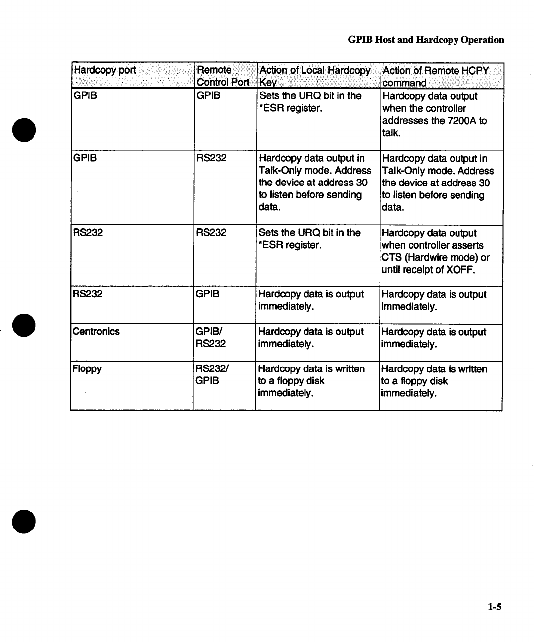
GPIB
GPIB
RS232
RS2.32
Centronics
Floppy
GPIB
RS232
RS232
GPIB
GPIB/
RS2.32
RS232/
GPIB
Sets the URQ bit in the
*ESR register.
Hardcopy data output in
Talk-Only mode. Address
the device at address 30
to listen before sending
data.
Sets the URQ bit in the
*ESR register.
Hardcopy data is output
immediately.
Hardcopy data is output
immediately.
Hardcopy data is written
to a floppy disk
immediately.
Hardcopy data output
when the controller
addresses the 7200A to
talk.
Hardcopy data output in
Talk-Only mode. Address
the device at address 30
to listen before sending
data.
Hardcopy data output
when controller asserts
CTS (Hardwire mode)
until receipt of XOFF.
Hardcopy data is output
immediately.
Hardcopy data is output
immediately.
Hardcopy data is written
to a floppy disk
immediately.
1=5

GPIB Device Interconnections
GPIB Device Interconnections
The devices on the GPIB network may be connected in any combination of star or linear ar-
rangements (Figure 1.1 ). Standard IEEE 488.2 cables must be used to connect all the de-
vices and total length must not exceed 20 meters. The devices must conform to these rules:
¯ At least half the devices on the network must be turned on.
¯ One network can connect no more than 15 devices (including the controller).
One device must be connected for every two meters of cable, assuming one
¯
device presents one standard device load. The 7200A’s GPIB connector is
located on its rear panel.
Each device must have a unique bus address.
¯
1-6
OL=VtC;E A
DL=VlCE D
DEVICE B
DEVICE B
DEVICE C
I I EC
STAR CONFIGURATION LINEAR CONFIGURATION
Figure 1.1 : Examples of GPIB Network Arrangements

RS-232-C Remote Control
The 7200A interface is defined by the following GPIB function codes:
For a description of these functions and their subsets, see IEEE Standard 488.1, Section 2.2 through 2.12.5. The
IEEE Standard is published by the Institute of Electrical and Electronics Engineers, Inc., 345 East 47th Street, New
York, New York 10017.
INTERFACE FUNCTION
Controller (CO)
Source Handshake (SH1)
Acceptor Handshake (AH1)
Talker (T6)
Listener (L4)
Service Request (SR1)
Device Trigger (DT1)
Device Clear (DC1)
Parallel Poll (PP0)
Remote Local (RL1)
Electrical Interface (E2.)
*Unaddress refers to the action taken when the interface switches its
function. This action effectively clears the current function before the
next function is selected.
Table 1.1: 7200 IEEE-488 Function Codes
RS-232-C Remote Control
No controller capability.
Complete source handshake capability.
Complete acceptor handshake capability
Basic talker with serial poll capability and
unaddress* if MLA (My Listen Address).
Basic listener with unaddress if MTA (My
Talk Address).
Complete serial poll capability.
Capable of responding to device trigger.
Responds to device clear (universal or
selective).
No parallel poll capability
Complete remote/local capability
SRQ, NRFD, and NDAC are tri-state lines
The 7200A can also be operated from a computer or terminal via its RS-232-C port. RS-232C uses serial transmission and complies with the Electronic Industries Association’s RS-232-
C standard. (The equivalent international standard is ISO V24 which is generally compatible
with the RS-232-C version.)
Unlike the GPIB where many devices can be interconnected, the RS-232-C connects just
two devices. Only three communication lines are necessary to establish the interface: trans-
mired data, received data, and logic ground. However, the additional lines, RTS (request to
send) and CTS (clear to send), permit transfer of data only after confirming that the receiving
1-7
RS-232-C Configuration
device is capable of accepting more data. That is, the sender sends an RTS and waits for a
CTS from the receiver before sending data. This protocol guarantees that data does not over-
run the receiver’s buffer.
RS-232-C offers compatability with most computers. It uses a bit-serial data format with a
maximum transmission rate of 19,200 bits per second, much less than that of GPIB.
Each data word is transmitted as a separate packet with its own start and stop markers, or
bits. The RS-232-C standard defines the electrical characteristics of these bits and the composition of each packet. Their composition and transmission rate must be the same for both
the device and the 7200A. The Communications Setup screen is used to select transmission
rate, error checking (parity), and number of stop bits. In order to establish communications,
additional serial transmission characteristics may be set remotely using the COMM_RS232
remote command. See Section 5: Communication Commands for a description of this command.
RS-232-C Configuration
Setup the Serial Port
The 7200A contains a 9-pin, male RS-232-C connector for serial communication with a
printer, terminal, or computer. To connect an RS-232-C line to the 7200A, use a female DB9-
D connector. If the computer has a DB25-D connector, use a DB9-D to DB25-D cable adapter. The optional CTS and RTS handshaking guarantees that data passed between a remote
computer and the 7200A will not overrun the 7200A or the computer’s RS-232-C buffer.
Select the desired settings for the interface using the Communications Setup screen:
1. From the Main Screen, press the Configure System softkey to display the Configure
System setup screen.
2. Then press the Communication Setup softkey to display the Communications Setup
screen.
RS-232-C Host lnterconnection
Although the RS-232-C standard defines signal lines and electrical characteristics, it does
not define mechanical characteristics. The 7200A RS-232-C output port is configured as an
RS-232-C Data Terminal Equipment so that data is sent from pin 2 and received on pin 3.
For remote operation, the RS-232-C port must be connected to a computer terminal.
The following diagrams are used for various host drivers.
1-8

RS-232-C Configuration
"Data Communication Equipment"
(7200A)
"Data Terminal Equipment"
Figure 1.2: RS-232-C Connection to an IBM-PC Host
DB9 to DB25 Wiring
This wiring configuration is used for IBM-PCs and compatibles with DB25-D connectors
configured as Data Terminal Equipment¯ Note that for XON-XOFF communication protocol,
only pins 2, 3, and 5 on the DB9-D connector are needed¯ Also, commercially available DB9to-DB25 adapter cables for the IBM-PC swap pins 2 and 3 and pins 7 and 8.
7200A
(DB9, DTE)
Pin 2
Pin 3
Pin 5
If Hardwaire handshaking is used (see "Communications Setup,
page 3-119"), the following connections must also be satisfied.
Pin 7
Pin 8
Computer
(DB25, DTE)
Tx Pin 2
Rx
Gnd
CTS
RTS Pin 4
Pin 3
Pin 7
Pin 5
1-9
RS-232-C Configuration
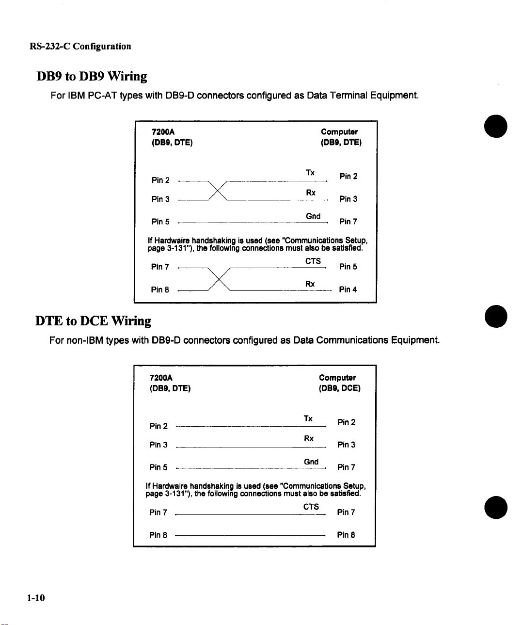
DB9 to DB9 Wiring
For IBM PC-AT types with DB9-D connectors configured as Data Terminal Equipment.
7200A Computer
(DE9, DTE) (DB9, DTE)
Pin 2
Pin 3 Pin 3
Pin 5
If Hardwaire handshaking is used (see "Communications Setup,
page 3-131"), the following connections must also be satisfied.
Pin 7
Pin 8 --~,
\/
Tx
Gnd
CTS
Rx
Pin 2
Pin 7
Pin 5
Pin 4
DTE to DCE Wiring
For non-IBM types with DB9-D connectors configured as Data Communications Equipment.
7200A Computer
(DB9, DTE) (DBg, DCE)
Pin 2
Pin 3 Pin 3
Tx
Rx
Pin 2
1-10
Pin 5
If Hardwaire handshaking is used (see "Communications Setup,
page 3-131"), the following connections must also be satisfied.
Pin 7
Pin 8 Pin 8
Gnd
CTS Pin 7
Pin 7

RS-232-C Configuration
RS-232-C Interconnections for Hardcopy
When connecting an RS-232-C serial printer/plotter to the 7200A, the printer/plotter configu-
ration must match the 7200A RS-232-C port settings. To modify settings, use the Communi-
cations Setup screen.
RS-232-C Connection
=Data Terminal Equipment"
=Data Communication Equipment"
(7200A)
Figure 1.3: RS-232-C Connection to an RS-232-C
Serial Plotter
DB9 to DB25 Wiring
NOTE: The 7200A RS-232-C interface is a DB9-D connector. Use
an adapter cable to connect to an RS-232-C DB25-D connector.
Pin2
Plot I
Pin4
Pin8
Pin8
PIn 7
~n2
~n8
~n7
Pin4.
Pin5
Pin6
Pin 20
Pin 8
1-11
RS-232-C Host Operation
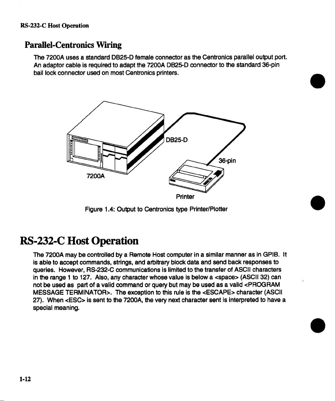
Parallel-Centronics Wiring
The 7200A uses a standard DB25-D female connector as the Centronics parallel output port.
An adaptor cable is required to adapt the 7200A DB25-D connector to the standard 36-pin
bail lock connector used on most Centronics printers.
7200A ~
Printer
Figure 1.4: Output to Centronics type Printer/Plotter
RS-232-C Host Operation
The 7200A may be controlled by a Remote Host computer in a similar manner as in GPIB. It
is able to accept commands, strings, and arbitrary block data and send back responses to
queries. However, RS-232-C communications is limited to the transfer of ASCII characters
in the range 1 to 127. Also, any character whose value is below a <space> (ASCII 32) can
not be used as part of a valid command or query but may be used as a valid <PROGRAM
MESSAGE TERMINATOR>. The exception to this rule is the <ESCAPE> character (ASCII
27). When <ESC> is sent to the 7200A, the very next character sent is interpreted to have
special meaning.
1-12
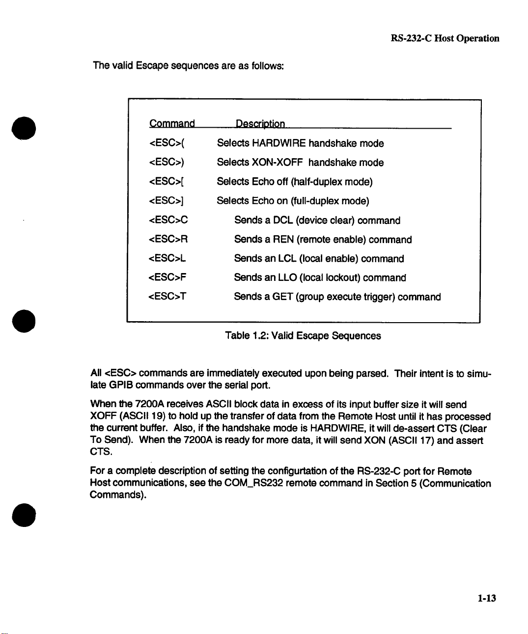
The valid Escape sequences are as follows:
RS-232-C Host Operation
Command
<ESC>(
<ESC>)
<ESC>[
<ESC>]
<ESC>C
<ESC>R
<ESC>L
<ESC>F
<ESC>T
All <ESC> commands are immediately executed upon being parsed. Their intent is to simulate GPIB commands over the serial port.
When the 7200A receives ASCII block data in excess of its input buffer size it will send
XOFF (ASCII 19) to hold up the transfer of data from the Remote Host until it has processed
the current buffer. Also, if the handshake mode is HARDWlRE, it will de-assert CTS (Clear
To Send). When the 7200A is ready for more data, it will send XON (ASCII 17) and assert
CTS.
Descriptiorl
Selects HARDWIRE handshake mode
Selects XON-XOFF handshake mode
Selects Echo off (half-duplex mode)
Selects Echo on (full-duplex mode)
Sends a DCL (device clear) command
Sends a REN (remote enable) command
Sends an LCL (local enable) command
Sends an LLO (local lockout) command
Sends a GET (group execute trigger) command
Table 1.2: Valid Escape Sequences
For a complete description of setting the configurtation of the RS-232-C port for Remote
Host communications, see the COM_RS232 remote command in Section 5 (Communication
Commands).
1-13

Section 2: Command S ntax
The following segments describe the rules and syntax for controlling the 7200A from a remote computer over either GPIB or RS-232-C. Any differences between the ports are noted.
Message Types
Commands
Responses
Waveforms
Status
With few exceptions, all commands, responses, and status messages are encoded accord-
ing to the American Standard Code for Information Interchange (ASCII) and are strings
printable characters. Upper and lower case characters are interchangeable.
Commands have two categories: action and query.
An action command causes the 7200A to make an assignment
or perform a function. For example, it might cause the 7200A to
calibrate all the plug-ins, or an assignment may result in a new
front panel setting, a communication parameter receiving a new
value, or the date being set.
Commands that request results are called queries. They ask the
7200A to return waveform data, settings, or measurements.
These are replies sent from the 7200A in response to query com-
mands.
Waveform data is a special form of response. It may be output in
binary or hexadecimal formatted blocks. These formats are more
compact than that used for response messages, so a large number of data points can be transferred in less time.
A status message indicates the 7200A’s current internal state.
2-1
Command Processing
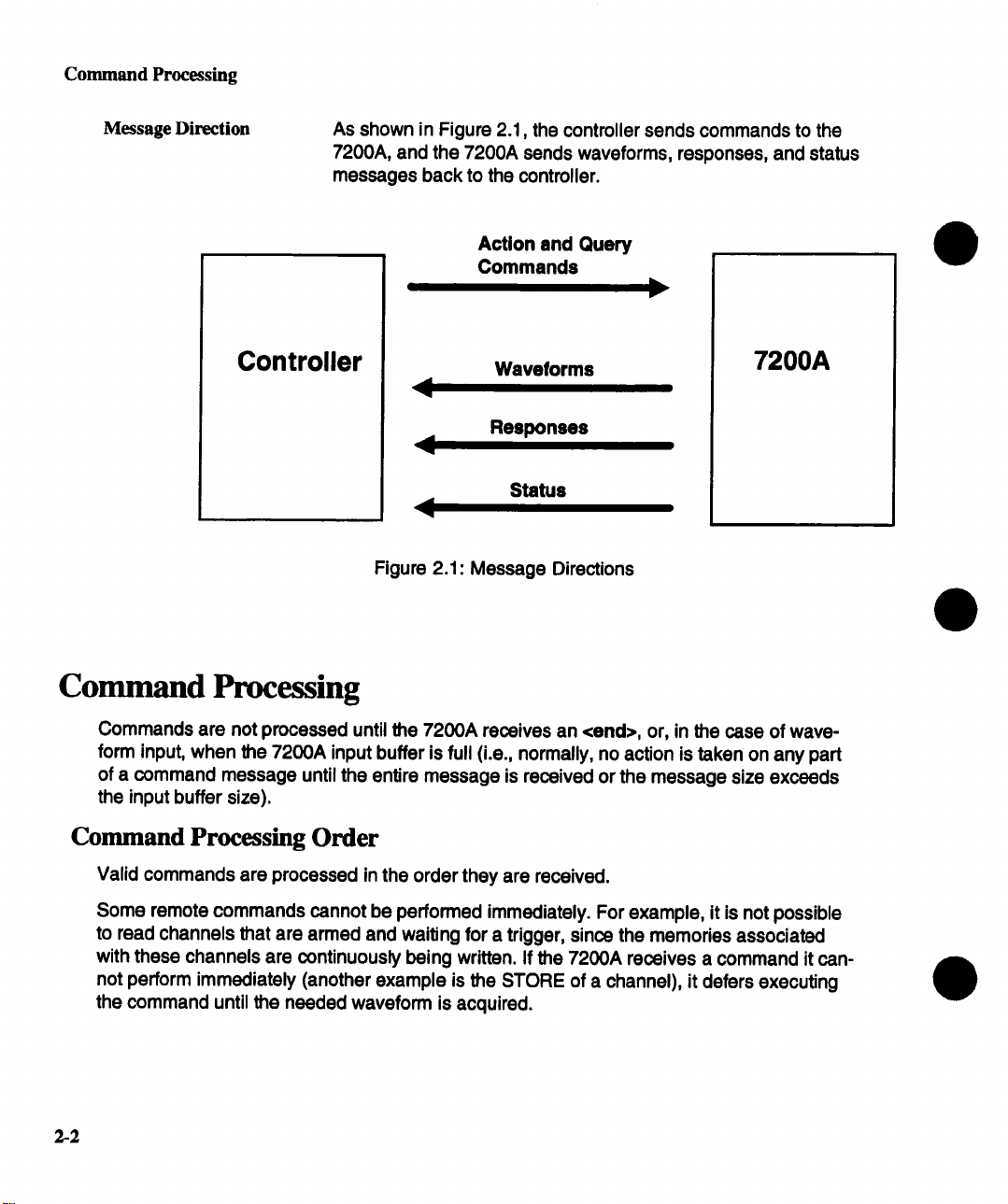
Message Direction
As shown in Figure 2.1, the controller sends commands to the
7200A, and the 7200A sends waveforms, responses, and status
messages back to the controller.
Controller
Action and Query
Commands
Waveforms
Responses
Status
Figure 2.1: Message Directions
7200A
Command Processing
Commands are not processed until the 7200A receives an <end>, or, in the case of waveform input, when the 7200A input buffer is full (i.e., normally, no action is taken on any part
of a command message until the entire message is received or the message size exceeds
the input buffer size).
Command Processing Order
Valid commands are processed in the order they are received.
Some remote commands cannot be performed immediately. For example, it is not possible
to read channels that are armed and waiting for a trigger, since the memories associated
with these channels are continuously being written. If the 7200A receives a command it cannot perform immediately (another example is the STORE of a channel), it defers executing
the command until the needed waveform is acquired.
2-2

IEEE-488 Standard Messages
Command Errors
Before attempting to execute a command or query, the 7200A confirms that all the required
parts of the command are provided, and that all the arguments are within required ranges.
If an error is generated, the 7200A will set the appropriate status and, if enabled, report it to
the host computer. The host can then interrogate the status byte(s) to determine the nature
of the error. Refer to Section 4 for details on status bytes.
NOTE: Commands preceding and following an error in
multi-command messages are still executed. This provides
consistent operation whether commands are sent one at a time or
several per message.
Output from the 7200A
When the 7200A generates a response to a query, the controller should read it before sending a second query. If the controller sends a second query before reading the response to
the first one, the 7200A interprets this as an Interrupted Action and performs the following:
1. Upon receiving the <end> of the second query, the 7200A flushes its output buffer of all responses to previous queries.
2. The 7200A sets a Query Error bit, and
3. The 7200A fills the output buffer with the response to the second query.
IEEE-488 Standard Messages
This section explains how the 7200A reacts to the Standard 488.2 messages.
NOTE: This section pertains to GPIB only
Serial Poll Function The 7200A implements a full Serial Poll Interface Function:
1. It can assert the SRQ (Service Request) control line.
2. It will respond with the current serial poll byte or STB when
addressed to Talk and after the Serial Poll Enable interface
message is received.
3. After transmitting its status message, the 7200A stops assert-
ing the SRQ line and clears its internal status byte.
Receiving the Trigger
Message
The 7200A responds to the Trigger message [Group Execute
Trigger (GET) or the *TRG command] by arming all plug-ins.
The trigger signal, also available on the rear panel, can be used
2-3

IEEE-488 Standard Messages
for external hardware or event synchronization to internal 7200A
operations. It is executed after all previously received commands
have been processed.
Interface Clear
Device Clear (Sdective
or Universal)
Go to Local, Go to Remote,
Go to Remote with
Lockout Local
The Interface Clear message (asserting IFC line) is an asynchronous control line that causes all bus activity to halt. When the
7200A receives the IFC message, it becomes unaddressed,
stops talking or listening, and will not participate in future bus
transactions until readdressed to talk or listen.
The 7200A will respond to a Selective Device Clear or a Univer-
sal Device Clear interface message. The former requires that the
7200A first be addressed to listen, followed by the Selective Device Clear message. The latter does not require that the instru-
ment be previously addressed to listen. Device Clear causes the
input buffer, the output queue, and the message available
(MAV) status bit to be cleared.
The 7200A can operate in Local or Remote mode. In Local
mode, all front panel controls are operational and commands
from the host computer will also be processed. In Remote mode,
the 7200A operates under computer control and no front panel
controls are operational except the Local softkey (if enabled).
(The 7200A always powers on in Local mode.)
NOTE: The 7200A processes all messages regardless of being
in Remote or Local modes.
The 7200A switches to Remote mode (with Local softkey enabled) when the 7200A receives the command "REM", or a com-
mand is sent with the REN line asserted. All instrument settings
remain unchanged during local-to-remote transitions. The lower
left part of the 7200A screen indicates that Remote mode is enabled and the Local softkey appears. No other front panel controis operate.
2.4
If the 7200A is under remote control and the Local softkey is
pressed, the instrument interrupts program control and returns to
local control. Data and/or settings can now be changed locally.
CAUTION: To prevent a transition back to local mode the 7200A
can be placed in a Local Lockout state using the "LLOK" command. in Local Lockout state, all front panel keys and knobs are

IEEE-488 Standard Messages
disabled. Once Remote with Local Lockout is set, it can only be
cleared when the 7200,4 is put into Local mode by sending the
=L OC" command or readdressing the 7200A with REN deas-
serted.
Message Syntax
Messages consist of one or more data bytes which are sent over the bus.
All messages sent to and received from the 7200A are formed of English words except for
waveform transfers. Abbreviations, typically two to four characters, are also defined to
achieve higher throughput. Lower or upper case alphabetic characters are interchangeable.
NOTE: Any message received by the 7200A must conform to IEEE-
488.2 syntactic requirements. (If a violation is detected, the 7200A
will generate an error which indicates an invalid command.) The
syntax for each type of message is described below.
Action Command Syntax
Commands are sent to the 7200A to initiate various actions. They contain Headers, sometimes an Argument(s), and a Terminator:
Header Identifies what action to take; e,g., set the date, stop acquisition.
Ar~nt(s)
Terminator
Qualifies or supplements the header. The argument acts as a parameter(s) or data to the header. It is included in the command
only if a header is defined to require an argument(s). For example, an argument indicates what date to set.
Indicates the end of the command message. GPIB and
RS-232-C have different message terminators. In this manual,
the command message terminator is represented by <end>.
2-5
IEEE-488 Standard Messages
r
Space
mnemonic ~j_
I
’ Long Form
mnemonic
, Short Form
I
HEADER
I
Figure 2.3: Action Command Syntax
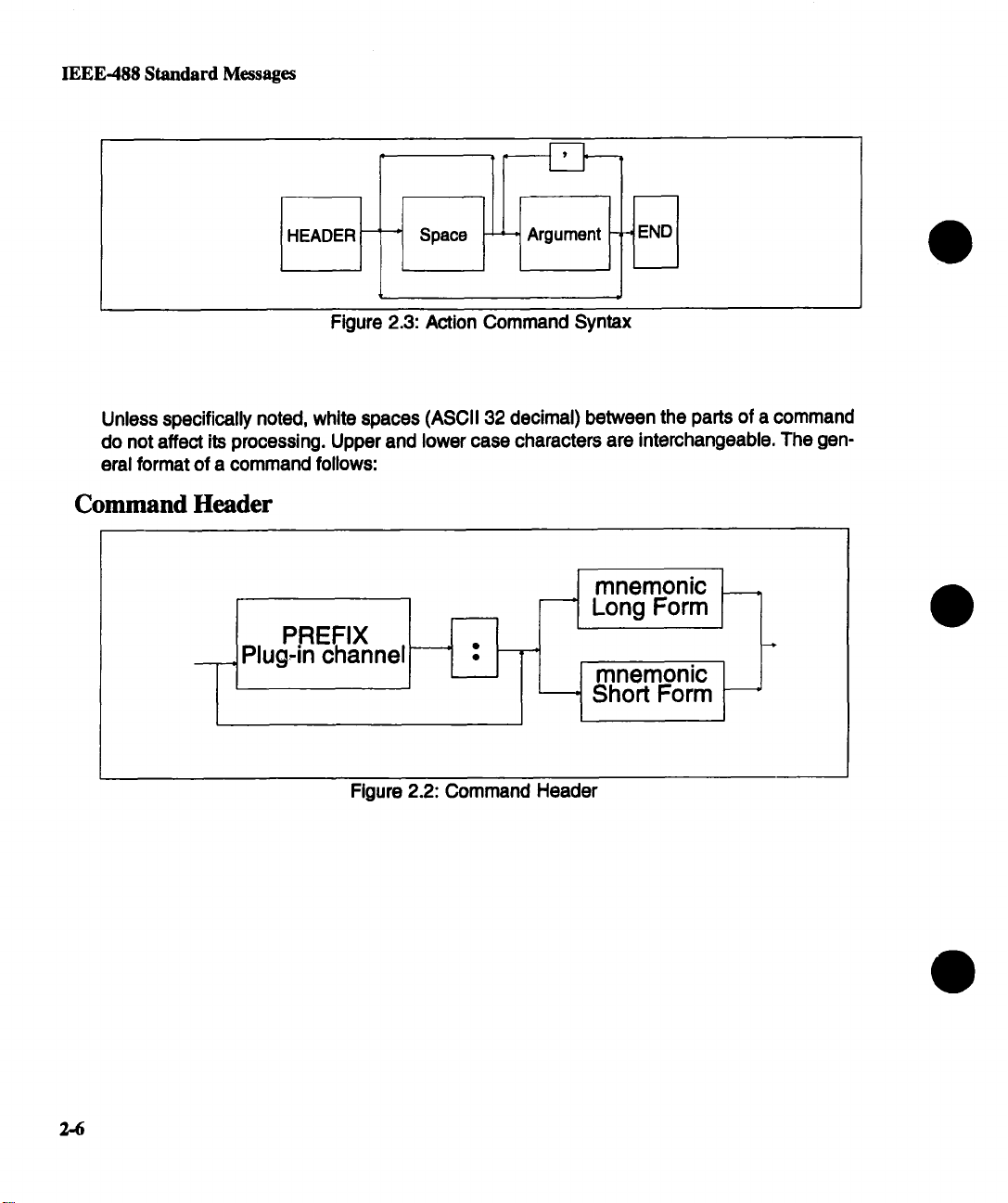
Unless specifically noted, white spaces (ASCII 32 decimal) between the parts of a command
do not affect its processing. Upper and lower case characters are interchangeable. The general format of a command follows:
Command Header
PREFIX I
Plug.in channel
I
2-6
Figure 2.2: Command Header

Command Arguments
IEEE-488 Standard Messages
--~ Numeric
~
’ ’ String ~
Figure 2.4: Command Arguments
Query Syntax
The Syntax of a Query is very similar to that of an Action command. A Query command adds
a question mark (=?") immediately after the last character of the header. For example, to find
the current value for the offset on channel 2 of plugin B, send: B2:OFFSET?.
NOTE:Many action commands have a corresponding query command which may have
arguments.
Figure 2.5: Query Syntax
2,-7

IEEE-488 Standard Messages
Multiple Commands
A message containing more than one command before the terminator is called a compound,
or multiple command message.
Sending a multiple command increases throughput. Each command (header and any arguments) is separated from the following one by a semicolon (";"). Space(s) on either side
the semicolon do not affect processing. Upper and lower case characters are interchangeable.
ACTION 1
j
COMMAND -
QUERY 1 "
COMMAND
Figure 2.6: Multiple Commands
A multiple command can include Action and Query commands. For example, one multiple
command can perform auto setup, request the current time and date being used, and execute a trigger command as follows:
ASET; DATE? ; *TRG <end>
2-8

IEEE-488 Standard Messages
Command Header
A command header defines the action to perform. The header begins with a letter and can
be followed by any combination of up to 15 letters, numbers, and underscores. Any com-
mand with more than four characters has a short form. (Long and Short form headers can be
intermixed.) Using the short form (four or less characters) increases throughput. The long
form, however, makes understanding program code easier. For example, to set the timebase
remotely, either TIME DIV or TDIV can be sent.
Command headers comprise three broad categories according to their syntactic make-up:
¯
Directed Header,
¯ System Header, and
¯ Standard Header.
Directed Header
This type of header directs an action at an object. The object can be either a plug-in, chan-
nel, trigger source, or trace. The prefix identifies the object being acted upon. It is followed
by a colon (=:") and the header which indicates the action performed.
prefix:header
Only one prefix is permitted per header.
NOTE: If a command is defined as having a prefix, the prefix must always be specified.
The types of prefixes are:
Mug.in The plug-in is identified by location. The mainframe plug-in slot
nearest the display is slot A. Slot B is to the right of A.
Use the plug-in prefix on/ywhen a command operates on the
plug-in controls, such as when setting the timebase. To set the
timebase to 5 msec per division for the plug-in in slot A, for example, use the command:
A:TIME_DIV 5ms
2-9

IEEE-488 Standard Messages
Channel
Source
The input channel is identified by its location in the plug-in. The
uppermost left BNC connector in plug-in A is labeled AI. The
next lower connector is A2, and so on. To modify all channels,
do not specify a specific channel.
Use the channel prefix only for commands which affect vertical
amplifiers, such as when setting the vertical sensitivity. To set
the vertical sensitivity to 5 mV per division for plug-in A, channel
1, for example, use the command:
A1 :VOLT_DIV 5mV
To set all of the plug-in’s channel settings to be the same, use
the plug-in prefix with no channel designation. For example, to
set offset to 10 mV for all channels, use the command:
A:OFST 10 mV
Since a rigger command can specify settings for each trigger
source, it must be specified as a prefix. The prefix symbols are
either:
An input channel as previously defined;
Plug-in and =EX" for the external trigger signal;
Plug-in and =EX10" for the external tdgger signal divided by
ten; or
Plug-in and =LINE" for triggering on the power line frequency.
2-10
Trace
To set the trigger level to 5 mV per division for the external trigger signal divided by ten, for example, use the command:
AEX10:TRIG_LEVEL 5mV
Traces 1 through 8, indicated as T1 through T8, define the processing and display characteristics of traces. For example, to
query the horizontal position of trace 7 use the command
T7:HOR_POSITION?

IEEE-488 Standard Messages
System Header
This type of header indicates an action that affects general oscilloscope operation; that is, an
operation not necessarily restricted to a particular plug-in, channel, or trace. Examples are
changing the grid selection and cursor type. The System Header format disallows a prefix.
For example, to turn on local display processing, use the command:
DISPLAY_ON
Standard Header
This type of header indicates a command that is explicitly required by the IEEE-4882 standard. These commands have the same format as the System Header, except an asterisk ("*")
immediately precedes the first letter of the command. For example, the *RST command initiates a device reset, *IDN? asks the device for its identification.
Command Argument(s)
A command argument(s) qualifies or supplements the header. It is included in the command
only if a command is defined to require an argument(s). For example, an argument indicates
what value to set for volts per division.
Most commands require one or more arguments to describe a desired action in detail (see
Figure 2.4). The first argument is separated from the header by one or more spaces. Argu-
ments are separated from each other by commas.
The possible types or arguments are:
Decimal Numeric Any number in numeric repesentations NR1, NR2, or NR3 as de-
fined by ANSI X3.42-1975. These refer to integers (e.g., -45),
floating point (e.g., 3.1443), or exponential values (e.g.,
3.1459E+00), respectively.
The ASCII characters "E" or "e" are used to delimit the mantissa
from the exponent in exponential arguments. Spaces are allowed between the exponential delimiter and the digits (0
through 9), but are not allowed between digits, or between the
decimal point (.) and the digits.
Numeric values with fractional parts must be expressed as a
floating point or an exponental value. For example, 3.14159 and
3.14159E+00 are both acceptable standard formats.
2-11

IEEE-488 Standard Messages
The allowable range depends on the command. If a numeric is
sent to the 7200A and has a precision greater than allowed, the
7200A will truncate, process the result, and generate a warning.
If a numeric not included in the specified set is sent, a valid numedc closest to that sent is used. For example, vertical position
must be specified with a value that is a multiple of 0.02. If 68.01
were sent, 68.00 is used.
Suffixes can replace exponential notation. For example, these
commands are equivalent:
TIME_DIV 5.00E-6
TIME_DIV 5.00 US
Valid suffixes are listed in the following table:
Allowed<Suffix Mult.>Mnemonics
Definition Mnemonics
1E18
EX
1E15 PE
1E12 T
1 E9 G
1 E6 MA
1E3 K
1E-3 M
1E-6
U
1E-9 N
1E-12
P
1E-15 F
1E-18 A
NOTE: Only engineering unit multipliers
are allowed.
Table t~cen from ANSI/tEEE SId 488,2-1987
Table 2.1: Valid Suffix Mnemonics
2-12
IEEE-488 Standard Messages
Non-Decimal
Numeric
String
Numbers can also be used in bases other than base 10. For example, each bit in a status byte may be understood better if the
byte is specified in hexadecimal or binary.
Precede non-decimal arguments with a pound sign ("#") followed by an "H" for hexadecimal, "Q" for octal, and "B" for bi-
nary. Note that numbers are treated as unsigned with an implicit
radix point. For example, #HFF and #B11111111 are both 255.
Some commands require or allow String arguments such as
"ON" or "OFF". These arguments contain 7-bit ASCII alphanu-
meric characters. A string begins with an alpha character which
may be followed by alphanumeric characters A through Z, a
through z, 0 through 9, and =._". Carriage return or line feeds are
not valid characters. Note that the oscilloscope treats upper and
lower case characters identically.
Each command definition specifies the maximum number of
characters for its string argument(s).
Quoted strings are delimited by either an apostrophe (’) or a quo-
tation mark (=). The 7200A returns quoted strings with quotation
marks. The same type of delimiter that opens a quoted string
must close it. Strings within strings are allowed as long as each
string has the same opening and closing delimiters.
Waveform Data
A quoted stdng may not be terminated with an <end> character.
For example, "test <end> is an invalid string.
The WAVEFORM command lets you send or read a complete
waveform. The waveform usually contains a very large amount
of data. Due to its length, a special formatting convention is used
to transfer the large data blocks. See page 2-17 "Waveform
Data Syntax" for an explanation of this format.
2-13
IEEE-488 Standard Messages
Keywords
Some commands have several arguments. For example, the command for configuring a
hardcopy device can have up to ten arguments that set such characteristics as plotter speed
and paper size. Rather than listing every argument when only a few need changing, the argu-
ment specified is identified by a =keyword".
A keyword is a character argument that must be followed by a comma, and then an associated value for the characteristic being set. The value may be one of the four types of arguments previously described.
Arguments not specified remain unaffected.
For example, the INTENSITY command is used to program the brightness of the traces and
grids independently. To set the grid’s intensity to half scale, send: INTENSITY GRID,,50. The
trace intensity remains unchanged.
For commands with several keywords, the order of the keyword-value pairs does not matter.
NOTE: A multi-argument command that does not use keywords
must have all its arguments listed, and ordered in the same sequence as shown in the command definition.
An example of a command with no keywords is the date command, which requires specifica-
tion of the day followed by the month, etc.
When querying most keyword commands, you can give the keyword(s) as an argument. For
example, CRST? HABS, VABS returns only the absolute horizontal and vertical cursor posi-
tions. If no argument is specified, all values are returned.
Command Terminators
Commands sent one at a time must end with a terminator. In this manual, terminators are indicated by <end>. Alternatively, multiple commands can be sent together by terminating
each command with a semicolon and terminating the entire multiple command message with
<end>.
GPIB Terminators
The only valid GPIB terminator is Eel (End or Identify) asserted with the last character sent.
This is necessary because of the possibility of binary data transmission into the 7200A
would make termination on a line feed alone impossible.
NOTE: The 7200A always terminates its response messages with a
line feed character with EOI asserted.
2-14

Response Syntax
RS-232-C Terminators
The COMM_RS232 command is used to define the <end> for command messages, and
separately for response messages.
The keyword El defines the <end> of command messages as a number from 1 through 127.
The default value is carriage return (decimal 13). If another value is selected, it must not
used elsewhere in the command argument; otherwise, the 7200A will prematurely terminate
the command.
The keyword EO defines the end of messages transmitted by the 7200A. The initial value is
CR LF (carriage return, then line feed).
For example, Arbitrary Block Program Data suitable for waveform transfers is sent as ASCII
alphanumeric characters between the range 0 through 9 and A through F. Therefore, select
a number that does not have a value corresponding to the ASCII decimal values of these al-
phanumeric characters.
Response Syntax
Query commands sent to the 7200A result in information being returned. The packet of re-
turned information is called a response message. This message typically contains measure-
ment results, settings, or status information. If multiple queries are sent in the same
command, the responses will be returned in one multi-response message with the individual
responses separated by semicolons (";").
The computer should completely read any responses from the 7200A before sending new
queries. If the computer sends a query command, starts reading the response, and issues
another command before completely reading the results of the first query, the 7200A interprets this as an interrupted action, sets the query error status bit, clears the output
queue,and sends the second response.
Responses conform to a general format, and with few exceptions are ASCII strings of print-
able characters. Generally, the syntax of any response is as follows:
2-15
Response Syntax
where
<header>
<argument data>
HEADER
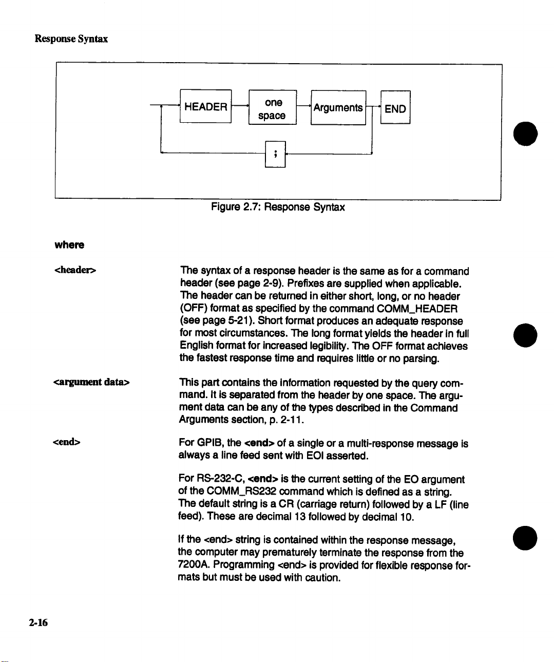
Figure 2.7: Response Syntax
The syntax of a response header is the same as for a command
header (see page 2-9). Prefixes are supplied when applicable.
The header can be retumed in either short, long, or no header
(OFF) format as specified by the command COMM_HEADER
(see page 5-21). Short format produces an adequate response
for most circumstances. The long format yields the header in full
English format for increased legibility. The OFF format achieves
the fastest response time and requires little or no parsing.
This part contains the information requested by the query com-
mand. It is separated from the header by one space. The argument data can be any of the types described in the Command
Arguments section, p. 2-11.
one
space
Arguments
2-16
<end>
For GPIB, the <end> of a single or a multi-response message is
always a line feed sent with EOI asserted.
For RS-232-C, <end> is the current setting of the EO argument
of the COMM_RS232 command which is defined as a string.
The default string is a CR (carriage return) followed by a LF (line
feed). These are decimal 13 followed by decimal 10.
If the <end> string is contained within the response message,
the computer may prematurely terminate the response from the
7200A. Programming <end> is provided for flexible response for-
mats but must be used with caution.
Waveform Data Syntax
If COMM_HEADER SHORT was sent before the following multi-response message:
T1 :HOR_POSlTION?; *STB?; T1 :VERT_POSrrlON?<end>
The response would be:
T1 :HPOS 1.0,1; *STB 48; VPOS 1.0<end>
Waveform Data Syntax
Waveform data is a specially formatted argument used to transfer large amounts of binary or
hexadecimal data. The WAVEFORM command uses this argument to send data to, or to
read data from the 7200A.
The 7200A supports three block data formats:
¯ Definite length arbitrary block data,
¯ Indefinite length arbitrary block data, and
¯ "OFF".
The COMM_FORMAT command (see page 5-19) is used to select the desired format.
Waveform Data transfers are used by the 7200A to send waveforms to a host controller. The
waveform query will be used in this section to describe the waveform data response format.
The WF? waveform query may optionally be followed by ALL, DESC, TEXT, DAT1, and
DAT2 to query specific parts of the waveform. If nothing follows the WF?, then ALL is as-
sumed.
Data Element Format
Each waveform point is called a data element. Using two commands, COMM_FORMAT and
COMM_ORDER, the 7200A supports several methods of forming data elements. You can
specify:
¯ the size or the width of the data element (i.e., the number of bytes),
¯ how it is encoded (i.e., binary or hexadecimal) and
¯ the arrangement of bytes for multi-byte words.
2-17
Waveform Data Syntax
Data Width
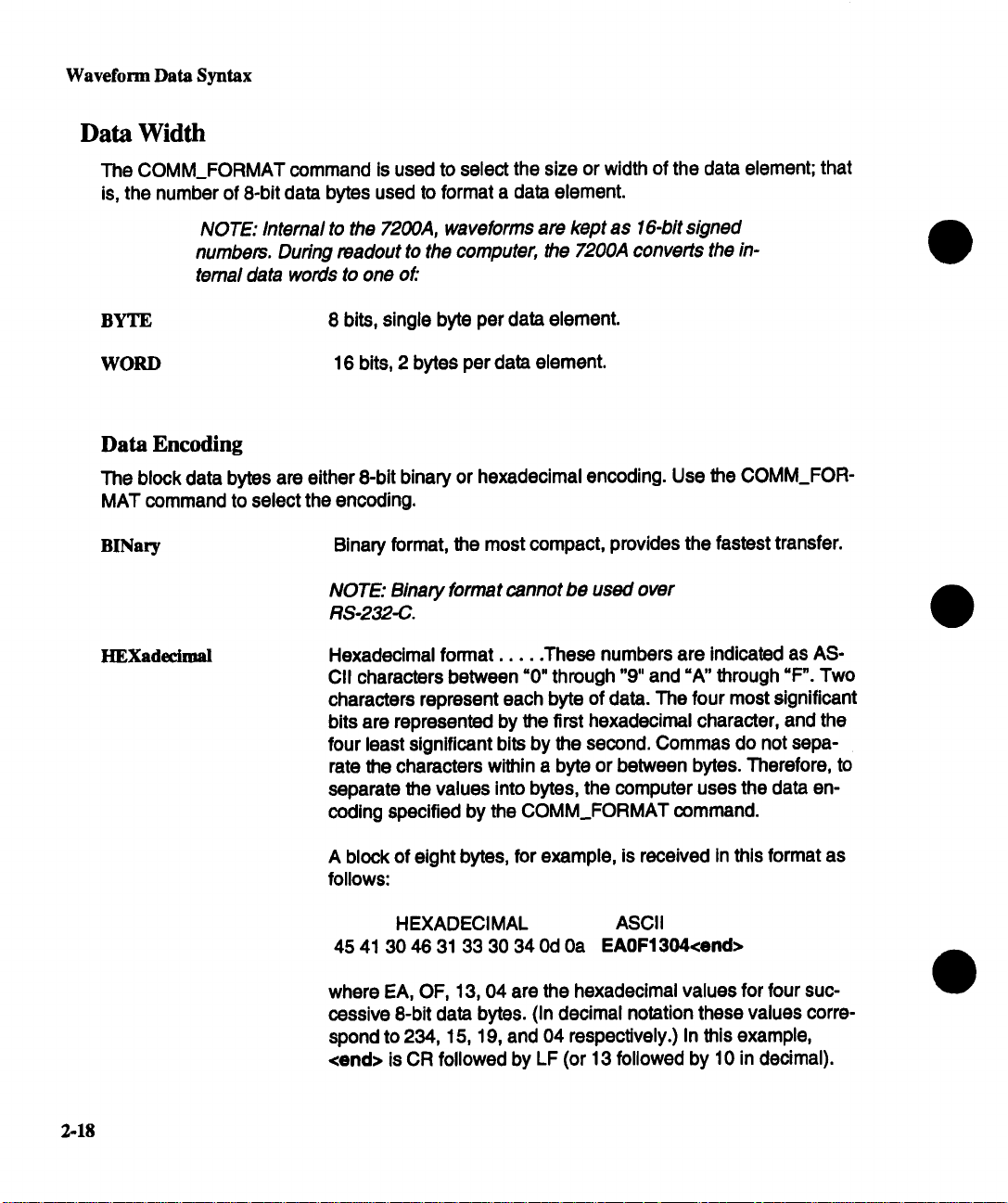
The COMM_FORMAT command is used to select the size or width of the data element; that
is, the number of 8-bit data bytes used to format a data element.
NOTE: Internal to the 7200A, waveforms are kept as 16-bit signed
numbers. During readout to the computer, the 7200,4 converts the intemal data words to one of."
BYTE
WORD
Data Encoding
The block data bytes are either O-bit binary or hexadecimal encoding. Use the COMM_FORMAT command to select the encoding.
BINary Binary format, the most compact, provides the fastest transfer.
HEXadecimal
8 bits, single byte per data element.
16 bits, 2 bytes per data element.
NOTE: Binary format cannot be used over
RS-232-C.
Hexadecimal format ..... These numbers are indicated as AS-
CII characters between =0" through "9" and =A" through =F". Two
characters represent each byte of data. The four most significant
bits are represented by the first hexadecimal character, and the
four least significant bits by the second. Commas do not sepa-
rate the characters within a byte or between bytes. Therefore, to
separate the values into bytes, the computer uses the data encoding specified by the COMM_FORMAT command.
A block of eight bytes, for example, is received in this format as
follows:
2-18
HEXADECIMAL
45 41 30 46 31 33 30 34 0d 0a EAOF1304<end>
where EA, OF, 13, 04 are the hexadecimal values for four successive 8-bit data bytes. (In decimal notation these values correspond to 234, 15, 19, and 04 respectively.) In this example,
<end> is CR followed by LF (or 13 followed by 10 in decimal).
ASCII

Waveform Data Syntax
Byte Order
When the width of the data is words, the order or sequence in which the bytes are sent can
be selected using the COMM_ORDER command:
HI
The most significant byte is sent first, the least significant is sent
last. This format is generally known as the Motorola format since
the most significant byte is at a lower address.
LO
The least significant byte is sent first, the most significant is sent
last. The LO format is known as the Intel (or Zilog) format since
the least significant byte is at a lower address.
Definite length arbitrary block data
This format is used for sending blocks of previously fixed sizes. It is selected with the
COMM FORMAT DEF9 comand:
#9nnnnnnnnn<DB1xDB2>,.,<DBX>
where nnnnnnnnn is a decimal integer defined by nine bytes and is used to define the number of data bytes.
<DBI>,<DB2> .....
In this format, a block of four bytes, for example, is sent or received
as follows:
#9000000004<DBI><DB2<DB3><DB4>
This format begins with a pound sign (=#") followed by a =9", then 9 bytes (which when taken
together form a decimal integer equal to the number of 8-bit data bytes to follow), and the
four 8-bit data bytes.
If the waveform data is the last command of the message response, the command termina-
tor follows the waveform data. (The integer following =#9" does not count this terminator); oth-
erwise, it is separated from the next command or response by a semicolon.
<DBX> are 8-bit data bytes.
Indefinite length arbitrary block data
This format is used to send blocks of unspecified length. It is selected with the
COMM_FORMAT IND0 command:
#0<DBI><DB2>...<DBX><end>
where <end> is a previously defined message terminator.
2-19

Waveform Data Syntax
The format begins with a pound sign (=#") followed by a ~0", 8-bit data bytes, and the message terminator.
Note that since the number of bytes is not known and the data is binary,it would not be possible to separate it from another command or response and therefore MUSTbe followed by
<end>.
If the WF? is sent as a compound string with queries following it (i.e., T1 :WF?;T2:TRACE?),
the query error bit will be set and any queries following the WF? will be ignored. The response message will contain any responses to queries preceding WF? followed by the re-
sponse to WF?
OFF Format
Some computer languages make it difficult to check a few bytes/characters before receiving
the remainder of a data block. Therefore, the 7200A has the =OFF" format which is an exten-
sion of IEEE Standard 488.2.
The OFF format is nearly Identical to #0 indefinite format, except that it supresses the #0,
keywords normally included in the response, and comma separators. It is selected with the
COMM_FORMAT OFF command.
When OFF format is specified, the 7200A returns a data block having the format:
<DBI><DB2>...<DBX><END>
As with the #0 format above, the OFF block must be terminated with <end>.
NOTE: When writing waveforms back to the scope, the only accepted formats are #0 and #9, and the descriptor must be sent with
the data.
Example: Given that Trace 1 consists of a 338 byte descriptor and 1000 bytes for data
array 1, if the block format is OFF, COMM_HEADER is OFF, and the 7200A is sent the
query:
T1 :WF?<end>
the 7200A response would consist of 338 bytes for the descriptor plus 1000 bytes for the
wave array:
<338 byte DESCRIPTOR><DB339><DB340>...<DB1337><DB1338><end>
which is all data. Note, however, if the header was short or long, the prefix followed by the
alias or command name, respectively, would preceed the data.
2-20

Waveform Data Syntax
To write this data back to the 7200A, precede it with the command header (’1"1 :WAVE-
FORM), its keyword (ALL), comma, and #0 pdor to transmitting the data:
T1 :WAVEFORM ALL,#0<338 byte DESCRIPTOR> <DB339>
<DB340>...<DB1337><DB1338><end>
Altematively, the #9 format may be used:
T1 :WAVEFORM ALL,#9000001338<338 byte DESCRIPTOR> <DB339> <DB340>
.... <DB1337><DB1338><end>
RS-232-C Output Format
Waveform data over GPIB can be encoded in either binary or hexadecimal (see
COMM_FORMAT command). However, over RS-232-C the data encoding must be set to
HEX.
To format the appearance of the waveform data while pdnting on an RS-232-C device, use
the COMM_RS232 command to specify the maximum number of characters per line. The
keyword, LL, followed by a # specifies the maximum line length. After the end of each line,
the designated line separator character is inserted. This character is defined by the keyword
LS in the COMM_RS232 command.
For the count in the Definite length arbitrary block data, the line separator is not counted.
Also, for block data sent to the 7200A, LS is ignored.
For example, the response to the query T1 :WAVEFORM? DAT1 can be a block of 32 bytes
of data received from the 7200A’s RS-232-C host port. It is received in definite length arbitrary block format in hexadecimal encoding (required for RS-232-C):
TI:WAVEFORM DAT1,#90000000321234567890123456<Line_Separator>
DC78EF87DFOC128A<Line_Separator><end>
The =#9000000032" indicates the format ("#9") and the number of bytes sent (32 bytes
cluding the LS and the <end>). Note that HEX format doubles the number of binary bytes
representing the waveform. In this example, 32 HEX bytes bytes are transferred but really
represent 16 8-bit bytes of trace 1 (i.e., "1", "2" represents 12 base 16 or 18 decimal). Note
also that the waveform preamble (T1 :WAVEFORM DAT1 ,#9000000032) is ALWAYS ASCII.
This is always true if the data encoding is HEX or BINary. Also note that the line length (LL)
is 44 characters per line. When the <end> is reached before the LL is reached, an LS is sent
before <end> is sent.
2-21

Section 3: Waveform Transfer
Waveforms can be transferred between the 7200A and an external device via GPIB, RS-232C, or MSDOS format 3-1/2" floppy disk. All types of transmission use the same format for the
waveform. It is therefore possible, for example, to read a waveform out of the 7200A over
GPIB, direct the output into a file on an MSDOS floppy, and then recall the waveform from
the floppy to a memory in the 7200A.
Over GPIB or RS-232-C, the WAVEFORM remote command transfers a binary waveform from
an external device into the 7200A. The WAVEFORM? query transfers a binary waveform from
the 7200A to an external device. The COMM_FORMAT and COMM_ORDER remote com-
mands select the data point format to be used by the 7200A when it produces waveforms in
response to a WAVEFORM? query. The INSPECT?. query transfers an ASCII waveform from
the 7200A to an external device.
Waveform transfer via floppy disk does not require remote programming, but may be accom-
plished with STORE and RECALL front panel operations. Remote commands
STORE_SETUP, STORE, RECALL_SETUP, and RECALL may also be used to effect the store
and recall operations if desired.
Waveform Template
Waveforms produced by the 7200A contain, in addition to the actual data points, further information necessary to correctly interpret the data. This information includes the real time between data points, trigger offset, vertical gain and offset, acquisition time and plugin, etc. To
save space and increase the waveform transfer rate, all numerical values in the waveform are
binary.
The data and associated information are organized in a specific format described by the
waveform template. The template describes the size and location of each element in the
waveform. It may be obtained via GPIB or RS-232-C with the TEMPLATE? query. The tem-
plate is simply an ASCII file and may be examined with any text editor. See page 3-9 for a listing of the 7200A waveform template. On each line of the template, text following a ; is
commentary.
In addition to providing a description of the waveform structure to users who wish to interpret
waveforms obtained from the 7200A, the template also allows waveforms to be transferred between different LeCroy instruments and different versions of the same instrument. Waveform
transferral between different LeCroy instruments may be accomplished by sending not only
the waveform, but also the template according to which it was created, to the destination
instrument. The destination instrument interprets the waveform data according to the associated template and translates it into its own format.
3-1
Waveform Template
As an alternative to using the template to interpret a waveform, the INSPECT? query may be
used to obtain a nicely formatted and labeled ASCII representation of the waveform.
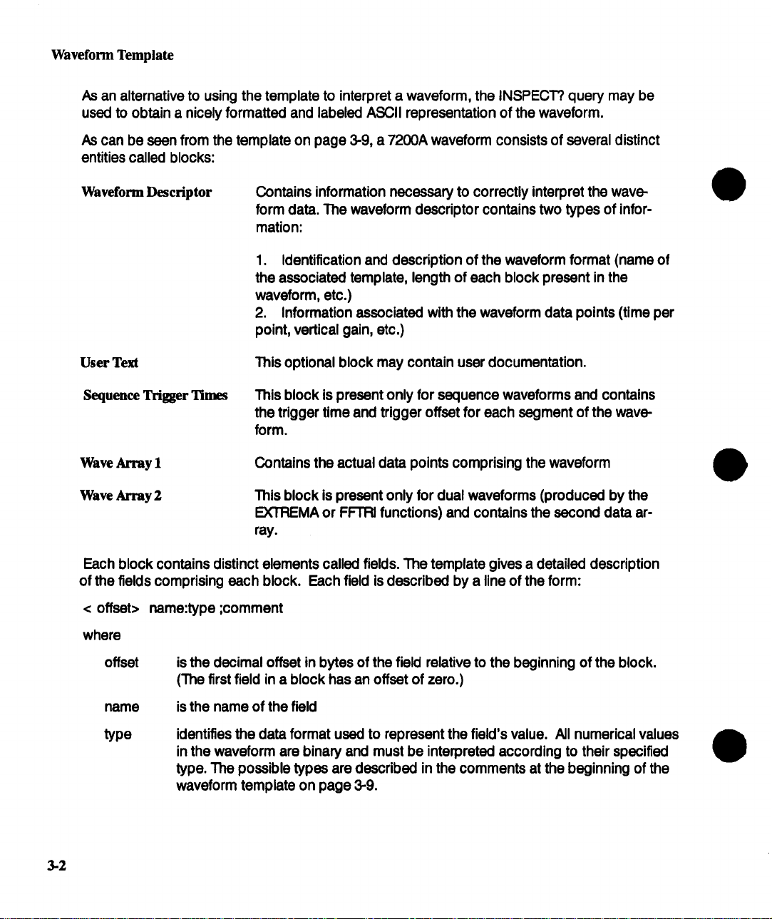
As can be seen from the template on page 3-9, a 7200A waveform consists of several distinct
entities called blocks:
Waveform Descriptor Contains information necessary to correctly interpret the wave-
form data. The waveform descriptor contains two types of information:
1. Identification and description of the waveform format (name of
the associated template, length of each block present in the
waveform, etc.)
2. Information associated with the waveform data points (time per
point, vertical gain, etc.)
User Text
Sequence Trigger Times
Wave Array 1
Wave Array 2
Each block contains distinct elements called fields. The template gives a detailed description
of the fields comprising each block. Each field is described by a line of the form:
< offset>
where
offset
name
type
name:type ;comment
is the decimal offset in bytes of the field relative to the beginning of the block.
(The first field in a block has an offset of zero.)
is the name of the field
identifies the data format used to represent the field’s value. All numerical values
in the waveform are binary and must be interpreted according to their specified
type. The possible types are described in the comments at the beginning of the
waveform template on page 3-9.
This optional block may contain user documentation.
This block is present only for sequence waveforms and contains
the trigger time and trigger offset for each segment of the waveform.
Contains the actual data points comprising the waveform
This block is present only for dual waveforms (produced by the
EXTREMA or FFTRI functions) and contains the second data ar-
ray.
3-2

Interpreting A Waveform
For example, refer to page 3-11 of the waveform template. The value of the vertical gain is
contained in the field named VERTICAL_GAIN, which is located 120 bytes from the start of
the waveform descriptor block and is represented as a 32-bit IEEE format single precision
floating point number.
Interpreting A Waveform
On page 3-4 is a hexadecimal/ASCII dump of an example waveform produced by the 7200A
in response to a WAVEFORM? query. The waveform descriptor block is located at the begin-
ning of the waveform and starts with the character string WAVEDESC. This is followed by the
character string name of the template which describes the waveform’s organization. For the
example waveform, the template name is LECROY_I_0".
To find the value of a field in the waveform descriptor, first find its offset and type in the tem-
plate. The offset specifies where to find the value in the waveform itself, and the type specifies
the size of the value and how to interpret it. Then retrieve the value from the waveform and interpret it according to its type.
The byte order must also be known in order to correctly interpret numerical values. Two alter-
nate byte orders are possible:
most significant byte .. least significant byte (Motorola format) or,
least significant byte .. most significant byte (Intel format).
The byte order of the waveform is specified by the COMM_ORDER field in the waveform descriptor. According to page 3-10 of the template, COMM_ORDER is a 16-bit value (type
enum) located at offset 34 from the start of the waveform descriptor block. Because the
waveform descriptor is the first block in the waveform, COMM_ORDER is the 16-bit value located at offset 34 from the start of the waveform. This value is 0000(16) or 0(lO). The descrip-
tion of the COMM_ORDER field in the template indicates that value 0 is the code meaning
HIFIRST. This specifies the byte ordering of all numerical values in the waveform to be
most significant byte .. least significant byte.
Once the byte order is known, any field in the waveform descriptor can be interpreted from its
offset and type specified in the template. For example, the field NOMINAL_BITS is repre-
sented as a 16-bit value (type word) located at offset 132 from the start of the waveform de-
scriptor. The 16-bit value located at offset 132 with byte ordering most significant ... least
significant is 0008(lS). Interpreting these 16 bits as a 2’s complement signed number (as
specified by type word) yields 8.
3-3

Interpreting A Waveform
OFFSET HEXADECIMAL
300000
300016
300032
300048
000064
000080
000096
000112
000128
000144
000160
000176
000192
000208
000224
000240
D00256
D00272
D00288
000304
300320
300336
300352
300368
300384
;000400
000416
000432
000448
000464
000480
000496
000512
000528
000544
57 41 56 45 44 45 53 43 O0 O0 O0 O0 O0 O0 O0 O0
4c 45 43 52 4f 59 5f 31 5f 30 O0 O0 O0 O0 O0 O0
O00l O0 O0 O0 O00l 38 O0 O0 O0 O0 O0 O0 O0 20
O0 O0 O0 36 O0 O0 O0 O0 4C 65 43 72 6f 79 20 37
O0 O0 O0 O0 O0 O0 O0 O0 O0 O0 ic 20 54 72 61 63
65 31 O0 O0 O0 O0 O0 O0 O0 O0 O0 O0 O0 O0 O0 68
O0 O0 O0 64 O0 O0 O0 O0 O0 O0 O0 67 O0 O0 O0 02
O0 O0 O0 02 O0 O0 O00l 38 80 O0 O0 O0 O0 O0 O0
7f O0 80 O0 O0 08 30 89 70 5f be 5b 79 08 ae O0
O0 O0 be 5a d7 f2 8e O0 O0 O0 56 O0 O0 O0 O0 O0
O0 O0 O0 O0 O0 O0 O0 O0 O0 O0 O0 O0 O0 O0 O0 O0
O0 O0 O0 O0 O0 O0 O0 O0 O0 O0 O0 O0 O0 O0 O0 O0
O0 O0 O0 O0 O0 O0 O0 O0 O0 O0 53 O0 O0 O0 O0 O0
O0 O0 O0 O0 O0 O0 O0 O0 O0 O0 O0 O0 O0 O0 O0 O0
O0 O0 O0 O0 O0 O0 O0 O0 O0 O0 O0 O0 O0 O0 O0 O0
O0 O0 O0 O0 O0 O0 O0 O0 O0 O0 40 08 3d 70 a3 d7
Oa 3d 33 09 01 01 07 c5 le ea O0 O0 O0 O0 O0 O0
O0 O0 O00b O0 O0 3f 80 O0 O0 O0 11 O0 O0 3f 80
O0 O0 O0 O0 O0 O0 O0 02 O0 01 O0 O0 O0 03 O0 O0
O0 O0 O0 O0 O0 O0 O0 O0 O0 O0 O0 O0 O0 O0 O0 O0
be 5b 79 08 ae O0 O0 O0 3f Oe 77 a9 Of 40 O0 O0
be 5b cl a7 72 O0 O0 O0 ba c2 bb d4 bb cc bb dO
bb c2 hb ce bb ca bb ce ]3]3 cc bb cc ba ba bb cc
bb ca bc ba bb bc hb ca bc dO bc dO bb c8 cO Oa
c3 30 c9 c2 cf Oe d9 b8 e3 04 ef Oe f8 3c 02 16
Ob 32 15 a2 19 70 20 4a 27 2e 29 e4 2b 5c 2f 06
2f e6 2d be 2d fa 30 76 2e 50 2f 26 2e la 2f 56
2e 34 2f 3c 2e le 2f 4c 30 4a 32 36 32 72 34 9a
bc f4 bb be bc f6 hb bc bc e8 bb cc bc d6 bb bc
bc e8 bb cc bc d6 bb bc bc e8 bb cc bc d6 bc ce
bd fa bc de be e8 bf O0 c4 68 c9 86 dl f8 d9 da
e4 84 ed cc f8 ea 02 2a Ob 06 13 Oc id 94 20 26
28 04 2a b4 2c 94 2d 92 31 6e 30 22 2f 02 2f 14
2f 74 2f 5c 2f 46 2e 32 2e 36 2f 44 30 3c 30 58
32 6e 31 64 34 62 33 90
ASCII
~AVEDESC ........
LECROY_I_0 ......
°°°°°°°8°°°° ....
...6 ....LeCroy 7
200 DSO ..... Trac
el .............h
¯..d .......g ....
°°°°°°°°8°°°.°°°
...... 0op o [y. o o
¯..Z ......V .....
o, oo* o°o oo, oo ¯ oo
.... o °o. oo ¯ , ° . , o
¯ ¯ ° ,o o. ¯ ..moo o,.
.... o oo °., , oo o ,.
o , oo o .o o oo o oo o . o
.......... 8.--p..
.-~3.. °o , ,°o . o ° . o
...... ? .......?.
....... o o oo o° ooo
¯ ¯ ,o ¯ o, ¯ .oo ¯ o. o.
¯ [y .....
. [oorooo ooo ooo,.
, o.o° o ..... o o . o,
... o o oo ooo o oo, oo
.0°oo.oo.°o., o oo
?.w..@..
.2...p J’.),+\/..
/. -. -. 0v.P/&.../V
¯ 4/../LOJ262r4..
. ¯ ¯ * ¯ *o * o. ¯ * ¯ o o o
.* ¯ oo °o . .** o. o .o
¯ ..o.o. * oho o.. oo
o o oo o oo*oo .,o..
¯
- .1nO"/./.¯
o ¯ ¯
It/\ IF. 2.61DOX
2nld4b3.
3-4
Figure 3.1: Hexadecimal/ASCII dump of a waveform

Interpreting A Waveform
Retrieving the data points of a waveform requires several steps:
1. Locate the start of the data In the waveform
To locate the beginning of wave array 1 in the waveform, add up the lengths of the blocks
which precede it" waveform descriptor, user text, and sequence trigger times.
Page 3-10 of the template specifies that the length in bytes of the waveform descriptor
block is contained in the field named WAVE_DESCRIPTOR, which is a 32-bit value (type
long) located at offset 36 from the start of the waveform descriptor block. For the example,
the 32-bit value located at offset 36 from the start of the waveform descriptor block
(which is the first block in the waveform) is (00000138)16, or (312)1o. Since the value of the
WAVE_DESCRIPTOR field is (312)1o, the waveform descriptor block is (312)10 bytes long.
Page 3-10 of the template specifies that the length in bytes of the user text block
is contained in the field named USER_TEXT, which is a 32-bit value located at offset
40 from the start of the waveform descriptor block. For the example waveform, the field
USER_’I--P_XT in the waveform descriptor is 0. This means that the user text is not present
in this waveform. Similarly, for the example waveform the sequence trigger time array
(TRIGTIME_ARRAY) is 32 bytes long.
For the example waveform, the data array (wave array 1) starts at offset
312 + 0 + 32 = 344 from the beginning ofthe waveform.
2. Determine the number of data points presenL
The total number of points in the data array is specified by the WAVE_ARRAY_COUNT field
in the waveform descriptor. Page 3-11 of the template indicates that this field is a 32-bit
value located at offset (92)10. For the example waveform, WAVE_ARRAY_COUNT has the
value of (00000068)16 or (104)1o.
Not every point in the data array may be valid, however. For example, if the waveform
corresponds to a horizontally repositioned trace it may be missing some points off one end.
The FIRST_VALID_PNT and LAST_VALID_PNT fields in the waveform descriptor give the
indices (starting from 0) of the first and last valid data points in the data array.
FIRST_VALID_PNT and LAST_VALID_PNT are 32-bit values located at offsets (100)1o and
(104)1o respectively. For the example waveform, FIRST_VALID PNT is 0 and
LAST_VALID_PNT is (000(X)067)16 or (103)10. Because WAVEARRAY_COUNT
(LastValid_Point - First_Valid_Point + 1), every point in the data array must be valid for
this particular waveform.
3. Determine the format or representation of each data point.
According to page 3-16 of the template, WAVE_ARRAY_I consists of an array of
measurement values or data points whose data format is described by the COMM_TYPE
field in the waveform descriptor block.
3-5

Interpreting A Waveform
The COMM_TYPE field specifies the size and type of data representation of each data
point.
Page 3-10 of the template specifies that the COMM_’I’YPE field is a 16-bit value
(type enum), located at offset 32 within the waveform descriptor. For the example
waveform, the COMM_TYPE field has the value 1. The description of the COMM_TYPE
field in the template indicates that value 1 is the code meaning word. This specifies that
each point in the data array is of type word, which is a 16-bit 2’s complement signed data
representation.
The first three (unscaled) points of the data array of the example waveform are (BAC2)16,
(BBD4)Is, and (BBCC)16 or (-17726)IO, (-17452)1o, and (-17460)Io.
Scale each data point value.
1
Further information in the waveform descriptor is used to correctly scale the vertical
magnitude of each point in the data array.
The units of the vertical value are given by the VERTUNIT field of the waveform descriptor,
which is an ASCII character string located at offset 154. For the example waveform, the
vertical units are V, or volts.
The vertical value Vii] of each data point i is given by the following equation:
Vii] = data[i] * VER’nCAL_GAIN- VERTICAL_OFFSET
3.6
where data[i] is the ith point in the data array, and VERTICAL_GAIN and
VERTICAL_OFFSET are fields in the waveform descriptor.
Page 3-11 of the template indicates that VERTICAL_GAIN and VERTICAL_OFFSET are
32-bit IEEE format floating point values located at offsets 120 and 124, respectively. For
the example waveform, the VERTICAL_GAIN is (38800000)16, which corresponds to the
value (6.1 E-5)1o. The VERTICAL_OFFSET Is
Determine the horizontal coordinate of each data point.
.
The units of the horizontal coordinate are given by the HORUNIT field of the waveform
descriptor, which is an ASCII character string located at offset 202. For the example
waveform, the horizontal units are s, or seconds.
The horizontal coordinate of each data point depends on whether or not the waveform is
a sequence waveform. This can be determined from the NOM-SUBARRAY_CNT field in
the waveform descriptor, which specifies the nominal number of segments in the waveform.
If NOM_SUBARRAY_CNT is greater than 1, the waveform is a sequence waveform.
NOM_SUB ARRAY_CNT is a 32-bit value (type long) located at offset 112. For the sample
waveform, NOM_SUBARRAY_CNT has the value 2. Thus the waveform is a sequence
waveform.

Interpreting A Waveform
5.1. Non-Sequence Waveforms
The horizontal coordinate T[i] of data point i is given by the following equation:
T[i] = i * HORIZ_INTERVAL + HORIZ_OFFSET
where i = 0..(WAVE_ARRAY_COUNT-I)
HORIZ_INTERVAL and HORIZ_OFFSET are fields in the waveform descriptor.
For time-domain waveforms, HORIZ_OFFSET is the time in seconds from the trigger to the
first data point (it may be negative) and HORIZ_INTERVAL is the time between data points,
or the sampling interval. The horizontal coordinate T[i] is thus the time relative to trigger
of data point i.
For frequency-domain or histogram waveforms, the above equation will yield the
horizontal coordinate T[i] as absolute frequency or bin location, respectively, with units
given by the HORUNIT field.
5.2. Sequence Waveforms
Sequence waveforms are composed of several consecutive segments, each of which has
its own trigger time and trigger offset. The wave array block of sequence waveforms
contains all the segments. The actual number of segments present is given by the
SUBARRAY_COUNT field in the waveform descriptor. Note that the actual number of
segments present may be less than or equal to the nominal number given by
NOM_SUBARRAY_CNT. The number of data points in each segment can be calculated
as follows:
Data points per segment = WAVE_ARRAY_COUNT/NOM_SUBARRAY_CNT.
Sequence waveforms contain a sequence trigger time block which is an array of trigger
time and trigger offset for each segment. Page 3-16 of the template describes the
sequence trigger time block. The block structure contains two fields, the TRIGGER_TIME
and the TRIGGER_OFFSET. In the waveform, these two fields are repeated for each
segment to comprise the sequence trigger time block.
For each segment, the corresponding TRIGGER_TIME field in the sequence trigger time
block contains the time in seconds between the trigger of the first segment and the trigger
of the current segment. (The time of the first trigger is given by the TRIGGER_TIME field
in the waveform descriptor). The TRIGGER_OFFSET field contains the time in seconds
from the trigger of the current segment to the first data point of the segment.
The example waveform is a sequence waveform with two segments (SUBARRAY_COUNT
equals 2). The sequence trigger time block is located after the waveform descriptor and
user text blocks, and therefore starts at offset 312+ 0= 312 from the beginning of the
waveform (where 312 is the length in bytes of the waveform descriptor block and 0 is the
length in bytes of the user text block, as determined above).
3-7
Interpreting A Waveform
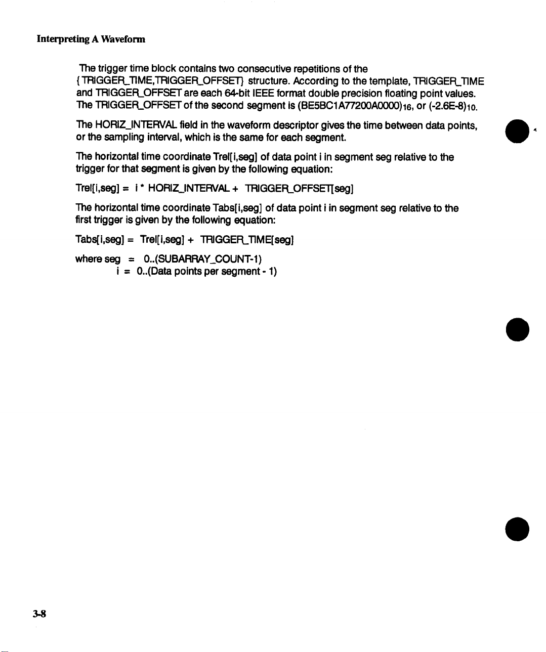
The trigger time block contains two consecutive repetitions of the
{ TRIGGER_TIME,TRIGGER_OFFSET} structure. According to the template, TRIGGER_TIME
and TRIGGER_OFFSET are each 64-bit IEEE format double precision floating point values.
The TRIGGER_OFFSET of the second segment is (BE5BC1A77200A0000)16, or (-2.6E-8)1o.
The HORIZ_INTERVAL field in the waveform descriptor gives the time between data points,
or the sampling interval, which is the same for each segment.
The horizontal time coordinate Trel[i,seg] of data point i in segment seg relative to the
trigger for that segment is given by the following equation:
Trel[i,seg] = i* HORIZ._INTERVAL+ TRIGGER_OFFSET[seg]
The horizontal time coordinate Tabs[i,seg] of data point i in segment seg relative to the
first trigger is given by the following equation:
Tabs[i,seg] = Trel[i,seg] + TRIGGER_TIME[seg]
where seg = 0..(SUBARRAY_COUNT-1)
i = 0..(Data points per segment - 1)
3-8
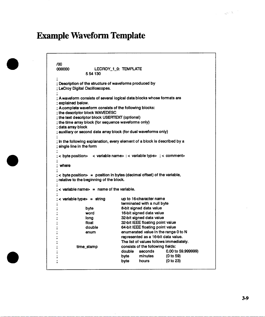
Example Waveform Template
/00
000000 LECROY_I_0: TEMPLATE
; Descdptlon of the structure of waveforms produced by
; LeCroy Digital Oscilloscopes.
; A waveform consists of several logical data blocks whose formats are
; explained below.
; A complete waveform consists of the following blocks:
; the descriptor block WAVEDESC
; the text descdptor block USE~ (optional)
; the time array block (for sequence wavetorms only)
; data array block
; auxiliary or second data array block (for dual waveforms only)
; In the following explanation, every element of a block is described by a
; single line in the form
; < byte position> < variable name> : < vadable type> ; < comment>
; where
; < byte position> = position in bytes (decimal offset) of the variable,
; relative to the beginning of the block.
564 130
; < vadabla name> = name of the vadable.
;< vadabletype> = stdng
byte
word
long
float
double
enum
time_stamp
up to 16-character name
terminated with a null byte
8-bit signed data value
16-bit signed data value
32Jolt signed data value
32-bit IEEE floating point value
64Jolt IEEE floating point value
enumerated value in the range 0 to N
represented as a 16-bit data value.
The list of values follows immediately.
consists of the following fields:
double seconds 0.00 to 59.999999)
byte minutes (0 to 59)
byte hours (0 to 23)
3-9

Example Waveform Template
byte days
byte months
word year
1 to 31)
(1 to 12)
(0 to 16000)
word unused
(There are 16 bytes in a time field.)
data
byte or word, as specified by the COMM_TYPE
vadable in the WAVEDESC block
text
unit_definition
arbitrary length text stdng (maximum 400)
48 character null-terminated ASCII stdng
for the unit name.
WAVEDESC: BLOCK
; Explanation of the wave descriptor block WAVEDESC ;
< 0> DESCRIPTOR_NAME: stdng ; the first 8 chars are always WAVEDESC
< 16>
< 32>
TEMPLATE_NAME: string
COMM_’I’YPE: enum
_0 byte
_1 word
endenum
< 34>
COMM_ORDER: enum
_0 HIRRST
_1 LORRST
endenum
3-10
t
; The following variables specify the block lengths of all blocks of which
; the entire waveform (as it is currently being read) is composed.
; If a block length is zero, the block Is (currently) not present.
;BLOCKS :
p
< 36> WAVE_DESCRIPTOR: long
< 40> USER_TEXT: long
I
; length In bytes of block WAVEDESC
; length in bytes of block USERTEXT
;ARRAYS :
t
< 44> TRIGTIME_ARRAY:Iong
e
< 48>
i
WAVE_ARRAY_I: long
< 52> WAVE ARRAY_2: long
; length In bytes of TRIGTIME array
; length in bytes of 1st data array
; length in bytes of 2nd data array
; The following variables Identify the instrument
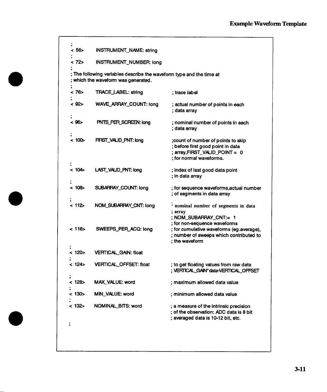
< 56> INSTRUMENT_NAME: string
< 72> INSTRUMENT_NUMBER: long
; The following variables descdbe the waveform type and the time at
; which the waveform was generated.
Example Waveform Template
< 76> TRACE_LABEL: string
< 92> WAVE_ARRAY_COUNT: long
< 96> PN1S_PER_SCREBq: long
< 100> RRST_V,N.ID_PNT: long
< 104> LAST_VALID_PNT: long
< 108>
< 112>
< 116> SWEEPS_PER_ACQ: long
< 120> VERTICAL_GAIN: float
< 124> VERTICAL_OFFSET: float
SUB~Y_COUNT: long
NOM_SUB.N:P, AY_CNT: long
; trace label
; actual number of points in each
; data array
; nominal number of points in each
; data array
;count of number of points to skip
; before first good point in data
; array,FIRST_VALID_POINT = 0
; for normal waveforms.
; index of last good data point
; in data array
; for sequence waveforms,actual number
; of segments in data array
; nominal number of segments in data
; array
; NOM_SUBARRAY_CNT:= 1
; for non-sequence waveforms
; for cumulative waveforms (eg.average),
; number of sweeps which contributed to
; the waveform
; to get floating values from raw data
; VE RT~AL_GAIN * data-VERTICAL_O FFS ET
< 128> MAX_VALUE: word
< 130>
< 132> NOMINAL_BITS: word
MIN_VALUE: word
; maximum allowed data value
; minimum allowed data value
; a measure of the intrinsic precision
; of the observation: ADC data is 8 bit
; averaged data is 10-12 bit, etc.
3-11
Example Waveform Template
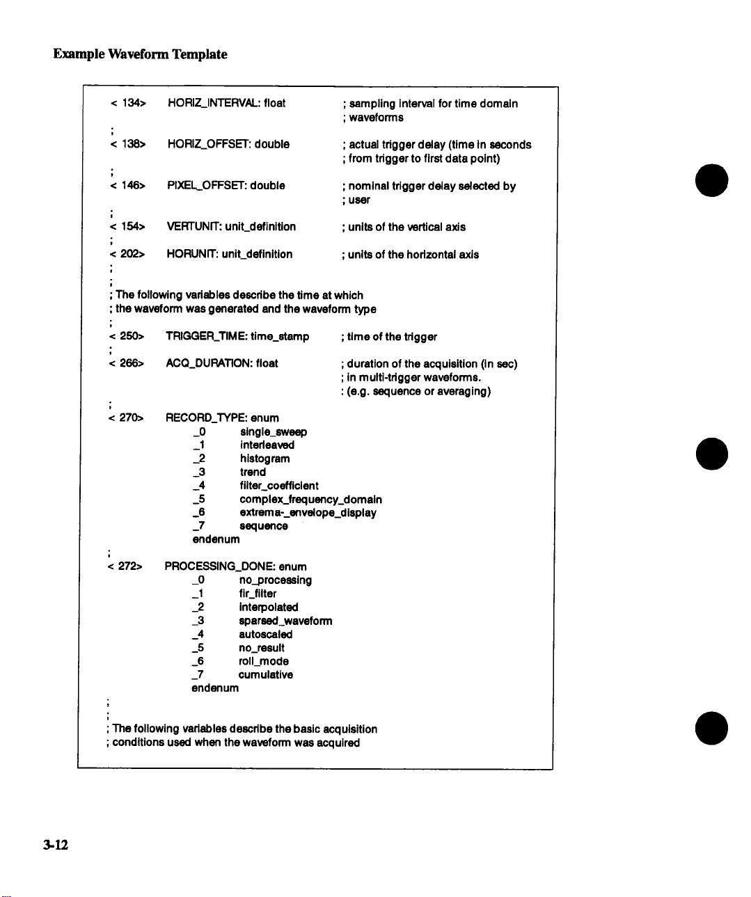
< 134> HORIZ_INTERVAL: float
< 138>
< 146> PIXEL_OFFSET: double
< 154>
< 202>
; The following variables descdbe the time at which
; the waveform was generated end the waveform type
< 250>
< 266>
< 270>
HORIZ_OFFSET: double
VERTUNIT: uniLdefinltlon
HORUNIT: uniLdeflnltlon
TRIGGER_TIME: time_stamp
ACQ_DURATION: float
RECORD_TYPE: enum
_0
_1 interleaved
_2 histogram
3
_4 filter_coefficient
_5 complex_frequency_domain
_6
7 sequence
endenum
single_sweep
trend
extrem a--envelope_display
; sampling interval for time domain
; wavoforms
; actual trigger delay (time In seconds
; from trigger to first data point)
; nominal trigger delay selected by
; user
; units of the vertical axis
; units of the horizontal axis
; time of the trigger
; duration of the acquisition (in sac)
;in multi-trigger waveforms.
: (e.g. sequence or averaging)
3-12
< 272>
; The following variables descdbe the basic acquisition
; conditions used when the waveform was acquired
PROCESSING_DONE: enum
_0 no_processing
_1 fir_filter
_2 Interpolated
-3 sparsed_wavaform
_4 autoscaled
_5 no_result
_6 roll_mode
_7 cumulative
endenum
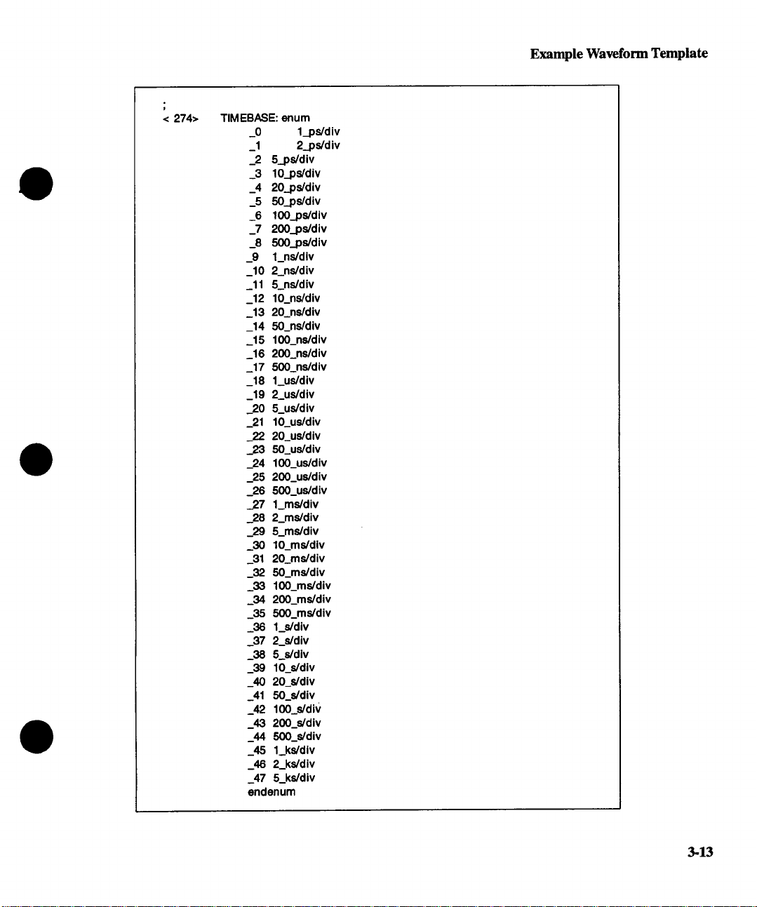
Example Waveform Template
< 274> TIMEBASE: enum
_0
_1
_2
_3
_4 20_ps/div
_5
_6 lO0_ps/div
_7 200_ps/div
_8
_9 l_ns/dlv
_10 2_ns/div
_11 5_ns/div
_12
_13
_14
_15 lO0_ns/div
_16 200_ns/div
_17
_18 l_us/div
_19 2_us/div
_20 5_us/div
_21 lO_us/div
_22 20_us/div
_23 50_us/div
_24 lO0_us/div
_25 200_us/div
_26 500_us/div
27 l_ms/div
_28 2_ms/div
_29 5_ms/div
30 lO_ms/dlv
_31 20_ms/div
_32 50_ms/div
_33 lO0_ms/div
_34 200_ms/div
_35 500_ms/div
_36 l_s/div
_37 2_s/div
_38 5_s/div
_39 lO_s/div
_40 20_s/div
_41 50_s/div
_42 lO0_s/div
_43 200_s/div
_44 500_s/div
_45 l.._k,Vdlv
_46 2_ks/div
_47 5_ks/div
endenum
l_ps/div
2._ps/div
5_ps/div
lO_ps/div
50_ps/div
500_ps/div
lO_ns/div
20_ns/div
50_ns/div
500_ns/div
3-13

Example Waveform Template
< 276>
< 278>
< 282>
VERT_COUPLING: enum
_0 DC_50_Ohms
_1 ground
._2 DC_IMOhm
_3 ground
_4 AC,_IMOhm
endenum
PROBE_ATT: float
FIXED_VERT_GAIN: enum
_0 l_uV/div
_1 2_uV/dlv
_2 5_uV/div
_3 10_uV/div
_4 20_uV/dlv
_5 50_uV/dlv
_6 100_uV/div
_7 200_uV/div
_8 500_uV/dlv
_9 l_mV/dlv
_10 2_mV/div
_11 5_mV/div
10_mV/div
_12
_13 20_mV/dlv
_14 50_mV/div
_15 100_mV/dlv
_16 200_mV/div
_17 500 mV/dlv
_18 l_V/div
_19 2_V/div
_20 5_V/dlv
_21 lO_V/div
_22
20_V/div
_23 50_V/dlv
_24 f 00_V/div
_25 200_V/dlv
500 V/div
_26
_27 1 kV/div
endenum
3-14
< 284>
< 286>
< 290>
< 294>
BANDWIDTH_LIMIT: enum
_0 off
_1 on,-60_MHz
endenum
VERTICAL_VERNIER: float
ACQ VERT_OFFSET: float
WAVE_SRC_PLUGIN: enum
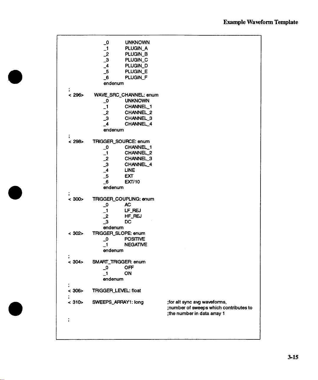
I
< 296>
i
< 298>
i
< 300>
< 302>
w
< 304>
_0 UNKNOWN
_1 PLUGIN_A
_2 PLUGIN_B
_3
PLUGIN_C
_4 PLUGIN_D
_5 PLUGIN_E
_6 PLUGIN_F
endenum
WAVE_SRC_CHANNEL: enum
_0
UNKNOWN
_1 CHANNEL_I
_2 CHANNEL_2
_3
CHANNEL_3
_4 CHANNEL_4
endenum
TRIGGER_SOURCE: enum
_0 CHANNEL_I
_1 CHANNEL_2
_2 CHANNEL_3
_3 CHANNEL_4
_4
_5
LINE
EXT
_6 EXT/10
endenum
TRIGGER_COUPLING: (mum
_0
AC
_1 LF_REJ
_2 HF_REJ
_3
DC
endenum
TRIGGER_SLOPE: enum
o
PosmvE
_1 NEGATIVE
endenum
SMART_TRIGGER: enum
_0 OFF
_1 ON
endenum
Example Waveform Template
< 306>
< 310>
TRIGGER_LEVEL: float
SWEEPS_ARRAY1: long
;for alt sync avg waveforms,
;number of sweeps which contributes to
;the number in data array 1
3-15

Example Waveform Template
< 314> SWEEPS_ARRAY2: long
;for alt sync avg waveforms,
;number of sweeps which contributed to
;the waveform In data array 1
J
/00 ENDBLOCK
t
J
USERTEXT: BLOCK
; Explanation of the descriptor block USERTEXT at most 400 bytes long¯
t
< O> DESCRIPTOR_NAME: stdng; the first 8 chars are always USERTEXT
< 16> TEXT:text
; this Is simply a list of ASCII
: characters
/00
ENDBLOCK
;=
t
TRIGTIME: ARRAY
t
; Explanation of the trigger time array (present for sequence waveforms only)
0> TRIGGER_TIME: double
; time In seconds from first trigger
; to this one
3-16
8> TRIGGER_OFFSET: double
/00 ENDARRAY
t-
WAVE_ARRAY_ 1: ARRAY
< 0> MEASUREMENT: data
;/00 ENDARRAY
; actual trigger delay time in
: seconds from this tdgger to
: first data point
; the actual format of a data Is
: given in the WAVEDESC descriptor
; by variable COMM_’I’YPE
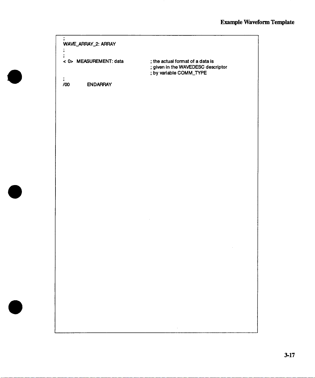
WAVE_ARRAY_2: ARRAY
Example Waveform Template
< O> MEASUREMENT: data
/00 ENDARRAY
; the actual format of a data is
; given in the WAVEDESC descriptor
; by variable COMM_TYPE
3-17

Section 4: Status Messages
This section describes the 7200A’s instrument status and event reporting functions. Although
the mechanisms for requesting service differ for GPIB and RS-232-C, status and event report-
ing is identical.
GPIB Service Request
When the 7200A reports a change in its condition, it can asynchronously request service from
the GPIB controller (e.g., the 7200A can request service when processing completes). The
7200A requests service by asserting the GPIB Service Request (SRQ) management line.
Once it has been enabled by setting the appropriate mask bits, the SRQ interrupts the control-
ler.
To identify the source of the SRQ, the controller serial polls the devices attached to the GPIB.
It reads the main Status Byte register (STB) of each device polled. To read the S’rB, the con-
troller addresses a device to talk and sends it a Serial Poll Enable bus command. In return,
the device sends its STB. The device whose S’rB has an asserted RQS bit (seventh bit) generated the SRQ.
Once the controller determines that the 7200A generated the SRQ, it will reset the SRQ line.
The 7200A will then reset its RQS bit.
RS-232-C Service Request
The RS-232-C interface does not have a line by which the 7200A can asynchronously request
service from the computer. Therefore, it must query (poll) the 7200A to read the STB register.
The computer issues the status command, *S’I’B? to query the 7200A for its STB register. The
seventh bit of the STB register (RQS bit for GPIB serial polling, MSS or Master Summary
Status bit for S’I’B) indicates that the 7200A requests service.
Status Byte Operation
The 720(0 continually updates its status to report the latest events, conditions, and settings.
Changes are summarized by designated bits in the Status Byte register (STB). The seventh
bit, RQS, is asserted whenever any other bits in the STB are reported as set and their corresponding mask bits are enabled. Also, whenever the RQS bit is set, the GPIB bus SRQ line is
automatically asserted.
Typically, the controller identifies the device requesting service. It reads the other bits in the
STB register and the associated status data structure to determine the cause of, and the conditions relating to the service request. For example, whenever the sixth bit (ESB) of the STB
4-1

Status Byte
register is set, an error or synchronization event has occurred. The controller then examines
the Event Status Register, a secondary status register within the status data structure, to ob-
tain details relating to that event.
Status Data Structures
In general, an asserted STB bit reflects, or summarizes, a change in a corresponding status
register. It can have an encoded number which indicates a specific event or condition. Alter-
nately, it can have each of its bits report, or summarize, a change in a third status register,
and so on.
Two types of status structures are the Register (individual bits) and the Queue (encoded number) models:
Register Model The Register Model requires that individual bits identify a specific
7200A condition or event.
Altemately, each bit could act as a summary bit for an associated
status register. Using bits in one status register to indicate
changes in other registers allows for a layered status description.
This layering of detail enables the controller to limit the amount of
information it receives. (Note: unless =Register Model" is specifically referenced, the term =register" refers to any byte(s) used
report a status condition or event.)
Queue Model
The following example illustrates the 7200A’s flexible status reporting capability. Each level
queried yields more details about the error. Query to the required extent to prevent extraneous information from traversing the GPIB.
4-2
The Queue Model is a single register which contains an encoded
number. For example, this number may be an error code which
corresponds to an error condition.
The 7200A’s queue can hold one error code. When read, the
queue will report the most recent error code, and then will clear it.
When the queue is cleared (empty), the corresponding bit in the
Register Model will be cleared. Conversely, when the queue contains an error code, the corresponding bit in the Register Model
will be set.
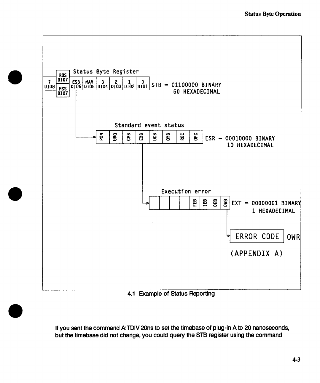
Status Byte Register
RQS
DI07 E:
MSS O!
DI07
Status Byte Operation
= 01100000 BINARY
60 HEXADECIMAL
Standard
event status
Execution error
4.1 Example of Status Reporting
ESR = 00010000 BINARY
10 HEXADECIMAL
w w 3
~
0
EXT = 00000001BINAR~
1 HEXADECIMAL
ERROR CODE OWR
(APPENDIX A)
If you sent the command A:’I’DIV 20ns to set the timebase of plug-in A to 20 nanoseconds,
but the timebase did not change, you could query the STB register using the command
4-3

Status Byte
* STB?. The 7200A would return the hexadecimal number 60 (see Figure 4.3), indicating that
the Event Status Register (ESR) changed.
Query another level deeper using * ESR?. The 7200A would return the hexadecimal number
10 for the value of the Event Status Register (ESR). This value means the Execution Error bit
was set. For more detail send EXR? to read the Execution Error Register. The response of 1
indicates that the Operator Warning bit is set.
Progressing one more step, send OWR? to query the Operator Warning Register. Since this
"register" is a queue, the 7200A sends back an error code. Referencing this byte in Appendix
A would reveal that a "data out of bounds" error occurred, since plug-in A’s timebase cannot
go below 50 nanoseconds.
Event Recording
IEEE-488.2 allows two ways to record an event:
Condition Registers Condition Registers are updated continually and are not cleared
when read. The 7200A has no condition registers.
Event Registers Event Registers capture changes in conditions. They are not
cleared until they are read, even if the condition which caused
the event no longer exists. Each bit in an Event Register either
summarizes a Condition Register, or reports a condition or event
in the 7200A.
4-4
NOTE" The *CLS command is provided to clear all Event
Registers without reading them firsL (The output queue
(and its MAVsummary bit) is treated as a Condition Register. It is not cleared by the *CLS command.)
NOTE" Only changes in bits can propagate to the main
status register. Therefore, the *CLS command should
be used before monitoring any register. Otherwise, if the
bit was previously set, setting it again will have no effect
on the main status byte.

Status Byte Operation
Event Enable Registers
Event enable registers also permit the controller to limit the amount of status information it receives. Every Register Model status register has an associated event enable register. By ma-
nipulating the associated event enable register, the controller can selectively enable or
suppress (mask) the reporting of specific instrument events. Each bit in an event enable regis-
ter is =AND’ed" with its corresponding bit in the status register. For example, if the controller
sets a bit in the Event Enable register, the corresponding status event can be reported. If it is
cleared, the event is masked and its reporting is disabled. In order for a service request to be
sent for an event, the corresponding bit in the event enable register, as well as all the bits
above it, must be set in order to propagate the bit up to the main status byte. For example, if
bit 0 in the * STB register gets set because a trigger got done and its corresponding event enable bit (bit 0) was set in the * SRE register, then the MSS bit will be set. If bit 0 was previously 0, then because it changed to a 1, the RQS bit (bit 6) will be set in the serial poll
register (along with bit 0) and the 7200A will generate an SRQ interrupt to the host computer.
If the computer performs a serial poll, the 7200A will reset bit 6 after sending its serial poll register to the host computer. However, the *S’FB register remains unaffected by this and willl
still contain decimal 65 (bits 0 and 6 set). Unless the INR register is cleared by reading it
sending * CLS, future trigger completions will not generate an SRQ because the previous
state was latched into the INR event register.
If a condition exists such that a bit is set in the *STB register but its corresponding bit in the
¯ SRE event enable register was not set, then the MSS bit and RQS bit will be 0 and no SRQ is
generated. However, performing a serial poll will show the bit to be set in the serial poll regis-
ter. If the event enable bit in the * SRE register then gets set, the unmasked bit set in the
¯ STB register will then set the MSS bit and the RQS bit and generate a service request (SRQ)
to the host computer.
In Figure 4.2, when the OWFI queue has an error code, the OWR bit is set in the EXR status
register.
The OWR bit has a corresponding bit set in the EXR event enable register. Since it is set, the
event is reported to the * ESR register. However, this event is not reported to the * STB status
register because the corresponding bit in the * ESR event enable register is cleared. Since all
other bits are cleared in the * ESR register, the ESB bit in the *STB register is also cleared.
Since no bits are set in the *STB, the MSS bit in the *STB is also cleared which causes the
RQS bit in the serial poll register to be 0 and no SRQ is generated by the 7200A.
When the 7200A is powered on, all masks are cleared; that is, all status event reporting is disabled.
4-5

Status Byte
o
o
o
o
~1
.arO
0
0
I [ *SRE
read by *STB
STATUS BYTE
read by sedal poll
OPERATOR WARNINGS
OWR ERROR CODE [
Queue
Not Empty
I
Standard Event Status Enable
0
IIIIIIIII’EsE
0
0
0
0
0
!!lll
0
o
I
IIII
TTT
I Ill I’ESR
Standard Event Status
Figure 4.2 Event Enable
Execution Error
IJllllll
JJJ
& & &
J Jllol 1,1,1,1
Execution Error Enable
’EXR
*EXE
4.6
Naming Convention
Naming Convention
The status registers follow a basic form which can be expressed as =xxR" (i.e., ESR, INR,
DPR, ...). Reference to the individual bits within the status register follow the form =xxB"
(i.e., ESB, INB, DPB .... ). Reference to the mask used to enable or disable certain bits within
each register follow the form =xxE" (i.e., ESE, INE, DPE .... ). The enable register may be set
pass or block the occurrence of certain events using the general form =xxE n" where n is the
value to set the enable register. For example, ESE 128 enables the PON bit in the ESR and
blocks the other bits. Only registers and masks may be queried according to the general
form =xxR?’. ’ and =xxE?". The following table summarizes these general forms:
xxB
xxR = Status xx Register
xxE = Status xx Enable mask
xxx? = Status xxx Query
xxE n = Set Status Enable mask xxE to value n
All the status bytes in the 7200A conform to either the register model or the queue model as
required by IEEE-488.2. If an event occurs which causes a bit in a register model to change
(either from a 0 to 1 or a 1 to 0), that change will be propagated to any overlaying registers,
provided the enable mask is set to pass that change. For example, the bits within the ESR
register are summarized by the ESB bit in the main status byte register (STB). If a bit in the
ESR register changes and the ESE mask is set to pass that change, then the ESB bit in the
main status register will be set or reset to reflect the change in the ESR.
If an event occurs which causes a byte to accumulate in a queue model, then the change will
propagate to any overlaying registers. For example, the CMR is summarized by the CMB bit
in the ESFL If a byte is placed in the CMR queue, the CMB bit will be set to indicate that the
queue is not empty. If the ESE mask is set to pass the change in the CMR, then the ESB bit in
the main status register will be set.
IEEE-488.2 defines certain =Common Commands", some of which are required for compliance to the standard. All IEEE-488.2 Common Commands are three letter names preceded
by an asterisk(*). For example, * RST, * IDN? ....
= Status xx Bit
4-7
Status Byte
STB Standard Definition
This section describes the function and structure of all the status registers. The main Status
Byte register (STB) reflects instrument status at the time it is read. This register is usually read
when the system controller polls the 7200A. Bits in the STB summarize all the other status registers. This summary occurs by "OFring" all the reported bits in a summarized register. If the
result is TRUE, the summary bit is set. Those registers which the STB summarizes can, in
turn, summarize other registers in the same way.
The STB is read with the command * STB?. Its event enable register, or mask, is set with
¯ SRE n. The mask is read with *SRE?. (Note: n is the sum of the decimal bit weights of all bits
that are true.)
The * STB? query does not alter any bits in the status byte. Only the * CLS command can
clear the status byte, except for the MAV Message Available bit which depends on the state
of the Output queue. STB is shown in Figure 4.3.
4-8
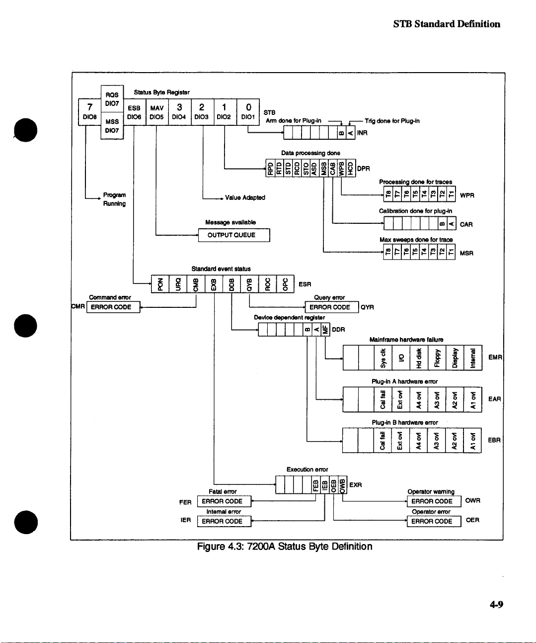
7
[:)108
I
Status Byte Reglster
RQS
DIG7
,.l,,v o:I01
DI06 DI05 DI04 DI03 DI01
MSS
D107
STB Standard Definition
STB
Ann done for Plug-in -~ ~ Tdg done for Plug-ln
,I I I J [ I i=kl,..
¯ Program
Running
--.~ OUTPUT QUEUE I
Commend error
3MR [ ERFIOR CODE ]. I
. VAII|A At~nt~t
Message available
Standard event status
~ ol m
Data p~ssln!
Query error
Device dependent register
II]II I r~l~l
°°~
I
___~ I
--] I I~1~1~1,~1~1~1
done
Processing done for traces
.~-~:~-~-~-~ WPR
Calibmtlon done for plug-ln
I
Max sweeps done for trace
"~- ~ ~- ~-- ~- ~-- ~-- ~ MSR
Mainframe hardware fallum
=~ >, ~ -
Rug-in A hardware error
I = I’o I -o I -o I -o I -o I
I INI~I~I~I~I~I
Plug-in B hardware error
J I I :, I’o I -o I ~ I -o I -o I
EMR
EAR
EBR
Execution error
Fatal error
Internal error Operator error
t I I I I~lm_.~O[ooIEXR
Operatorwamlng
Figure 4.3: 7200A Status Byte Definition
4-9
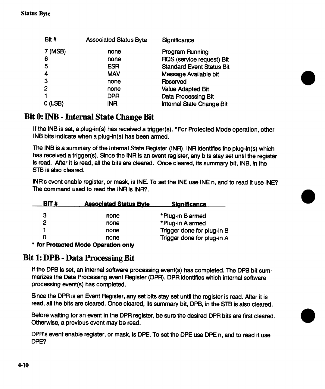
Status Byte
Bit # Associated Status Byte
7 (MSB)
6 none RQS (service request) Bit
5 ESR
4
3
2 none Value Adapted Bit
1
0 (LSB) INn Internal State Change Bit
Bit 0:
INB - Internal State Change Bit
If the INB is set, a plug-in(s) has received a trigger(s). * For Protected Mode operation, other
INB bits indicate when a plug-in(s) has bean armed.
The INB is a summary of the Internal State Register (INn). INn identifies the plug-in(s) which
has received a trigger(s). Since the INn is an event register, any bits stay set until the register
is read. After it is read, all the bits are cleared. Once cleared, its summary bit, INB, in the
STB is also cleared.
INn’s event enable register, or mask, is INE. To set the INE use INE n, and to read it use INE?
The command used to read the INn is INFI?.
BIT #
Associated Status Byte
none Program Running
MAV Message Available bit
none Reserved
DPR
Significance
Standard Event Status Bit
Data Processing Bit
Sl_onlflcance
3
2 none
1
0
for Protected Mode Operation only
*
none
none
none
* Plug-in B armed
*Plug-in A armed
Trigger done for plug-in B
Trigger done for plug-in A
Bit 1: DPB - Data Processing Bit
If the DPB is set, an internal software processing event(s) has completed. The DPB bit sum-
marizes the Data Processing event Register (DPR). DPR identifies which internal software
processing event(s) has completed.
Since the DPR is an Event Register, any set bits stay set until the register is read. After it is
read, all the bits are cleared. Once cleared, its summary bit, DPB, in the STB is also cleared.
Before waiting for an event in the DPR register, be sure the desired DPR bits are first cleared.
Otherwise, a previous event may be read.
DPR’s event enable register, or mask, is DPE. To set the DPE use DPE n, and to read it use
DPE?
4-10
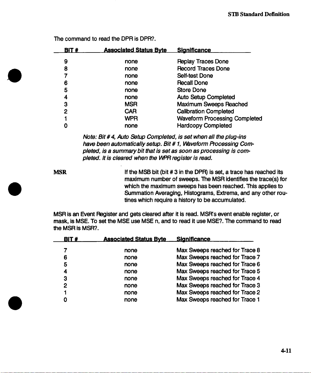
The command to read the DPR is DPR?.
STB Standard Definition
BIT #
9 none
8 none
7 none
6
5
4 none
3 MSR
2
1 WPR
0
Note: Bit # 4, Auto Setup Completed, is set when all the plug-ins
have been automatically setup. Bit # 1, Waveform Processing Com-
pleted, is a summary bit #1at is set as soon as processing is completed. It is cleared when the WPR register is read.
MSR If the MSB bit (bit # 3 in the DPR) is set, a trace has reached its
MSR is an Event Register and gets cleared after it is read. MSR’s event enable register, or
mask, is MSE. To set the MSE use MSE n, and to read it use MSE?. The command to read
the MSR is MSR?.
Associated Status Byte
none
none
CAR
none
maximum number of sweeps. The MSR identifies the trace(s) for
which the maximum sweeps has been reached. This applies to
Summation Averaging, Histograms, Extrema, and any other routines which require a history to be accumulated.
Sianlficance
Replay Traces Done
Record Traces Done
Self-test Done
Recall Done
Store Done
Auto Setup Completed
Maximum Sweeps Reached
Calibration Completed
Waveform Processing Completed
Hardcopy Completed
BIT # Associated Status Byte Significance
7 none Max Sweeps reached for Trace 8
6
5
4
3 none
2 none Max Sweeps reached for Trace 3
1
0 none
none Max Sweeps reached for Trace 7
none Max Sweeps reached for Trace 6
none Max Sweeps reached for Trace 5
Max Sweeps reached for Trace 4
none Max Sweeps reached for Trace 2
Max Sweeps reached for Trace 1
4-11
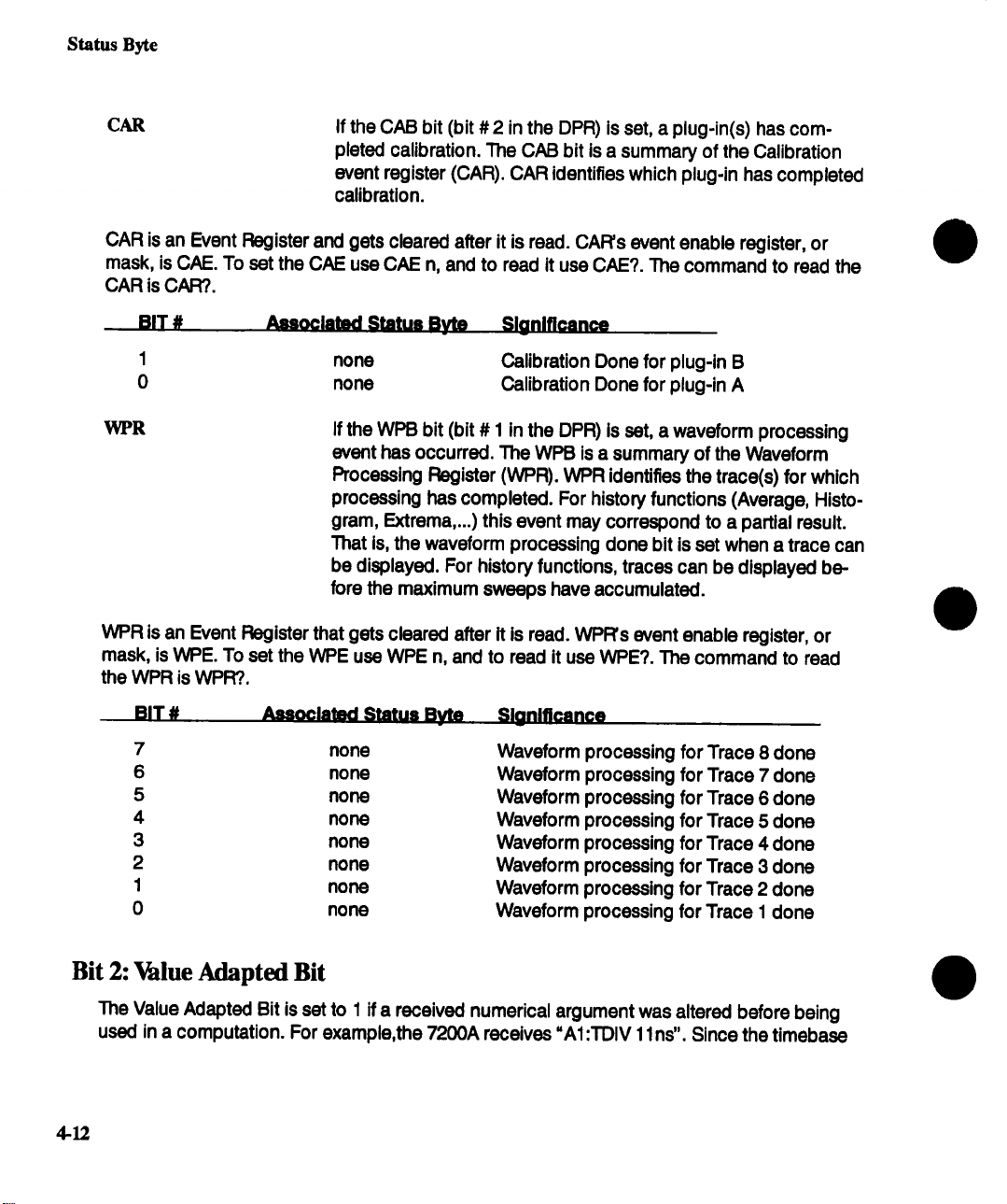
Status Byte
CAR
CAR is an Event Register and gets cleared after it is read. CAR’s event enable register, or
mask, is CAE. To set the CAE use CAE n, and to read it use CAE?. The command to read the
CAR is CAR?.
BIT # .~oclatad Status Byte
I
0
WPR
WPR is an Event Register that gets cleared after it is read. WPR’s event enable register, or
mask, is WPE. To set the WPE use WPE n, and to read it use WPE?. The command to read
the WPR is WPR?.
If the CAB bit (bit # 2 in the DPR) is set, a plug-in(s) has
pleted calibration. The CAB bit is a summary of the Calibration
event register (CAR). CAR identifies which plug-in has completed
calibration.
Sl_anlflcan_,~_
none
none
If the WPB bit (bit # 1 in the DPR) is set, a waveform processing
event has occurred. The WPB is a summary of the Waveform
Processing Register (WPR). WPR identifies the trace(s) for which
processing has completed. For history functions (Average, Histogram, Extrema,...) this event may correspond to a partial result.
That is, the waveform processing done bit is set when a trace can
be displayed. For history functions, traces can be displayed before the maximum sweeps have accumulated.
Calibration Done for plug-in B
Calibration Done for plug-in A
BIT # Assoclatad Stat-~ Byte
7
6
5
4
3
2
1
0
no ne
none
none Waveform
none Waveform
none Waveform
none Waveform
none
none
Slonlflcance
Wavefo r m
Waveform
Waveform
Waveform
:~rocessing for Trace 8 done
3rocessing for Trace 7 done
3rocessing for Trace 6 done
3rocessing for Trace 5 done
3rocessing for Trace 4 done
3rocessing for Trace 3 done
~rocessing for Trace 2 done
3rocessing for Trace 1 done
Bit 2: Value Adapted Bit
The Value Adapted Bit is set to 1 if a received numerical argument was altered before being
used in a computation. For example,the 7200A receives "AI:TDIV 1 lns". Since the timebase
4.12

STB Standard Definition
can only be set in multiples of 1,2, and 5, the 11 ns would get rounded to 10ns. The Value
Adapted bit would be set to report that the received value was altered.
Bit 4: MAV- Message Available Bit
MAV is set if data is in the output queue. It informs the system controller that there is still data
to output. It is reset once the output queue is empty, indicating that the system controller has
read the data from the 7200A. This condition bit is not set or reset when the system controller
reads STB. Also, the *CLS command does not affect this bit.
Bit 5: ESB - Event Status Bit
If the ESB is set, an error(s) or user front panel request(s) has occurred. The ESB is a
mary of the Event Status Register (* ESR). IEEE-488.2 defines the * ESR to report error conditions common to most automatic test equipment. The 7200A uses most but not all of these
bits for synchronization and error reporting.
The * ESR identifies the type of error or whether a front panel request has occurred. Since the
¯ ESR is an Event Register, any set bits stay set until the register is read. After it is read, all the
bits are cleared. Once cleared, its summary bit (ESB) in the STB is also cleared.
¯ ESR’s event enable register, or mask, is * ESE. To set the * ESE use * ESE n, and to read it
use * ESE?. The command to read the * ESR is * ESR?..
The definition of the bits in the * ESR follow:
BIT #
7 none
6 none
5
4
3 DDR
2 QYR
1 none
0
URQ
Associated Status Byte
CMR
EXR
none
This event bit indicates that an off-to-on transition has occurred
in the 7200A’s power supply.
The User Request bit is set when the Remote Host port and Hardcopy ports are both set to GPIB and the front panel Hardcopy
button is pressed. In this case, if the Hardcopy were to start, the
7200A would enter Talk-Only mode and disrupt the connected
Remote Host. To prevent this, the User Request bit is set allowing
the Remote Host to detect the Hardcopy request and initiate it re-
Sionlflcance
Power On
User Request(Local Hardcopy Request)
Command Error (syntax,unknown, cmd,...)
Execution Error (invalid parameter,...)
Device Dependent Error (CAL error,...)
Query Error
Request Control
Operation Complete
4-13

Status Byte
motely after first setting up all connected devices. Refer to Section 1 for more information.
CMR
EXR
BIT #
If the CMB (Bit # 5 in the ESR) is set, a command parsing error
has occurred. The CMB bit summarizes the Command Parsing
Register(CMR). The CMR identifies the most recent command
parser error. The CMR is a 16-bit queue which contains a unique
encoded value. Refer to Appendix A: Command Errors, for a listing of possible command errors.
If the ~ (Bit # 4 in the ESR) is set, a command execution error(s) has occurred. The EXB bit summarizes the Command Exe-
cution register (EXR). The EXR identifies the category
command execution errors. Each of four bits in the EXR corresponds to a different category of error/warning condition. A bit is
set when its category of error occurs. A 16-bit queue for each
category contains the most recent code.
Status Byte
FER
IER
OER
OWR
Typical errors include:
prefix illegal
too many parameters
plug-in not present
data block error
data block descriptor error
data processing error
units do not match
Slaniflcance
Fatal Error
Internal Error
Operator Error
Operator Warning
4-]4
DDR
If the DDB (Bit # 3 in the ESR) is set, a device specific error(s)
has occurred. The DDB bit summarizes the Device Dependent
Register (DDR). The DDR specifies the origin of the failure (plugin(s) and/or mainframe). Each bit in the DDR is a summary mes-
sage bit for a status register corresponding to each plug-in and
for the mainframe. The DDR is an event register that gets cleared
when read.

STB Standard Definition
DDR’s event enable register, or mask, is DDE. To set the DDE use DDE n, and to read it use
DDE?. The command to read the DDR is DDR?.
BIT #
2 EBR Plug-in B error
1
0 EMR Mainframe error
ExRBits
The x in ExR represents M,and A and B for mainframe and plug-ins, respectively.
ExR’s event enable register, or mask, is ExE. To set the ExE use ExE n, and to read it use
ExE?. The command to read the ExR is ExR?.
Typical device specific errors include channel overloads, hardware failures, and self-test fail-
ures. This is an event register and gets cleared after it is read.
Bit assignments for ExR, for the plugin:
BIT # Associated Status Byte Slanlflcance
5
4
3
2
1 none
0
Associated Status Byte Si_onificance
EAR Plug-in A error
These bits indicate the type of device specific error. Each plug-in
and mainframe bit in the DDR summarizes an ExR register. The
system controller can read these registers to determine the type
of error which occurred in the plug-in or mainframe. The definition of the bits in the ExR for all the plug-ins are the same.
none Calibration Failed
none External overload
none Channel 4 overload
none Channel 3 overload
Channel 2 overload
none
Channel 1 overload
Bit assignments for EMP~
BIT #
7 none reserved
6
5
4
3 none
2
1
0 none
Associated Status Byte Si_oniflcance
none reserved
none System clock failure
none I/O failure
Hard disk failure
none
none
Floppy failure
Display failure
Internal comm. failure
4-15

Status Byte
QYR
RQC
OPC
If the QYB (Bit #2 of ESR) is set, a query error(s) has occurred.
The QYB bit summarizes the Query Error Register (QYR). QYR
identifies the most recent query error. The QYR is a 16-bit queue
which contains a unique encoded value. The value indicates
query errors. Typical errors include:
Query CHANNEL ALL when both channels are not equal.
Buffer deadlock: input and output buffers full.
Unterminated: controller reads before sending a complete
query message.
Interrupted: controller sends new command before reading
last query.
Query after indefinite response.
The Request Control bit in the ESR is never set because the
7200A does not have controller capability.
To conform to IEEE-488.2, the 7200A will set the OPC bit (Bit #
in the ESR) in response to an *OPC command. The query
* OPC? will return a
This bit is set upon completion of any operation. At any one time,
several operations can be performed and be in various states of
completion. To correctly determine which operation completed,
monitor the Internal State Register (INR) and the Data Processing
Register (DPR).
"1".
Bit 6: RQS - Request Service Bit
The RQS bit is a summary bit for the other bits in the STB byte. For GPIB, an SRQ interrupt is
generated when the RQS bit is set if the corresponding bit in the SRE mask is set. For
RS-232-C, the computer must poll the STB register and read the FIQS bit to determine the
most recent status.
Bit 7: Program Running Bit
This bit is set when an ICL Program (See Section 7) is executing and is reset when the ICL
Program has completed execution.
NOTE" When an ICL Program is running, remote commands are
locked out. Therefore, bit 7 of the main status byte should always be
checked (using a serial poll) before sending remote commands
ensure proper remote operation.
4.16

Mainframe Remote Comnmnds
Section 5: Mainframe Remote Commands
Acquisition Commands
"TRG .................... 5-179
*TST? .................... 5-180
AFWI_ACQUISmON ARM .......... 5-7
AUTOSETUP ASET ............ 5-9
REFERENCE_CLOCK RCLK ........ 5-131
STOP ....................
TIMEBASE._LOCK TBLK ..........
TRIG_ENABLE TREN ............ 5-150
TRIG_LOCK TRLK ............. 5-151
TRIG_MODE TI:~ID ............. 5-152
WAIT ..................... 5.156
ALL_STATUS? ALST? ............
AF~I_ACQUISmON AFWl .......... 5-7
AUTO_CAL ACAL .............. 5-8
AUTO_SETUP ASET ............ 5-9
AXIS_LABEL AX]L .............. 5-10
BUZZER BUZZ ............... 5.11
CAE .....................
Calibration and Test Commands
*CAL? .................... 5-168
*FIST ..................... 5-176
AUTO_CAL ACAL .............. 5-8
CAR .....................
CENT .................... 5-14
CENTER_MAX CMAX ............ 5-16
CLEAR_DISPLAY CLRD .......... 5-17
CLEAR_MEMORIES CLRM ......... 5-18
CMR ..................... 5-19
COLOR COLR ............... 5-20
COMM_FORMAT CFMF ..........
COMM_HEADER CHDR .......... 5-24
COMM_ORDER CORD ........... 5-25
COMM_RS232 CORS ........... 5-26
COMM_SCSI COSC ............ 5-28
Communication Commands
*WAI ..................... 5-181
CENT ....................
COMM_FORMAT CFMT ..........
COMM_HEADER CHDR .......... 5-24
COMM_ORDER CORD ........... 5-25
COMM_RS232 CORS ........... 5-26
5-137
5-143
5-6
5.12
5-13
5-22
5-14
5-22
COMM_SCSI COSC ............ 5-28
DATA_DEST DDST ............. 5.36
GPIB_ADDRESS GPAD ........... 5-66
LOCAL LOC ................. 5-84
LOCKOUT LLOK .............. 5-85
REM CTRL RCTL .............. 5-133
REMOTE REM ................ 5-132
SCSI_ID? SCID? ............... 5-135
TFIANSFER_RLE TRR ...........
COPY_RLE COPY .............
CURSOR LOCK CRLK ........... 5--30
Cursor Meaeursmant Commands
CURSORLOCK CRLK ........... 5-30
CURSOR_MEASURE CI:~IS ........ 5-31
CURSOR_SET CRST ............ 5-32
CURSOR_VALUE? CRVA? ......... 5-34
PARAMETER_ADD PAAD .......... 5-92
PARAMETER_AVG PAAV .......... 5-103
PARAMETER_CLR PACL .......... 5-104
PARAMETER_DEL PADL .......... 5-105
PARAMETER_VALUE? PAVA ........
PER_CURSOR_SET PECS ......... 5-108
PER_CURSOR_VALUE PECV ........ 5-110
XY_CURSOR_ORIGIN XYCO ........ 5-162
XY_CURSOR_SET XYCS .......... 5-163
XY_C URSOR_VALUE XYCV ........ 5-165
CURSOR_MEASURE CF~S ........ ,5-31
CURSOR_SET CRST ............ 5-32
CURSOR_VALUE? CRVA? ......... 5-34
DATA_DEST DDST ............. 5-36
DATE ..................... 5-37
DDE ..................... 5-38
DDR ..................... 5-39
DEFINE DEF ................. 5-40
DERNE_REPLAY DEFR ........... 5-48
DELETE_RLE DELF ............. 5-49
DIRECTORY_LIST DIR ........... 5-50
Display Commands
AXIS_LABEL AX]L .............. 5-10
BUZZER BUZZ ............... 5-11
COLOR COLR ................ 5-20
DISPLAY DISP ................ 5-51
5-148
5-29
5-106
5-1

Mainframe Remote Commands
Mainframe Remote Commands (continued)
DISPLAY_UPDATE DISU .......... 5-52
DOT_JOIN DTJN .............. 5-53
GRID_STYLE GRDS ............
HIST_ORIENT HISO ............
HOR_MAGNIFY HMAG ...........
HOR_POSITION HPOS ........... 5-77
INTENSITY INTS ..............
MULTI_ZOOM MZOM ...........
MULTI_ZOOM_SETUP MZSU .......
PERSIST PERS ............... 5-112
PERSIST_SETUP PESU .......... 5-113
RECALLPANELS RCPN .......... 5-127
SELECT SEL ................ 5-136
STORE_PANELS STPN ...........
TRACE TRA ................. 5-144
TRACE_ANOT TRAA ............
VERT_IVlAGNIFY VlVlAG ........... 5-154
VERT_POSITION VPOS ..........
XY_A,SSIG N XYAS .............
XY_DISPLAY XYDS ............. 5-167
DISPLAY DISP ............... 5-51
DISPLAY_UPDATE DISU ..........
DOT_JOIN DTJN ..............
DPE ..................... 5-54
DPR .....................
EAE, EBE ..................
EAR?, EBR? .................
EME ..................... 5-59
EMR ..................... 5-60
EXE .....................
EXR ..................... 5-62
FER? ....................
FIND_CTR_RANGE FCR ..........
FORMA’rr_FLOPPY FFLP .........
GPIB_ADDRESS GPAD ...........
GRID ..................... 5-67
GRID_STYLE GRDS ............ 5-68
Hardcopy Commands
HARDCOPY HCPY ............. 5-69
HARDCOPY_SETUP HCSU ........ 5-70
HARDCOPY_TRANS HCTR ......... 5-74
HARDCOPY HCPY .............
HARDCOPY_SETUP HCSU ........
5-68
5-75
5-76
5-83
5-88
5-89
5-139
5-145
5-155
5-161
5-52
5-53
5-55
5-57
5-58
5-61
5-63
5-64
5-65
5-66
5-69
5-70
HARDCOPY_TRANS HCTR ........
HIST_ORIENT HISO ............
Histogram Paramaters ........... 5-100
HOR_MAGNIFY HMAG ..........
HOR_POSmON ..............
Identification/Data Commands
*IDN? .................... 5-172
"OPT? ...................
DATE .................... 5-37
PRW ON STATE PWRO .......... 5-124
UPTIME UPTI ................ 5-153
IER? .....................
INE ..................... 5-79
INR? ....................
INSPECT? ................. 5-81
INTENSITY ................. 5-83
LOCAL ...................
LOCKOUT .................
MSE ....................
MSR ....................
MULTI_ZOOM MZOM ...........
MULTI_ZOOM_SETUP MZSU .......
OER? .................... 5-90
OWR? .................... 5-91
PARAMETER_ADD PAAD .........
PARAMETER_AVG PAAV ..........
PARAMETER CLR PACL ......... 5-104
PARAMETER_DEL PADL ..........
PARAMETER_VALUE? PAVA? .......
PER CURSOR_SET PECS .........
PER_CURSOR VALUE? PECV? ......
PERSIST PERS ............... 5-112
PERSIST_SETUP PESU .......... 5-113
PROG_ARG PRAR ............. 5-114
PROG_CLEAR PRCL ............
PROG_COMPILE PRCO ..........
PROG_LIST PRLI ..............
PROG_MODE PRMO ...........
PROG_RECALL PRRC ...........
PROG_SETUP PRSU ............
PROG_STORE PRST ............
5-74
5-75
5-76
5-77
5-175
5-78
5-80
5-84
5.85
5-86
587
588
589
5-92
5-103
5-105
5-106
5-108
5-110
5-115
5-116
5-117
5-118
5-119
5-120
5-122
5-2

Mainframe Remote Commands
Mainframe Remote Commands (continued)
Program Commands
*LRN? ....................
PROG_ARG PRAR .............
PROG_CLEAR PRCL ............
PROG_COM PILE PRCO ..........
PROG_LIST PFLI ..............
PROG_MODE PRMO ............
PROG_RECALL PRRC ........... 5-119
PROG_SETUP PRSU ............
PROG_STORE PRST ............
PROTECT_MODE PF~ID ($I Option only)
PRW_ON_STATE PWRO ($I Option only) 5-124
QYR? .................... 5-125
RECALL REC ................
RECALL_PANELS ROPN ..........
RECALL_SETUP RCST ...........
RECORD_TRACES RECT .........
REFERENCE_CLOCK RCLK ........
REM_CTRL RCTL ..............
REMOTE REM ...............
REPLAY_TRACES REPT ..........
SCSI_ID? SCID? ..............
SELECT SEL ................
Status Register Commands
*CLS ....................
* ESE ....................
*ESR? ....................
*OPC .................... 5-174
*SRE ....................
*STB? ....................
ALL_STATUS? ALS’T’? ...........
CAE .....................
CAR?. ....................
CMR? ....................
DDE ..................... 5-38
DDR? .................... 5-39
DPE .....................
DPR? ....................
EAE, EBE ..................
EAR?, EBR? .................
EME .....................
EMR? ....................
EXE .....................
5-173
5-114
5-115
5-116
5-117
5-118
5-120
5-122
5-123
5.126
5.127
5.128
5.130
5-131
5-133
5-132
5-134
5-135
5-136
5-169
5-170
5-171
5-177
5-178
5-6
5-12
5.13
5.19
5-54
5.55
5-57
5-58
5-59
5-60
5-61
EXR? .................... 5-62
FER? ..................... 5.-63
IER? .....................
INE ...................... 5-79
INR?. .....................
MSE .....................
MSR? ....................
OER? .................... 5-90
OWR? .................... 5-91
QYR? ....................
WPE .....................
WPR? .................... 5.160
STOP .................... 5-137
STORE STO .................
STORE_PANELS STPN ...........
STORE_SETUP STST ............
TEMPLATE? TMPL? ............ 5.142
TIMEBASE_LOCK TBLK .......... 5.143
Trace Equation Setup
CENTER_MAX CMAX ............ 5-16
CLEAR_DISPLAY CLRD ........... 5-17
DEFINE DEF .................
DEFINE_REPLAY DEFR ...........
RND_CTR_RANGE FCR ..........
TRACE_LABEL TRLB ............ 5-147
TRACE TRA .................
TRACE_ANAT TRAA ............. 5.145
TRACE_LABEL TRLB ............
TRANSFER_FILE TRR ........... 5-148
TRIG_ENABLE TREN ($1 Option only)... 5-150
TRIG_LOCK TRLK ..............
TRIG_MODE TFWlD .............
UPTIME UPTI ................
VERT MAGNIFY VMAG ...........
VERT_POSITION VPOS ........... 5-155
WAIT ..................... 5.156
Waveform Storage
CLEAR_MEMORIES CLI:~ .........
COPY_RLE COPY .............
DELETE_FILE DELF ............. 549
DIRECTORY_LIST DIR ........... 5-50
FOF~IAT_FLOPPY FFLP .......... 5-65
5-78
5-80
5-86
5-87
5-125
5.159
5-138
5-139
5.140
5-40
5-48
5-.64
5.144
5-147
5-151
5.152
5.153
5-154
5-18
5.29
5-3

Mainframe Remote Commands
Mainframe Remote Commands
PROTECT_MODE PFWlD ..........
RECALL REC ................
RECALL_SETUP RCST ........... 5-128
RECORD_TRACES RECT ......... 5-130
REPLAY_TRACES PEP1" .......... 5-134
STORE STO ................
STORE_SETUP STST ........... 5-140
Waveform Tran=fer Commands
INSPECT INSP ............... 5-81
TEMPLATE TMPL? .............
WAVEFOF~I WF ..............
WAVEFOFWI? WF? ............. 5-158
WAVEFO FIM WF ..............
WAVEFOF~? WF? .............
WPE .....................
WPR? .................... 5-160
XY ASSIGN XYAS ............. 5-161
XY_CURSOR_ORIGIN XYCO ....... 5-162
XY_CURSOR_SET XYCS .......... 5-163
XY_C URSOFLVALUE? XYCV? ...... 5-165
XY_DISPLAY XYDS .............
5-123
5-126
5-138
5-142
5-157
5-157
5-158
5-159
5-167
(continued)

Mainframe Remote Commands
Organization
Each command description begins a new page. A command’s name (header) is printed
long and short form near the top of the page. Although the long form is used in the descrip-
tion, the short form can be used instead. Below the header are up to eight sections which de-
scribe it:
Purpose: explains a command’s use
Command: contains a command’s syntax
Query: contains the query syntax
Response: contains the syntax of the response to a query
Argument:
Example: includes the command being used
Note: reports additional considerations
See Also: cites other relevant commands
defines a choice(s)
Command Execution
Execution of program messages depends on the instrument status. As a rule, commands and
queries can be executed in either Local or Remote mode.
Before attempting to execute a command or query, the parser scans it to verify its correctness and that sufficient information is given to perform a requested action.
5-5

Mainframe Remote Commands
ALL_STATUS?
Purpose:
Query.
Response:
Argument:
Examples:
See Also:
The query commands for each of these status registers.
ALST?
Reads the contents of all status registers. After event registers are read,
they are cleared. For an interpretation of each register’s contents, refer to
the appropriate status register description.
The ALST? query is useful for a complete overview of the instrument’s state.
ALL_STATUS?
ALL_STATUS register,value,register,value ....
register Indicates the register mnemonic.
value Indicates register contents.
ALL_STATUS? Read the contents of all status registers.
ALL_STATUS * S’rB,0,* ESR,0,CMR,0,EXR,0,FER,0,1ER,0,OER,0,
OWR,0,DDR, O,EBR, O, EAR,0, EM R,0,QYR,O,
DPR,0,MSR,0,CAR,0,WPR,0,1NR,0 < end>
5-6
Mainframe Remote Commands
ARM_ACQUISITION
Purpose:
Command:
Note:
See Also:
Enables the signal acquisition process by changing the acquisition state
from TRIGGERED to READY.
ARM_ACQUISITION
This command works identically as the *TRG command.
*TI:~
ARM
5-7
Mainframe Remote Commands
AUTO_CAI,
Purpose:
Command:
Query:.
Response:
Argument:
Examples:
Note:
ACAIJ
To enable or disable automatic calibration of 7200A plugins.
AUTO_CAL state
AUTO CAL?
AUTO_CAL state
state ON
OFF
ACAL ON
ACAL?
ACAL ON
Automatic caUbration is always enabled when the 7200A is powered on or
reset.
I/Vhen controlling the 7200A from remote, it is recommended that automat-
ic calibrations are disabled, since they will occur asynchronously and can
take several seconds per plug-in to complete. However, if you do disable
it, periodic calibrations should be performed via the *CAL ? command.
Causes the 7200A to periodically perform an automatic
recalibration of the plugins.
Disables automatic recalibration of plugins.
enables automatic calibration.
Queries whether automatic calibration is enabled
or disabled.
Reports than automatic calibration is enabled.
See Also:
5-8
* CAL?
Mainframe Remote Commands
AUTO_SETUP
Purpose:
Command:
Notes:
Sets up acquisition parameters automatically. The command attempts to
display the input signal(s) by adjusting the vertical, timebase, and trigger
parameters. If input signals are available and more than one channel is be-
ing displayed, the signals will be scaled vertically and the timebase will be
chosen to best display Channel 1. If only one input channel is turned on,
the timebase will be adjusted for that channel.
AUTO_SETUP
When locked timebase is selected, the Umebase controls will be set up
based on the leftmost plugin’s control settings.
ASET
5-9
Mainframe Remote Commands
AXIS_LABEL
Purpose:
Command:
Query:.
Response:
Arguments:
Example:
See Also:
AXIL ON
AXIL?
AXIL
SELECT
AXIL
This command enable/disables the display of the end point values for the
active trace on both the horizontal and vertical axes. If enabled, the values
are printed when the grid is either single or dual.
AXIS_LABEL state
AXIS_LABEL?
AXIS_LABEL state
state ON
OFF
OFF
displays the values corresponding to the active trace at
the end of each axis.
takes the values of the axes off the display.
tells the 7200A to display the axis values.
asks if the axis lables are on or off.
response indicates axis labels are not displayed.
5-10
Mainframe Remote Commands
BUZZER BUZZ
Purpose:
Command:
Briefly sounds the buzzer.
BUZZER
5-11
Mainframe Remote Commands
Purpose:
Command:
Query:.
Response:
Argument:
Examples:
Sets the Calibration Enable register (CAE). The CAE register determines
which events in the Calibration status Register (CAR) are reported. CAR
identifies which plug-in has completed calibration. Any reported CAR event
sets the CAB summary message bit (bit # 2) of the Data Processing Register (DPR) and propagates to the main Status Byte (STB).
CAE mask
CAE?
CAE mask
mask
CAE 3
CAE?
CAE 3
When expressed in binary, this number (between 0 and 63)
represents the bits of the CAR that can be reported:
Bit #
1
0
enables the events represented by the lower two bits of this
event register (i.e., calibration done for plug-ins A and B).
bit 1 (decimal 2), and bit 0 (decimal 1). Summing the decimal
values yields 3.
Read the contents of the CAE.
Response indicates the contents as 3, i.e., the lower two
enable bits are set.
Associated Sianificarl(;e
Calibration Done for plug-in B
Calibration Done for plug-in A
See Also:
5.12
CAR?.

CAR?
Mainframe Remote Commands
Purpose:
Query:.
Response:
Argument
Examples:
See Also:
Reads and then clears the Calibration event Register (CAR) which identifies
which plug-in has completed calibration.
Clearing the CAR register also clears the CAB summary message bit
(bit # 2) of the Data Processing Register (DPR) and the effect could propa-
gate to the main Status Byte (STB).
CAR?
CAR value
value
CAR?
CAR 2
ALL_STATUS, CAE, * STB?
When expressed in binary, this number (between 0 and 63)
represents the bits of the CAR:
Bit #
1
0
Read and clear the CAR register contents.
Response indicates that calibration done for plug-in B.
Associated Significance
Calibration Done for plug-in B
Calibration Done for plug-in A
5-13

Mainframe Remote Commands
CENT
Purpose:
Command:
Query.
Response:
Arguments:
Reads and writes the centronics port for synchronization and control of external events. The command and query can be used in a variety of ways
such as limit testing and external triggering. Since the 8 outputs provide
standard -I-n_ levels, they can be used to initiate some external action while
the 7200A is left monitoring (babysitting) an input signal.
CENT value
CENT?
CENT value
value The actual data to be written to or read from the centronics port.
When writing, value may be specified in decimal, hexadecimal
(# H), octal (# Q), or binary (#
When writing the centronics port, the actual pins which correspond to the
data value are as follows:
Data Bit
DO
D1 3
D2
D3
D4
D5
D6
137
DB25-D .Din
2 2
4
5 5
6 6
7 7
8 8
9 9
36-Din bali lock
3
4
5-14

CENT (continued)
When reading the centronics port using CENT?., the data value returned is
bit-encoded as follows:
Mainframe Remote Commands
Examples:
Note:
Data Bit DB25-D pin
DO 10 10 ACKNOWLEDGE
D1 11 11 BUSY
D2
D3 13 13 SELECT
D4 15 32 ERROR
CENT 8 Sets pin 5 high on the DB25-D Centronics parallel
CENT # Bl1001010 Sets pins 3,5,8 and 9 high and pins 2,4,6 and 7 are
CENT?
CENT21 Response indicates that pins 10,12, and 15 are pulled
The CENT command is not intended to drive a printer since the normal
data transfer sequence is not carried out.
Data written to the DB25-D connector remains latched on pins 2 through 9
until another byte overwrites it.
12 12 PAPER OUT
output connector; pins 2,3,4,6 through 9 are set low.
set low on the DB25-D connector.
high and pins 11 and 13 are pulled low on the DB25-D
connector (decimal 21 = 00010101 in binary)
36-pin bail lock
Centronics bail lock
Signal Name
All voltages appearing on pins 2 through 9 are based on TTL levels and are
driven by a continuously enabled bus transceiver. When interfacing exter-
nal devices, please refer to the appropriate data sheet to avoid overloading.
The CENT?. query allows external hardware signals to be read remotely. If
there is no connection to these input pins, they are considered to be floating and the query response may return random data. If only some input
pins are used, then the appropriate data bits should be isolated from the
query response.
5-15

Mainframe Remote Commands
CENTER MAX
Purpose:
Command:
Arguments: prefix
Examples: T3:CMAX
See Also:
Automatically moves the center of a histogram to the mode of the currently
accumilated histogram.
prefix:CENTER_MAX
FIN D_CTR_RANGE
CMAX
The prefix is limited to traces T1, "I"2 .....
Automatically moves the center of the histogram defined in trace
3 to the mode of the current histogram.
T8
5-16

Mainframe Remote Commands
CLEAR_DISPLAY
Purpose:
Command:
Note:
See Also:
Reset the data associated with the history function(s) as applicable
(e.g., Average, Extrema, etc.) and also clears the persistence display.
CLEAR_DISPLAY
When this command is received, all data generated by the history functions
(Average, Extrema, Histogram, and Trend) is set to zero and the count(s)
of the number of sweeps is set to zero. Also, if persistence is on, the display is cleared and its sweep count is reset to zero. If no history function is
being used and persistence is not on, this command has no effect.
DEFINE, DEFINE_REPLAY, PERSIST
CLRD
5-17

Mainframe Remote Commands
CLEAR_MEMORIES
Purpose:
Command:
Clears the eight memories M1 ....
Clear_Memories
CLRM
M8 and the record traces buffer.
5-18

CMR?
Mainframe Remote Commands
Purpose:
Query.
Response:
Argument:
Reads and then clears the contents of the Command error Register (CMR).
The CMR register identifies the most recent command parser error. A com-
mand error is reported whenever the 7200A detects a syntax error or is un-
able to parse the command or query.
The CMR is a single-value queue which contains a unique encoded value.
The value corresponds to the most recent command error. An encoded
value is assigned to every error message that can appear on the screen.
Values are also assigned to remote specific errors. A listing of all encoded
values with their meanings is found in Appendix A.
Clearing the CMR register also clears the CMB summary message bit
(bit # 5) of the standard Event Status Register (ESR) and the effect could
propagate to the main Status Byte (STB).
CMR?
CM R value
value
Corresponds to an error. Typical errors include:
Header error
String error
Keyword error
Number error
Suffix error
Prefix illegal
Too many parameters
EOI detected during definite length data block
transfer
Example:
See Also:
CMR?
CMR 453
ALST?, * CLS, * S’T’B?
Read and clear the CMR.
Response indicates unknown remote command.
5-19

Mainframe Remote Commands
COLOR
Purpose:
Command:
Query:.
Response:
Argument:
COLR
Determines the color assignments for the different display entities as well
as how many color should be used to display the traces.
COLOR keyword, value [,keyword, value]
COLOR?
COLOR keyword, value, keyword, value, keyword, value
An argument consists of a keyword followed by its value. Any number of arguments, in any order may be used.
Kevword
TRACES Selects how many different colors should be used to
SCHEME
Meanina: Value
display the traces. Choices are 1 (all traces the same color),
2 (the active trace one color, all other traces a second
color), and 8 (each trace is a different color).
Selects the color scheme to use. The color scheme is a
file (in the panel setup directory with a ".COL" extension
for color systems and =.MOW’ for monochrome systems)
that contains a list of the color assignments for each possible
display entity. The file DEFAULT.COL contains a description
of each of the fields.
Example:
5-~0
CONTRAST Selects the difference in intensity of the dark, medium,
and bright colors of each hue. Bright colors are used
for highlighting entries which you can change in setup
screens and for acquired points in expanded waveforms.
The contrast is a percentage ranging from 5, in which
there is very little difference in intensities, to 95, where
all but the bright colors are nearly black.
COLR
COLR?
SCHEME, DEFAULT, TRACES, 8
Sets the color scheme according to the file =DEFAULT" and
specifies that a different color should be used for each trace.
requests the current color settings

Mainframe Remote Commands
COLOR (continued)
COLR SCHEME, PRIMARY, TRACES, 2, CONTRAST, 30
Note:
See Also:
For the 7200A with the color option, the ICL program, COLOR, can be used
to generate your own customized color scheme.
INTENSITY
COLR
reports that the color scheme is currently determined by
the file "PRIMARY" and that only the active trace is a
different color, and the contrast is 30.
5-21

Mainframe Remote Commands
COMM_FORMAT CFMT
Purpose:
Command:
Query:.
Response:
Arguments:
Determines the format which the 7200A will use to send waveform data.
The available options set: (1) the data block format, (2) the data word size,
and (3) the data encoding to be modified from the default settings
COMMFORMAT format, data_width, encoding
COMM_FORMAT?
COMM_FOFWlAT format, data_width, encoding
format, choice of data block format:
DEF9
INDO indefinite length, has the block format:
OFF has the block format:
definite length, has the block format :
#9nnnnnnnnn< DBI> < DB2> ...< DBn>
#0< DBI> < DB2> ...< DBn> < end>
< DBI> < DB2> ...< DBn> < end>
where nnnnnnnnn is a decimal integer defined by nine bytes
and indicates the number of data bytes. < DBn> represents
a data byte and < end> is the message terminator.
5-22
datajidth, choice of:
BYTE 1 byte
WORD 2 bytes
encoding, choice of:
BINary
HEXadecimal
the most compact, provides the fastest transfer
two ASCII characters, 0" through 9" and
A through F, represent the contents of each
data byte. The first character represents the
four most significant bits.
Mainframe Remote Commands
COMM_FORMAT (continued) CFMT
Examples:
Note:
See Also:
CFMT DEF9,WORD,BIN
CFMT?
CFMT IND0,BYTE, HEX
RS-232-C requires HEX encoding, GPIB can use either.
Waveform data points result from 8-bit ADCs so that a data_width of BYTE
can fully describe each point. Selecting a data_width of WORD simply
places the BYTE in the upper half of a 16-bit WORD and clears the lower
half.
The format set by this command only affects the WAVEFORM command.
The format OFF is an extension to the IEEE-488.2 standard and is provided
for special applications where the absolute minimum of data transfer may
be important. It suppresses any keywords normally included in the response, and comma separators.
WAVEFORM
Sets the format to # 9 definite length block,
with 16 bit data words in binary encoding.
Requests the current format settings
Reports the data block is indefinite length
format, with 8 bit data words in hexadecimal
encoding.
5-2,3

Mainframe Remote Commands
COMM_HEADER CI-IDR
Purpose:
Command:
Query:.
Response:
Arguments:
Examples:
Specifies which type of ASCII header, if any, should be sent with a response to a query. The response header can have three forms:
LONG:
SHORT:
OFF:
COMM_HEADER arg
COMM_HEADER?
COMM_HEADER arg
arg, choice of :
CHDR SHORT Tells the 7200A to start responses with the
CHDR? Requests the current header type.
COMM_HEADER LONG Reports the current header type as LONG.
If the 7200A received T1 :VPOS?, it would respond with:
Full command name followed by its argument(s),
Abbreviation of the command followed by its argument(s),
Just the argument(s) with no command name.
OFF (no header),
SHORT (abbreviated command name),
LONG (full command name)
abbreviated command names.
Note:
.$-24
T1 :VERT POSITION 1.0
T1 :VPOS 1.0
1.0
COMM_HEADER only affects the response header. Long or short forms
can always be used for sending commands to the 7200A. Arguments are
not affected.
if CHDR LONG
if CHDR SHORT
if CHDR OFF
Mainframe Remote Commands
COMM_ORDER
Purpose:
Command:
Query:.
Response:
Argument:
Examples:
Note:
See Also:
Specifies the order of bytes for two byte data words. High byte (most significant byte) first is generally known as Motorola format. Low byte (least
significant) first is called Intel format and is also used by an IBM PC or compatible.
COMM_ORDER arg
COMM_ORDER?
COMM_ORDER arg
arg choice of HI or LO
CORD LO Causes the least significant byte of a two byte data word to be
CORD?
CORD HI
COMM_ORDER only applies to block data in the WAVEFORM command.
WAVEFOF~I
CORD
sent first. (This is how it should be set when reading into an
IBM PC or compatible.)
Requests the current order in which bytes are sent.
Indicates Motorola format
5-25
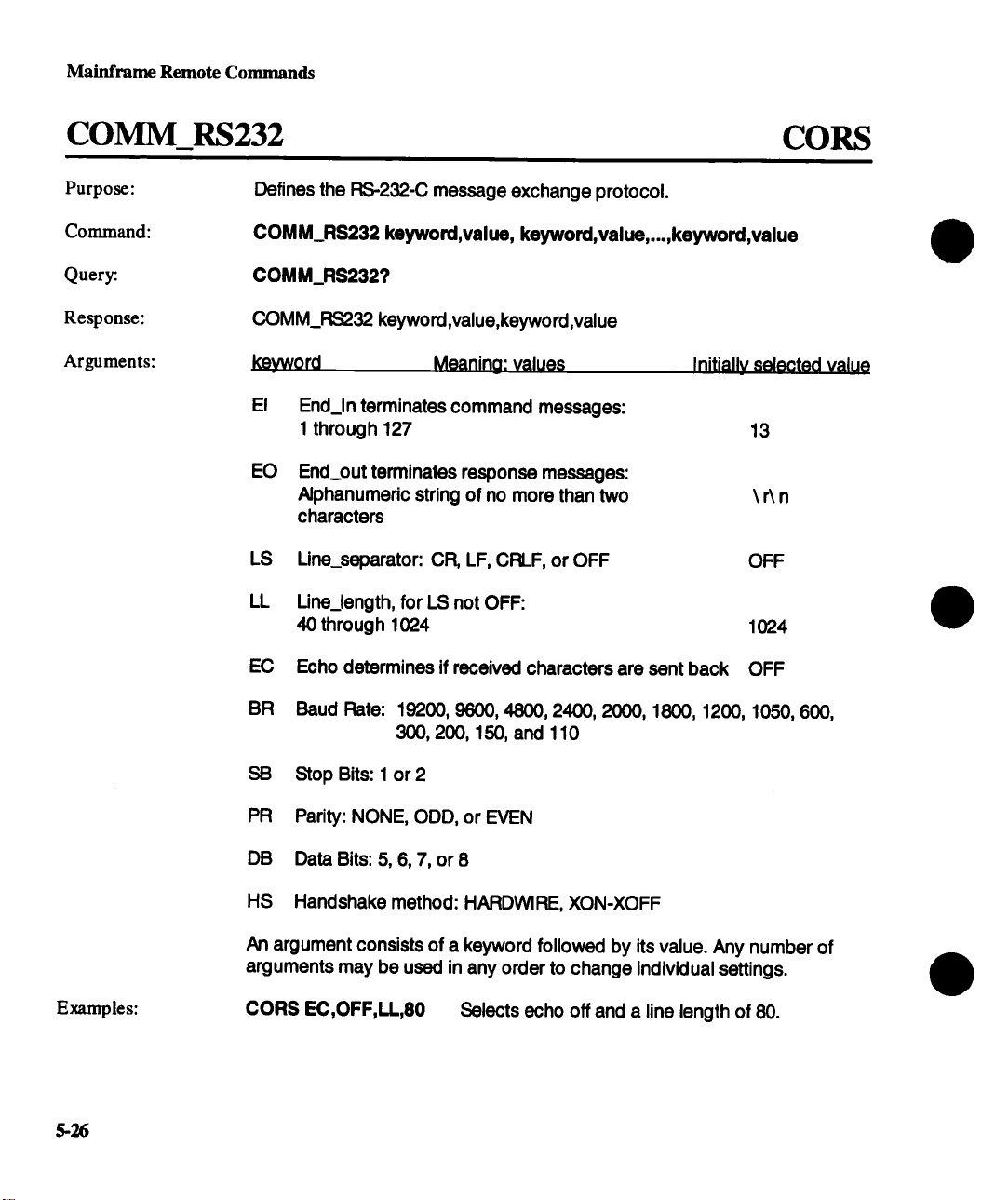
Mainframe Remote Commands
COMM_RS232
Purpose:
Command:
Query:.
Response:
Arguments:
Defines the RS-232-C message exchange protocol.
COMM_RS232 keyword,value, keyword,value,...,keyword,value
COMM_RS2327
COMM_RS232 keyword,value,keyword,value
keyword
El End_In terminates command messages:
EO End_out terminates response messages:
LS Line_separator: CR, LF, CRLF, or OFF
LL Une_length, for LS not OFF:
EC Echo determines if received characters are sent back OFF
Meaning: values
1 through 127
Alphanumeric string of no more than two
characters
40 through 1024
CORS
Initially selected valu0
13
\An
OFF
1024
Examples:
5-26
BR
Baud Rate: 19200, 9600, 4800, 2400, 2000, 1800, 1200, 1050, 600,
300,200, 150, and 110
SB Stop Bits: 1 or 2
PR Parity: NONE, ODD, or EVEN
DB
Data Bits: 5, 6, 7, or 8
HS
Handshake method: HARDWlRE, XON-XOFF
An argument consists of a keyword followed by its value. Any number of
arguments may be used in any order to change individual settings.
CORS EC,OFF,LL,80 Selects echo off and a line length of 80.
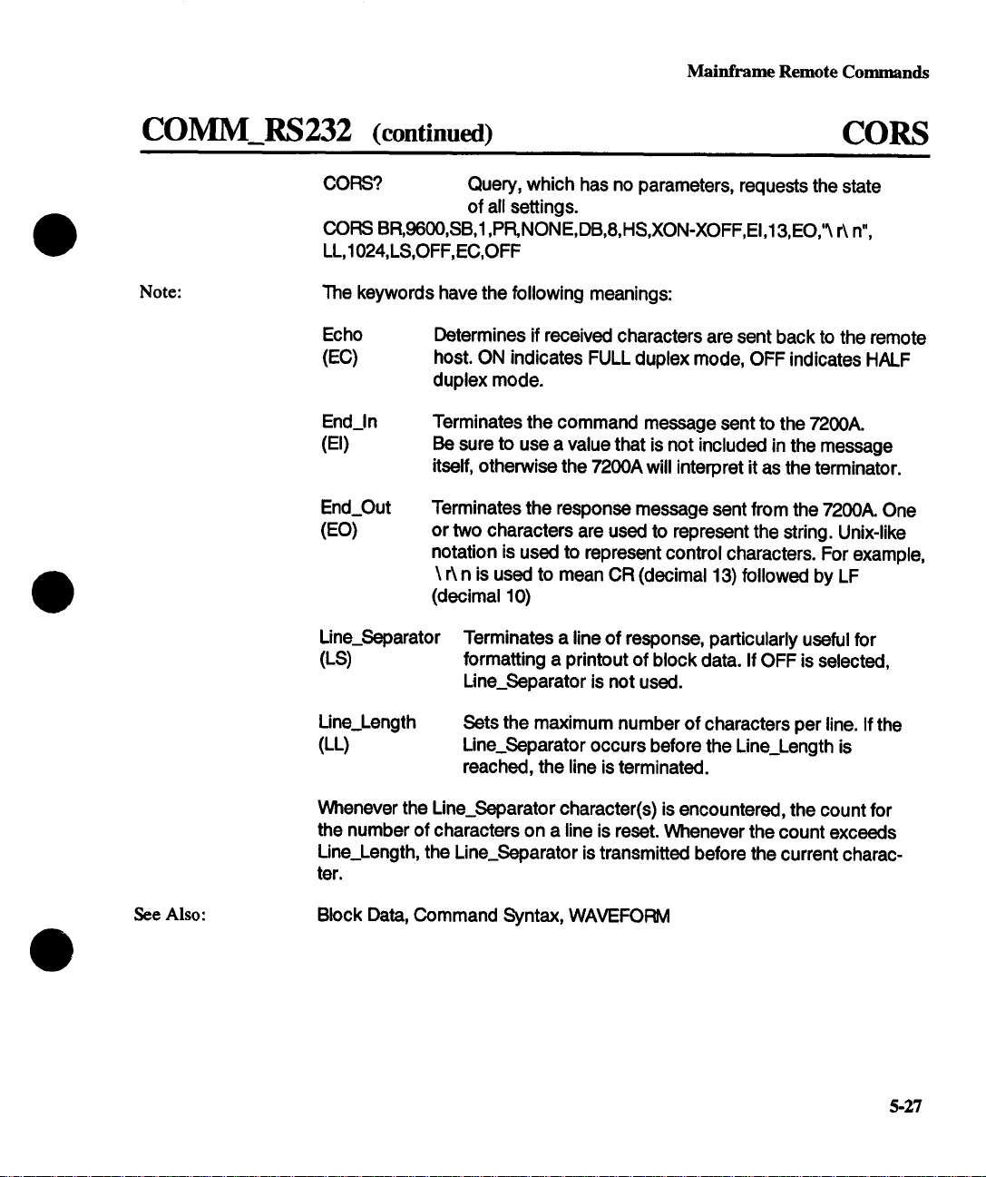
Mainframe Remote Commands
COMM_RS232 (continued)
CORS? Query, which has no parameters, requests the state
CORS BR,9600,SB,1 ,PR, NONE,DB,8,HS,XON-XOFF,EI,13,EO,~ r\ n",
LL,1024,LS,OFF, EC,OFF
Note:
The keywords have the following meanings:
Echo
(EC)
End_in
(El)
End_Out
(EO)
Line_Separator
(LS)
Determines if received characters are sent back to the remote
host. ON indicates FULL duplex mode, OFF indicates HALF
duplex mode.
Terminates the command message sent to the 7200A.
Be sure to use a value that is not included in the message
itself, otherwise the 7200A will interpret it as the terminator.
Terminates the response message sent from the 7200A. One
or two characters are used to represent the string. Unix-like
notation is used to represent control characters. For example,
\ r~ n is used to mean CR (decimal 13) followed by
(decimal 10)
CORS
of all settings.
Terminates a line of response, particularly useful for
formatting a printout of block data. If OFF is selected,
Line_Separator is not used.
See Also:
Line_Length
(EL)
Whenever the Line_Separator character(s) is encountered, the count for
the number of characters on a line is reset. Whenever the count exceeds
Line_Length, the Line_Separator is transmitted before the current charac-
ter.
Block Data, Command Syntax, WAVEFOFWI
Sets the maximum number of characters per line. If the
Line_Separator occurs before the Line_Length is
reached, the line is terminated.
5-27
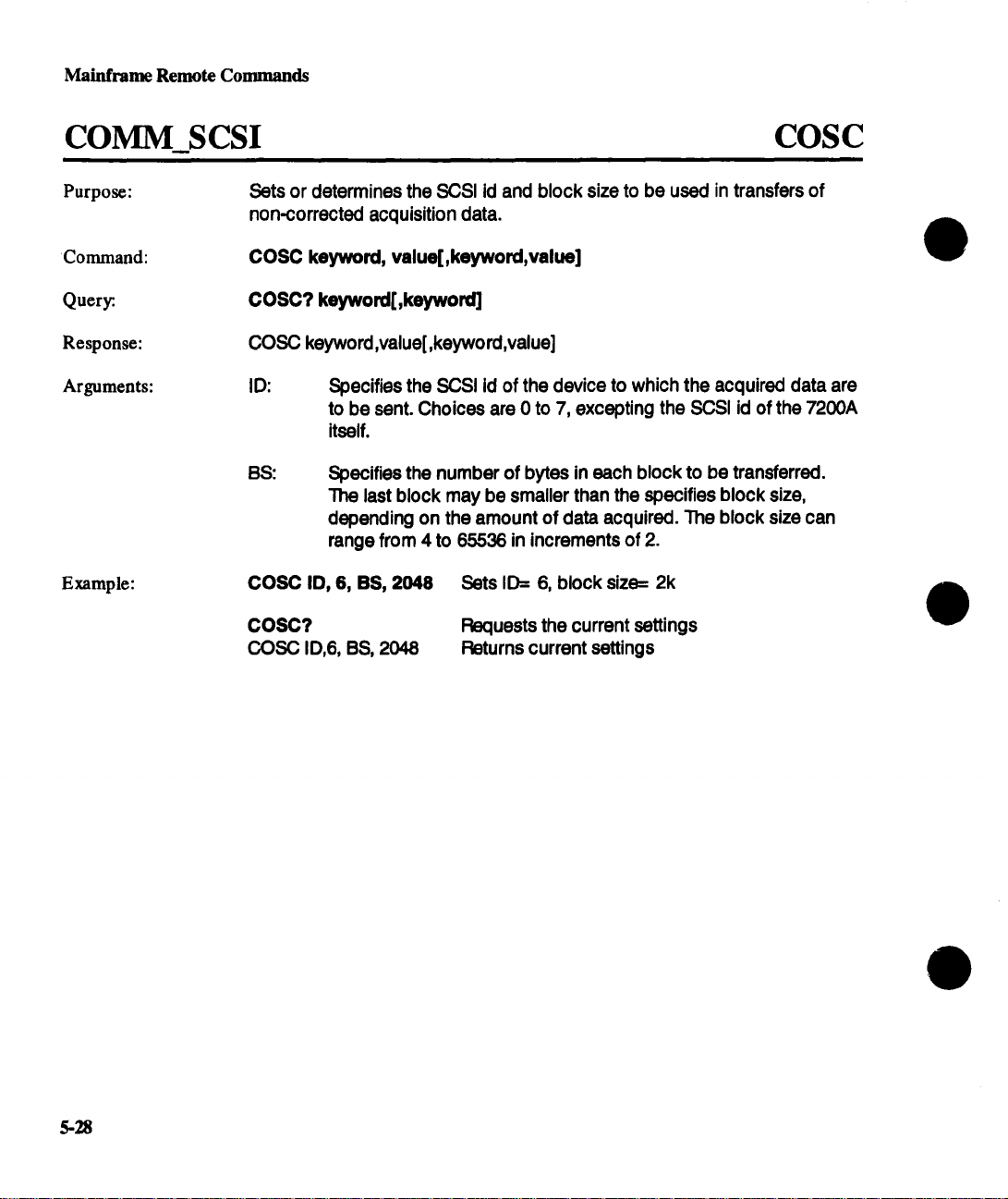
Mainframe Remote Commands
COMM_SCSI
Purpose: Sets or determines the SCSI id and block size to be used in transfers of
non-corrected acquisition data.
Command:
Query:.
Response:
Arguments:
Example:
COSC keyword, value[,keyword,value]
COSC? keyword[,keyword]
COSC keyword,value[,keyword,value]
ID: Specifies the SCSI id of the device to which the acquired data are
to be sent. Choices are 0 to 7, excepting the SCSI id of the 7200A
itself.
BS: Specifies the number of bytes in each block to be transferred.
The last block may be smaller than the specifies block size,
depending on the amount of data acquired. The block size can
range from 4 to 65536 in increments of 2.
COSC ID, 6, BS, 2048 Sets ID= 6, block size= 2k
COSC?
COSC ID,6, BS, 2048
Requests the current settings
Returns current settings
COSC
5-28

Mainframe Remote Commands
COPY_FILE COPY
Purpose:
Command:
Argument:
Copies the specified file(s) from the internal disk to the floppy or vice versa.
COPY_FILE keyword,value
The argument consists of a keyword followed by its value.
Keyword
INPN
INAS
FLPY
Meaning: Value
Panel settings file on the internal disk to be copied
to the floppy disk.
=filename.ext" filename including extension
or =ALL FILES"
Program file on the internal disk to be copied to
the floppy disk.
=filename.ext" filename including extension
or =ALL FILES"
Panel settings or program file on the floppy disk to
be copied to the appropriate directory on the
internal disk.
"filename.ext" fllename including extension
or =ALL FILES"
Examples:
See Also:
COPY FLPY, "MIKE.PNL"
COPY INAS, "ALL FILES"
DIRECTORY_LIST, DELETEFILE
Copy the panel settings file MIKE.PNL
from the floppy to the internal disk.
Copy all program files from the internal
disk to the floppy disk
5-29
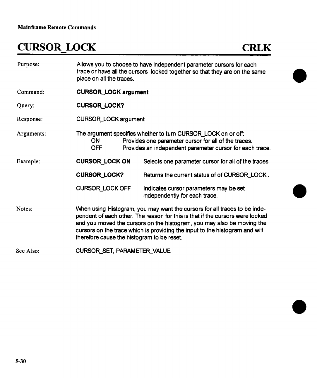
Mainframe Remote Commands
CURSOR LOCK
Purpose:
Command:
Query:
Response: CURSOR_LOCK argument
Arguments:
Example:
Notes:
Allows you to choose to have independent parameter cursors for each
trace or have all the cursors locked together so that they are on the same
place on all the traces.
CURSOR_LOCK argument
CURSOR_LOCK?
The argument specifies whether to turn CURSOR_LOCK on or off:
ON Provides one parameter cursor for all of the traces.
OFF
CURSOR_LOCK ON Selects one parameter cursor for all of the traces.
CURSOR_LOCK? Returns the current status of of CURSOR_LOCK.
CURSOR_LOCK OFF
When using Histogram, you may want the cursors for all traces to be independent of each other. The reason for this is that if the cursors were locked
and you moved the cursors on the histogram, you may also be moving the
cursors on the trace which is providing the input to the histogram and will
therefore cause the histogram to be reset.
Provides an independent parameter cursor for each trace.
CRLK
Indicates cursor parameters may be set
independently for each trace.
See Also: CURSOR_SET, PARAMETER_VALUE
5-30

Mainframe Remote Commands
CURSOR MEASURE CRMS
Purpose:
Command:
Quer~
Response:
Argument:
Displays the specified cursor type if the cursors are not already on.
CURSOR_MEASURE keyword
CURSOR_MEASURE?
CURSOR_MEASURE keyword
kevword
VREL Vertical
Relative
VABS Vertical
Absolute
HABS Marker
HREL Horizontal Measures the difference between the horizontal
PARAM Basic Calculates a fixed set of waveform parameters on
Parameter one trace between two cursors.
Measures the difference between the vertical
positions of two cursors.
Measures the absolute vertical value at a given point.
Measures the absolute horizontal position and its
vertical value of a point on a trace(s).
positions and the corresponding vertical values
of two Horizontal cursors.
meaning
Examples:
Note:
See Also:
EXPAR Extended Calculates up to 20 user selected parameters that
can be defined on any combination of traces.
OFF
CRMS?
CRMS VREL
This command affects the display of cursors, it does not affect the
positioning of cursors (see CURSOR_SET) or their measurement
(see CURSOR_VALUE).
CURSOR_SET, CURSOR_VALUE, PARAMETERVALUE,
XY_CURSOR_SET, XY_CURSOR_VALUE, PER_CURSOR_SET,
PER_CURSOR_VALUE
Display no cursors.
Requests which cursors are currently displayed.
Reports that only the Vertical cursors are being displayed.
5-31

~inframe Remote Commands
CURSOR_SET
Purpose:
Command:
Query:.
Response:
Arguments:
Positions any one of the eight independent cursors at a given screen location when not in XY or persistence mode. Cursor positions are specified
relative to a grid. The positions of the cursors can be modified or queried
even if the required cursor is not currently displayed on the screen.
prefix:CURSOR SET keyword,position,...,keyword,positlon
prefix:CURSOR_SET? keyword,keyword,keyword,...
prefix:CURSOR_SET keyword,position ..... keyword,position
prefix The prefix is limited to traces, i.e., T1, T2 ..... T8.
keyword,position ..... keyword, position
Cursor T.voe
Vertical Absolute VABS -4 to 4 DIV
Vertical Relative VREF, VDIF
Marker
Horizontal HREF, HDIF 0 to 10 DIV
Basic PREF, PDIF 0 to 10 DIV
Extended PREF, PDIF 0 to 10 DIV
Unlocked UREF, UDIF 0 to 10 DIV
keyword position
-4 to 4 DIV
HABS
0 to 10 DIV, or Horizontal units
CRST
5-32
The seven cursor types measure the following:
Verticial Absolute
Vertical Relative
Marker measures the absolute horizontal position and its
Horizontal measures the difference between the horizontal
Basic calculates a fixed set of waveform parameters on one
measures the absolute vertical value at a given point.
measures the difference between vertical positions of
the cursors of a trace(s).
vertical value of a point on a trace(s).
positions and their corresponding vertical values of
two Horizontal cursors
trace between two cursors

Mainframe Remote Commands
CURSOR_SET (continued)
Extended calculates up to 20 user selected waveform parameters that
can be defined on any combination of traces.
Same as basic & Extended cursors but can be positioned
individually on each trace
Examples:
Note:
Unlocked
T1 :CRST HABS, 5 Races the marker in the center of the waveform.
T1 :CRST? HREF
"1"1 :CRST HREF, 2
Keywords ending in REF refer to a reference cursor which is a line of alternating dots and dashes. Keywords ending in DIF correspond to the
difference cursor which contains dashes.
When positioning VREF and VDIF cursors and when the 7200A is display-
ing more than one grid, the specified position is interpreted as the number
of divisions above or below the center of the grid on which the trace is
currently displayed.
A command argument has two parts: keyword followed by position. Any
number of arguments may be used in any order to change individual
settings.
CRST
Requests the position of the horizontal reference
cursor on trace 1
The response indicates the position is two divisions
to the right of the grid’s left edge.
See Also:
If no arguments are specified with the query, all cursor positions are re-
turned.
When querying the position, if the cursor is not on the specified trace, the
value UNDEF is returned.
CURSOR_MEASURE, CURSOR_VALUE, PARAMETER_VALUE,
PER_CURSOR_SET, XY_CURSOR_SET
5-33
 Loading...