

Page 1
9450A
Portable,
Dual-Channel
Digital
Main
I
50K
Automatic PASSIFAIL testing on
templates and parameters
Segmentable memories with trigger
point time stamps
FASTGLITCH trigger mode
Signal processing and
Optional high speed memory card
m
D
Unmatched display quality
TV
Oscilloscope
Features
memory
trigger and
per
XY
channel
display
FFT
analysis
The
Ultimate
for
Design
The LeCroy
bandwidth,
fidelity, extensive trigger capabilities and
signal processing. Aimed at meeting the
demands
working
munications, electronic design and test,
lasers, computers,
defense, the
an indispensable measurement tool in
any laboratory.
Like all LeCroy oscilloscopes, the
9450A
of different instruments: oscilloscope,
transient recorder, counterftimer,
frequency meter, signal averager, data
\ogger
highest performing data acquisition and
processing system available in any
portable
9450A
fast
of
researchers and engineers
in
fields
9450A
is
designed to serve as a range
and
digits\
instrument.
Instrument
and
sampling rates, high
as
vohmeter.
Test
combines high
diverse
NDT,
as
telecom-
physics and
will rapidly become
\t
offers
the
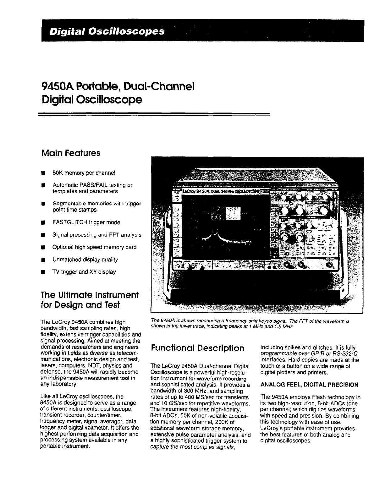
The
9450A
is
shown
shown
in
the
Functional
The LeCray
Oscilloscope is a pawertul high-resolufion instrument for waveform recording
and sophisticated analysis. It provides
bandwidth
rates of
and
The
8-bit ADCS,
tion memory per channel,
addiliona\
extensive pulse parameter analysis, and
a highly sophisticated trigger system
capture the
of
up
10
GS/sec for repetitive waveforms.
instrument features high-fidelity,
waveform storage
measuring
lower
trace,
Description
9450A
Dual-channel Digital
300
MHz,
to
400
MSIsec
50K
of non-volatile acquisi-
most
complex
a
indicating
frequency
peaks
and sampling
for transients
200K
of
memory,
signals,
at
to
shitf
keyed
1
MHz
signal. The
and
1.5
including spikes and glitches. It
oroarammable
;nt&aces. Hard copies
touch
of
digital ploners and printers.
ANALOG
a
9450A
The
its two high-resolution, 8-bit
per channel) which digtize waveforms
with speed and precision. By combining
this technology with ease of use,
LeCroy's
the best leatures of both analog and
digital oscilloscopes.
FFT
of
the
MHz.
over
a button
on
FEEL, DIGITAL
employs Flash technology in
portabie
waveform
GPlB
or
are
a wide range of
PRECISION
instrument
is
is
fully
RS-232-C
made
at the
ADCs
(one
provides
Page 2
The front-panel controls of the 9450A
have been laid out in the style of an
analog oscilloscope, making it easy to
use from the very first moment. The
analog feel is enhanced by the rapid
instrument response and the fact that
waveforms are presented instantly on
a
bright high-resolution screen. For
automated test applications at1 the
front-panel controls, including cursor
positions and internal functions, are fully
programmable over RS-232-C or
interfaces.
Capturing and measuring signals has
never been easier. For repetitive signals
an auto-setup facility finds and displays
signals in less than
time phenomena the 9450A's long 50K
memories and extensive triggering
capabilities enable signals to be captured the very
signal speed and duration are uncertain.
LONG NOH-VOLATILE MEMORIES
Only long memories allow high-fidelity
recording over extended periods of time.
On equal time-base settings the 9450A,
with 50K of memory per channel, will
sample waveforms up to 50 times faster
than an oscilloscope with only
memory. Faster sampling means better
single-shot bandwidth, better time
resolution and the power to expand
waveforms up to 1000 times to see
details that completely elude other
digital oscilloscopes. In addition, when
segmented, the
acquisition memories can store up to
200 waveforrns/channel (complete with
date and time stamps).
2
seconds. For one-
first
time, even when
9450A's
non-volatile
1
K
GPlB
of
TRIGGER
Push-button control enables the user to
choose the appropriate trigger functions
for his signal: standard triggering for
basic measurements and advanced
triggering to meet highly sophisticated
requirements.
The standard trigger facility provides all
the conventional trigger functions. Front-
panel controls select and adjust param-
eters such as pre- and post-trigger
settings, trigger level, slope, mode and
coupling. To help users quickly deter-
mine the
conditions,
of illustrative trigger graphics.
SMART triggering offers a solution to
even the most intricate triggering
problems. For example, FASTGLITCH
trigger can be used to locate and reveal
glitches and spikes less than 2.5 nsec
wide. Time-qualified trigger
ranging applications and can be used to
ignore unwanted signal
trigger features include hold-off (by time
or number of events), gated triggering
and conditional triggering, qualified
trigger, and trigger delayed
number of events.
The PASSiFAlL routine enables the
oscilloscope to compare a source
against a tolerance mask while simultaneously testing
parameters.
9450A's trigger mode and
LeCroy has created a series
is
ideal for
ref[ections. Other
by
time or
a
set of extracted
trace
For instance, the oscilloscope can be set
PASS
up to
1,
The waveform in Channel 1 is
contained in
(all points inside the mask).
2.
The frequency in Channel 2 is less
than 10
3.
The maximum value of Function
is more than 1.45
4.
The
less than 850
If
any of these four conditions is not
satisfied, the test will FAIL.
Whether the test PASSes or FAILS, the
oscilloscope can, if the user wishes,
perform any or all of the following
actions:
-
Stop the acquisition.
-
Make a screen dump.
-
Store a trace to Memory
-
Store the selected traces to the
memory card.
-
-
Send a pulse from the rear-panel
accessory port.
The mask envelope can also be gener-
ated inside the oscilloscope.
if:
the
kHz.
RMS
value in Channel 1 is
Emit a "beep".
mask in Memory
V.
mV.
D.
C
F
Page 3

9450A
Specifications
\/ERTICAL
Bandwidth
@
50
@
1
probe t~p
Input impedance: 1 MQ1l 5
50
Cl11%
Channels: Two Independent channels;
standard
Sensitivity range: 5 mV:dtv
continuously var ab e from 1 to 2 5
the
5
mV1d1v to 2 Vldlv (In a
Vertical expansion: Up to 5 tlrnes (wlth
averaging
sensltrvlty).
Scale factors: Probe attenuation factors of
XI
selected
Offset:
In
0 02
j;24
DC
Bandwidth
Max~mum input voltage:
AC
5V
ANALGC;
(-3
ii,
DC
to
Mi.!
DC
DC
BNC
flxed setlrng F~xed settlngs
up to
Xlo,
X100, XlG00 X10G00
and
are remotely programmable
i12
times the flxed ssnsitivity setting
drv~s~on increments up to
dlv @ 10
accuracy:
Ilmlter:
10
kHz)
RMSat50R
SECTION
dB):
300
MHz
to
250
MHz
connector lnputs
I
2,
50
l~mes or
mV~div,
248
drv
<i2%,
fuli scale
80
MHz
NlQ
250
55 V DC
a?
1
pF and
to
100
(-3
typical
at
2
Vidiv,
trmes
range
5
sequence)
rnV/dlv
may be
5'0
@
5
mVidiv
dB)
typlcal
V
(DC
(500
the
frow
V rnax
+
peak
mW) or
VERTICAL DIGITAL SECTION
ADCs:
One per channel, &bit Flash.
400
+I
0
(battery
50
E
and
MSIsec for
repetitive
psec.
backed for
kllowords per
D:
F:
Two
Conversion rate: Up to
transients,
slgnals, s~multaneously on both channels.
Aperture
Acquisition memories, Channel 1 and
Non-volallle memories
a
rnlnlmum
channel can be segmented into
50. 100
Reference
word
andlor processed waveform, or up to
waveforms when segmented.
Function memories
bjt word memo-ies for waveform processing.
PEAK
Minimum and maximum peaks, as fast as
;
0.002%
2.5
1
00%
FASTGLITCH trigger technique
trigger section below), glitches faster than
2.5
settings.
up
to
10
GS/sec for
uncenalnty:
of
2
years) of
or
200
segments.
memories, C and
rnernorles whlch can store one acquired
AND
GLITCH DETECTION
of the record length (minimum
nsec), are captured and displayed with
probabili:y. Using LeCroy's new
rlsec can be detected on ali time base
2,
50K.
(see
5,
50K,
2:
10, 20,
16-bit
205
16-
the
HORIZONTAL SECTION
Time Base
1
Range:
Clock accuracy: 5 -10.002"/0.
lnterpolator resolution: 5 psec.
Interpolator accuracy:
Sampling clock output:
rear panel.
External clock in:
panel.
Acquls~t~on Modes
Rendom Interleaved Sampling (RIS):
For repetltlve
to 5 psecidlv.
S~ngle shot: For translent s~gnals and
repetitive
200
Roll: For s owly changlng s~gnals from
500
Sequence mode: D~vldes the acqulsll~on
memory inlo
segments.
Horizontal expansion: Dual Zoom mode
allows two different
sectlons
up to
nsecldiv to
slgnals from
msecld~v
rnsecidiv to
2, 5
of
the same s~gnal to be expanded
I
,000
times.
5000
BNC
signals
from 1 nsectd~v
5000
10,
signals
secidiv.
20
psec
RMS.
BNC
connector on
connector on rear
10
nsectdlv to
sec!d~v
20,
50, 100
or
or two
different
200
The
94504
t~me
(1
sequence
00
psec) bemeen
mode
collects several segments with very little
segments.
Na~n
New
Duo)
Zam
mode
The
display
placement
0.002%
timebase accuracv.
T
At
3
I&
262.78797
BU5369ps
cx7
kHz l/div
of acquired waveform and
of
measurement
cursors
c
v
expanded
and full
9r~
v
nc
views
use
of the oscilloscope3
X
Chm
I
*,
Crxn
l
-3%
mi,
--
Ctil
.?
v
lOnV
?
WE
I!
.
precise
CH2
allows
Page 4

TRIGGERING
Pretrigger recording: Adjustable in
increments to 100% of full scale (grid width).
Post-trigger delay: Adjustable in
increments
External trigger Input:
max.
External trigger range:
EXnl
Rate: Up to 500
coupling.
Timing: Trigger timing (date and time) is
logged in the memory status menu. The liming
of subsequent triggers in sequence mode is
measured with 0.1 sec absolute resolution, or
nanosecond resolution relative to the time of
the first trigger.
Trigger output: BNC connector on rear panel.
Trigger veto:
Standard Trigger
SMART
up
to
10,000 divrsions.
1
(DC
+
peak
0.
MHz
BNC
Sources: CHANI
EXT/IO.
independent trigger circuits allowing slope,
coupling and level to be set individually for
each source.
Slope: Positive, negative.
Coupling:
Modes:
Single-source trigger operational
modes:
CHANI,
HF.
Auto:
Automatically re-arms after each
sweep. If no trigger occurs, one is
generated at an appropriate rate.
Normal: Re-arms after each sweep.
no trigger occurs after a reasonable
length of time, [he warning message
or
SLOW
TRIGGER"
Single
(hold): Holds display after a
trigger occurs. Re-arms only when the
button
"single"
Sequence: Stores multiple events
segmented acquisition memories.
Trigger
Hotd-off
Hold-off
by
by
Ma,
AC
5:
10
kHz).
k2
V
using
Hf
connector on rear panel.
,
CHAN2,
CHAN2
AC,
LF
REJ,
is displayed.
is pressed again.
tlrne:
25
nsec to
events: 0 to
0.2%
0.02 division
<
20
pF,
250
in
EXT,
120
trigger
LINE.
HF
EXT,
REJ.
DC.
If
"NO
and EXT have
in
20
sec.
10g
events.
V
V
in
Width-based trigger
Pulse
width < (FASTGLITCH): Triggers
on opposite slopes of pulses narrower
than a value in the range
20
sec.
Pulse width
slopes of pulses wider than a value in
range
the
Interval width
slopes of signals narrower than a value
in the range
Interval
slopes of signals wider than a value in
the range
Multi-source trigger operational modes:
Pattern: Triggers on the logic
the three sources
EXT, where each source can be defined
as
trigger can be selected at the beginning
(entered) or the end (exited) of the
specified pattern.
Bi-level: This is a special condition
pattern trigger which allows the
to trigger on
certain preset high or low trigger level.
The signal must be connected
simultaneously to two channels. The
third trigger channel
care
State quallfled: Allows the
trigger on any source
or EXT), while requiring that a certain
pattern of the other two channels is
present or absent. A delay by time or by
number
the moment the pattern is valid.
Timeievent qualified: Allows the
to
CHAN2
pattern of the three channels is entered
or exited. From the moment of validity,
a delay can be defined in terms of time
or number of events.
TV:
signals that comply with
NTSC standards. Selection of both line
(up to
possible. Active on EXT only.
2.5
width
25
high
(H),
(X).
of
events can be selected from
trigger on any source
or
EXT),
Allows stable triggering on
1500)
modes:
2.5
nsec and
r:
Triggers on opposite
nsec to
20
sec.
z:
Triggers
10 nsec to
r:
Triggers on similar
nsec to
20
20
sec.
on
sec.
similar
AND
low
any
CHANI,
(L)
signal
or
must
don't
that
CHAN2
care
exceeds
be set
9450A
(CHAN1,
(CHAN1,
as
soon
as
a certain
TV
PAL, SECAM
and field number (up
of
and
(X).
The
of
9450A
a
to
don't
to
CHAN2
9450A
to
8)
or
is
DISPLAY
CRT:
12.5
x
17.5
cm
(5
x
7
deflection; vector type.
Resolution:
Real-time clock: Date, hours, minutes,
Grid: lnternaliy generated; separate intensity
control for grid and waveforms. Single, dual
and pulse prameter measurement grid
mode.
Persistence mode: Plots consecutively
acquired traces of up
(CHANl, CHAN2. Memory C or
or F and Expansion A or
other, allowing waveform irends and history to
be examined. The number of sweeps is
selectable from
INFINITE. Time and voltage cursor
measurements are supported in persistence
mode.
XY
mode: Plots any
and
2,
D
ard Functions E and
another. Operates on live waveforms with fuil
cursor readout.
Hard
as well as printers can be used to make hard
copies of the display. Screen dumps are
activated by
remote
7400
Graphtek
Pr~nters supported are: EPSON and the HP
ThinkJet, QuietJet and LaserJet. Plotting can
be done in parallel with normal
operation.
Graphics: Waveforms and display
information are presented using vector (linear)
graphics. Expanded waveforms use LeGroy's
DOT-LINEAR graphics that highlight actual
data points and interpolate linearly between
them.
Menus: Waveform storage; acquisition
parameters; memory status;
panel configurations;
waveform parameters,
configuration; hardcopy setup and real-time
clock setup, averaging, arithmetic, and
FAIL.
4096
x
1,
2,
Expansions A and
copy:
Single
a
front-panel push-button or via
control.
FP
Plotters
5301,
and 7500 series, Philips
inches); magnetic
4096
points.
to
four sources
D.
8)
5
10.
two
sources (CHAN1
8,
F)
against one
or
multi-pen digital p\otte!s
supported are the
and cornpatib\e
SMART
RS-232-C
Function
on top of each
20,
50,
100, 200 or
Memories C and
PM
81
51,
models.
9450A
savelrecall front-
trigger;
see.
E
HP
PASS1
Page 5

Cursors
Relative
time:
Two
measurements with a resolution of
full scale for unexpanded traces: up 10
the sampling interval for expanded traces. The
corresponding frequency
provided.
Relative voltage: Two horizontal bars
measure voltage
scale for each trace.
Absolute time:
measures absolute voltage versus signal
ground, as well
trigger.
Absolute voltage: A reference
absolute voltage with respect to ground.
Pulse
parameters: Two cross-hair cursors
are used to define a region of interest for
which pulse parameters will be calculated
automatically.
AUTO-SETUP
Pressing the auto-setup button automatically
scales the time
settings
to
range
Type of signals detected: Repetitive
with amplitudes between
frequency above
greater than
Auto-setup time: Approximately 2 sec.
provide a stable display for a wide
of
repetitive input signals.
W4VEFORM
Waveform processing routines are set up via
menus.
These inclt~de arithmetic lunctions
(add, subtract and invert), and summation
averaging
Pulse parameters: Based on ANSlilEEE Std.
181-1977
and Analysis
lerminology
1977
(up
"Standard on Pulse Measurement
"Standard Pulse Terms and Definitions".
cursors provide time
information
diflerences
A
cross-hair marker
as
the time relative to the
Dase, trigger and sensitivity
50
0.1%.
PROCESSING
to
1800
by
Objective Techniques".
is
derived
2
Hz
and a duty
signals).
from
to
50.2%
bar
mV
and
IEEE Std.
k0.0546
10%
is also
of full
measures
sigrals
8
V,
cycle
The
194-
of
of
Automatic measurements determine:
Arnptitude Frequency Period
Area Maximum Pulse Width
Base Mean Rise Time
Cycles
Delay Overshoot
Duty Cycle Overshool Pos Top
Fall Time Peak-Peak
Sources:
Function E or
define the
1
pulse
averaged results for period.
and
fall
REMOTE CONTROL
Front-panel controls, including variable gain,
offset, position controls and cursors,
as
all internal func!ions
RS-2324 port: For cornputer/terminal control
or plotter connection. Asynchronous up lo
19200
GPlB port:
listener tor computer control
liansfer.
Minimum
CHANT,
CHAN2.
F,
Expansion
rneasu:ement zone. W~th more than
present in the measurement zone,
time
ate presented.
RMS
Neg
Standard
Memory C or
A
or
B.
widih,
Cursors
rise time
as
are
programmable.
baud.
(IEEE-488).
Configured
and
fast
as
data
Dev
D,
well
taikerl
PROBES
Model: Two
Probe
1
v
Probe power: Two rear-panel power outlets
for use wlth actlve probes provide
+5 v DC.
SELF
Auto-calibration ensures specified DC and
time accuracy.
P9020
calibration: 1 kHz square wave,
v-P
probes supplied.
TESTS
r15
V.
GENERAL
Temperature: 5 to
0
to
50°
C
Humidity:
Power required: i tO
440
Hz,
275
Shock and vibration: Meets requirements
MIL-STD-81OC
specifications,
Battery backup: Lithium batteries rnainta~n
front-panel settings and waveform data
years.
Dimensions:
18.5
x
14.5 x 20
Weight:
shipping.
Warranty: 2 years.
15
ORDERlNCi
Oscilloscope
Code Description
9450A
9450AWPOt
9450AWP02
945OAMATE CllUMATE optlon
9450A-MC01
9450A-MC02 128K
9450A-MC04
OM945OA
94XX-FC
40"
C
(41
(32
<
to
80%.
122"
F)
operating.
or
220
V
to
AC,
W.
modified to LeCroy design
and
MIL-T-288OOC.
(HWD)
21 x 37
kg
inches).
(33
lbs) net.
20
x
kg
1NFORMATlON
and
Options
31g1tal osc~lloscope
Waveform processing option
FFT
processmg
Memory card reader
memory card
51
2K
memory ~ard
Operator's manual
Front cover
104"
50
(44
option
45
cm,
F)
to
Ib)
rated;
for
2
of
 Loading...